AUSTRALIAN JOURNAL OF BASIC AND
APPLIED SCIENCES
ISSN:1991-8178 EISSN: 2309-8414 Journal home page: www.ajbasweb.com
Open Access Journal
Published BY AENSI Publication
© 2016 AENSI Publisher All rights reserved
This work is licensed under the Creative Commons Attribution International License (CC BY).
http://creativecommons.org/licenses/by/4.0/
To Cite This Article: A.Kanagalakshmi, A.Mahadevan and A. Veeralakshmi., Design of Low Cost Microstrip Antennas for Wireless Sensor Networks. Aust. J. Basic & Appl. Sci., 10(1): 417-424, 2016
Design of Low Cost Microstrip Antennas for Wireless Sensor Networks
1A.Kanagalakshmi, 2A.Mahadevan and 3A. Veeralakshmi
1,2,3Asst. Prof., Department of ECE, Sree Sastha Institute of Engineering and Technology, Chennai, India.
Address For Correspondence:
A.Kanagalakshmi, Asst. Prof., Department of ECE, Sree Sastha Institute of Engineering and Technology, Chennai, India.
A R T I C L E I N F O A B S T R A C T
Article history:
Received 10 December 2015 Accepted 28 January 2016 Available online 10 February 2016
Keywords:
Sensor mote, microstrip antennas, link budget calculations
In recent years, new technologies have shaped numerous military and commercial strategies in an unprecedented way. The Wireless Sensor Network (WSN) technology is one such technology and has been attracting significant attention. WSN provide a promising infrastructure for gathering information about parameters of the physical world which can be subsequently processed for both commercial and military applications. Miniaturization of sensor mote is a major factor in which antenna size reduction is difficult. Our objective is to address that issue. Here two miniaturized 2.4GHz dipole and monopole antennas (3mm x 40mm, 16mm x 28mm) are proposed for different applications. Usually unbalanced antennas are used in sensor motes. Implementing a balanced antenna in small node is problematic in both design and characterization. Thus planar antennas are proposed for such applications. Also link budget calculations are made and results are discussed.
INTRODUCTION
The increasing miniaturization of RF devices coupled with advancements in wireless networking have enabled a new generation of massive-scale sensor networks suitable for many applications. These have inspired numerous research investigations in the area of wireless sensor networks (WSN) (Akyildiz, F., et al., 2002). In the new generation of large-scale sensor networks, sensors will normally be employed in miniature autonomous devices known as sensor nodes to form the network without the aid of any established infrastructure (ad-hoc topologies). The individual nodes are capable of sensing their environments, processing the information locally, and sending it to one or more collection points through a wireless link. Each node normally has low RF transmit power which helps in prolonging the lifetime of the battery. This is necessary because the sensor nodes in many applications are mostly inaccessible, thus requiring the sensors to operate without battery replacement for a long time (Akyildiz, F., et al., 2002). Such conditions make the RF channel and power consumption characteristics a critical factor in the sensor network system design and deployment. It is important to have a good understanding of these characteristics as such factors ultimately affect the WSN operating characteristics (such as available range, battery lifetime, antenna design, etc.), cost and deployment feasibility. WSN can be used for many military and commercial applications, and in many of these applications the size of nodes, RF behaviours and energy consumption rate are the key factors in designing WSN (Sleman and R. Moeller, 2008; Hac, A., 2003; Malan, D., et al., 2004). Also the technical overviews of the Crossbow IRIS wireless network sensors will be discussed.
1.1 Characteristics of wireless sensor mote:
secondary nodes. Wireless sensor networks are typically highly distributed and they are typically self organizing, low power and lightweight in design resulting in a wide diversity of uses
(
Sleman and R. Moeller, 2008;
Hac, A., 2003;
Malan, D.,et al., 2004)
.The network sensor’s ability to self-organize is necessary to synchronize network operations among the sensor nodes themselves and between sensor nodes and base stations. It allows for unattended wireless sensor network operation and it is incorporated mostly in software. In both military and commercial network applications, users place high regard on the network sensor’s ability to adapt to the dynamic network environment and it is this self organizing capability that determines the reliability and scalability of any wireless network sensor
(
Sleman and R. Moeller, 2008;
Hac, A., 2003;
Malan, D.,et al., 2004)
.Low power operation of the sensor network is another characteristic that has vast implications on the performance of a network sensor. Network sensors are often required to be deployed in an environment where access to the network sensors is nearly impossible and the battery replacement for such network sensors is impractical. In such a situation, low power operation is necessary to reduce any chance of mission failure as a result of insufficient battery life. The battery life requirement is normally application specific, and typically two to four years is desirable. There are typically two ways to control the battery life. The less direct way is by finding a means to optimize the network sensor operation such that the power requirement is minimized. One good example would be the sleep mode operation: the sensor turns itself off when nothing is sensed. A more direct way is the improvement of battery technologies. This has aroused a vast level of interest in many research industries, but not much more advancement has been seen in the area of wireless sensor networks. This is limited by the fact that the size of the battery is a governing factor in producing a small sized network sensor device
(
Sleman and R. Moeller, 2008;
Hac, A., 2003;
Malan, D.,et al., 2004)
.A network sensor is typically design diversified and is normally scalable and capable of supporting a vast level of applications. Such a sensor is capable of providing the essential support in medical, military and commercial applications such as emergency care, disaster response, vital sign sensor detection, battlefield awareness, localization, building monitoring, security monitoring, environmental monitoring, etc. There is a huge range of applications and it is desirable to have network sensors that are designed to accommodate this diversity. CROSSBOW IRIS is a good example that is commonly utilized in medical and military and commercial applications (www.xbow.com). The well-known performance limitation for electrically small antennas (Wong, K.-L., et al., 2003; CHU, L.J., 2005; Harrington, R.F., 1960) is a problem, because of the contradictory system requirements of both small size and high efficiency. As the antenna is affected by the environment, designing a robust antenna in the proximity of the body is really challenging. This makes it even more important to examine every alternative antenna design. As a differential transceiver is chosen for the sensor node, a balanced antenna without an external balun or matching network is preferred in order to lower the cost. Moreover, such an antenna might be less sensitive to the surroundings, compared with an unbalanced antenna.
1.2 Crossbow iris mote:
Crossbow Technology, Inc. (www.xbow.com) a leading supplier of wireless sensor technology and inertial MEMS sensors for navigation and control, announced today the release of IRIS™, a new family of ultra low-power, long-range wireless sensor network products. The IRIS platform features the following:
• Wider coverage area, with up to three times the radio range of comparable devices using IEEE 802.15.4 compliant radios
• Ultra low-power consumption with half the sleep current of previous products for longer battery life • Optimized for richer applications with twice the program memory of previous products.
The IRIS OEM Module is a 24mm x 24mm “postage stamp” module optimized for fast, seamless integration of low power, wireless mesh-networking into OEM hardware designs. Once customers complete their evaluation, they transition from engineering prototype to volume production using this surface-mount, stamp-size module.
Link budget calculation:
A simple link budget equation is given by
Received Power (dBm) = Transmitted Power (dBm) + Gains (dB) − Losses (dB).
With RF power of 3 dBm (typ), receiver sensitivity of -101 dBm (typ), cable loss of 0.9dB and also the gain of the antennas as 2dBi, using link budget calculator the distance communicated by the antenna will be 400m and also the received signal strength will be -86dBm. Similarly, with same RF power and sensitivity and the gain of the antennas as 0.5dBi, the distance communicated by the antenna will be 150m and also the received signal strength will be -86dBm.
The CROSSBOW IRIS mote uses quarter wave dipole antenna of whip type is not suitable for applications in which motes are thrown for measurement. Hence we go for planar printed type of antennas where antennas are printed on Printed Circuit Boards (PCB) of the mote itself.
Microstrip antennas are frequently used in today's wireless communication systems because of their low profile, light weight and low production cost which widely have been researched and developed in the recent twenty years (Sleman and R. Moeller, 2008; Hac, A., 2003; Malan, D., et al., Wong, K.-L., et al., 2003). Nevertheless, there are several disadvantages of microstrip antennas. Narrow operation bandwidth is the main disadvantage. The bandwidth of the basic patch antenna is usually 1 – 3%. The bandwidth of the antenna depends on the patch shape, dielectric constant, the thickness of the substrate and the resonant frequency (CHU, L.J., 2005).
Planar Monopole Antenna:
The monopole antenna shown in Fig. 1 is fed by a 2-mm-wide microstrip transmission line. The antenna provides ISM band (2400–2484 MHz) operation with resonance at 2450 MHz. The longer strip is responsible for this band when connected to the feed point.
The PCB is a 1.0-mm-thick FR4 substrate whose dielectric constant and loss tangent are 4.4 and 0.02, respectively with transverse dimensions of 16mm x 28mm. A time-domain Gaussian derivative pulse was used as the source of excitation. The Gaussian pulse was applied at the input of the microstrip transmission line through a 50Ω series source resistor. Energy in the computational space can be dissipated faster through the
source resistor, and fewer time steps are required for the transient analysis. This is especially true in the analysis of a highly resonant structure such as a microstrip patch antenna.
Fig. 1: Miniaturized microstrip-fed planar antenna on a 16 x 28 (mm) FR4 substrate. All dimensions are in
millimetres.
RESULTS AND DISCUSSION
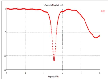
By using CST simulator the given antenna is designed and the antenna is well matched to 2.4 GHz, since the return loss is very less than -10dB is obtained as shown in Fig.2.
The far-field radiation pattern is calculated when the antenna is driven by a sinusoidal source voltage. Transient input voltage and current are recorded during the simulation. When the fields achieve steady-state within the FDTD computational space, a discrete Fourier transform is performed over a virtual surface which encloses the radiating structure to calculate the far zone fields of the antenna. Once the input power and the far fields are known, efficiency and gain pattern at various planes can be computed.
CST MICROWAVE STUDIO is a full-featured software package for electromagnetic analysis and design in the high frequency range. It simplifies the process of inputting the structure by providing a powerful solid 3D modelling front end. After the component has been modelled, a fully automatic meshing procedure is applied before a simulation engine is started. CST MICROWAVE STUDIO is part of the CST DESIGN STUDIO suite and offers a number of different solvers for different types of application. Since no method works equally well in all application domains, the software contain four different simulation techniques via the transient solver, frequency domain solver, integral equation solver and eigen mode solver, to fit best to their particular applications. The most flexible tool is the transient solver, which can obtain the entire broadband frequency behaviour of the simulated device from only one calculation run (in contrast to the frequency step approach of many other simulators).
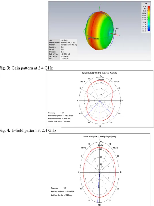
E-field, H-field, and gain pattern of the miniaturized monopole antenna at 2.4 GHz is calculated as shown below
Fig. 3: Gain pattern at 2.4 GHz
Fig. 4: E-field pattern at 2.4 GHz
3.1.2 Measured results and discussion:
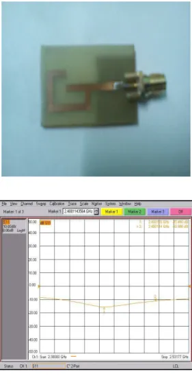
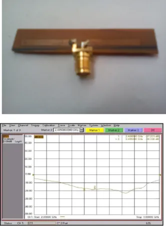
The simulated antenna is fabricated in FR4 substrate of permittivity 4.6 and loss tangent of 0.025 and results are measured in the network analyser present in the TIFAC CORE in Thiagarajar College of engineering.
Fig. 6: fabricated antenna
Fig. 7: Measured return loss
Gain obtained from the proposed monopole antenna is positive and less than 1dBi.Hence this antenna is suitable for short range commercial applications.
Printed dipole antenna:
The approach proposed in this paper is to design microstrip dipole resonance at 2.4 GHz frequency band. Figure 1 shows the structure of a microstrip dipole of length L, width W and gap G that were used in simulation. The proposed antenna element is printed on a FR4 substrate with a dielectric constant of 4.7, a thickness of 1.6 mm and a conductor loss of 0.019. The two hatched rectangular pieces in Figure 1 are copper on the top of the substrate. Each of it is connected with the microstrip bend. The gap between the two pieces is G and the microstrip dipole is fed at the middle of the gap. One piece of the hatched is fed with connector and another one is connected to the ground.
3.2.1 Simulated results and discussion:
The length of each hatched rectangular is about quarter-wavelength. In this case the length of rectangular hatched, L1=L2= λ/4=17 mm and the gap between the two pieces, G = 0.9mm. At the designed frequency,
approximation of the width W is made and it is equal to 2.90 mm. Overall, the length of the dipole is about, L = 40mm. In addition the microstrip bend is added between the two rectangular hatched which has length and width is equal to 2.9 mm.
The design procedure of microstrip dipole antenna design can be carried out in a few steps as follows:
• The resonance frequency is chosen and for this case resonance frequency at 2.4GHz is chosen.
• Calculate the correct dipole dimension (L1, L2 and W) by using microstrip transmission line formula.
• Connect the rectangular hatched with microstrip bend and chooses the suitable gap G between the two
hatched pieces on the substrate.
• The gap between the two traces is G and the microstrip dipole is fed at the middle of the gap.
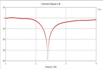
By using CST simulator the given antenna is designed and the antenna is well matched to 2.4 GHz, since the return loss is very less than -10dB is obtained as shown in Fig.5
Fig. 9: Return loss of printed dipole antenna obtained from CST simulator
The far-field radiation pattern is calculated when the antenna is driven by a sinusoidal source voltage. Transient input voltage and current are recorded during the simulation. When the fields achieve steady-state within the FDTD computational space, a discrete Fourier transform is performed over a virtual surface which encloses the radiating structure to calculate the far zone fields of the antenna. Once the input power and the far fields are known, efficiency and gain pattern at various planes can be computed.
E-field, H-field, and gain pattern of the miniaturized dipole antenna at 2.4 GHz is calculated as shown below.
Fig. 11: E-field pattern at 2.4 GHz
Fig. 12: H-field pattern at 2.4 GHz
3.1.2 Measured results and discussion:
The simulated antenna is fabricated in FR4 substrate of permittivity 4.6 and loss tangent of 0.025 and results are measured in the network analyzer present in the TIFAC CORE in Thiagarajar College of engineering.
Fig. 13: fabricated antenna
Gain around 2dBi states that dipole is suitable for long range military applications.
Conclusion:
A miniaturized, low-cost, and easy to manufacture monopole antenna is presented. The monopole antenna achieves excellent ISM band operation and can be built on the edge of a PCB of a sensor mote, or any other wireless equipment. The ground metallization underneath the radiator must be cleared for proper operation. The gain of the antenna has to be improved for long range applications. A low cost microstrip dipole antenna for sensor mote operations in the 2.4GHz band has been proposed. By having its dipole near one half wavelengths, the antenna radiates bidirectional in the E-plane. The dipole was prototyped and tested. Measurement and simulation result was compared. The bandwidth for microstrip dipole is 14.68% greater than monopole antenna. With the increased gain, it is suitable for long range military applications
REFERENCES
Akyildiz, F., W. Su, Y. Sankarasubramaniam and E. Cayirci, 2002. “A survey on sensor networks,” IEEE Commun. Mag., 40(8): 102-114.
Bahadır, S. Yıldırım, 2006. “Low-Profile and Planar Antenna Suitable for WLAN/Bluetooth and UWB Applications,” IEEE Antennas and Wireless Propag. Lett., 5: 438-441.
CHU, L.J., 2005. ‘Physical limitations of omni-directional antennas’, J. Appl. Phys., 19: 1163-1175Lett., 4: 9-12.
David M.Pozar, 1998. “Microwave Engineering”, John Wiley & Sons, Inc. Hac, A., 2003. Wireless Sensor Network Designs. Hoboken, NJ: Wiley.
Harrington, R.F., 1960. ‘Effect of antenna size on gain, bandwidth and efficiency’, J. Res. Natl. Bur. Stand., 64-D pp: 1-12.
Huey-Ru Chuang,Liang Chen Kuo,Chi-Chang Lin and Wen-Tzu Chen, 2002. “A 2.4 GHz Polarization-Diversity Planar Printed Dipole-Antenna for WLAN and Wireless Communication Applications, “Microwave Journal, 45(6): 50-62 (SCI,EI)
Malan, D., T. Fulford-Jones, M. Welsh and S. Moulton, 2004. “CodeBlue: An ad hoc sensor network infrastructure for emergency medical care,” presented at the MobiSys Workshop Appl. Mobile Embedded Syst.,
Qihong Zhong, Yuanxin Li, Hongyan Jiang, Yunliang Long, 2004. “Design of a novel dual-frequency microstrip patch antenna for WLAN applications”, IEEE Antennas and Propagation Society Symposium, 1(s): 277-280.
Sleman and R. Moeller, 2008. “Integration of wireless sensor network services into other home and industrial networks; Using Device Profile for Web Services (DPWS),” in Proc. IEEE ICTTA, pp: 1-5.
Suh, Y.H. and K. Chang, 2000. “Low cost microstrip-fed dual frequency printed dipole antenna for wireless communications,” Electron. Lett., 36: 1177-1 179.
Wong, K.-L., G.-Y. Lee and T.-W. Chiou, 2003. “A low-profile planar monopole antenna for multiband operation of mobile handsets,” IEEE Trans. Antennas Propagat., 51: 121-125.
www.cst.com www.xbow.com