http://www.sciencepublishinggroup.com/j/eas doi: 10.11648/j.eas.20190403.12
ISSN: 2575-2022 (Print); ISSN: 2575-1468 (Online)
Design of Control System for Electrolytic Deburring
Machine Based on PLC and Touch Screen
Ming Li
1, Bo Zhang
1, Aoyun Xiong
21
Experimental and Practical Training Department, West Anhui University, Liuan, China 2Faculty of Electrical and Opto-Electronic Engineering, West Anhui University, Liuan, China
Email address:
To cite this article:
Ming Li, Bo Zhang, Aoyun Xiong. Design of Control System for Electrolytic Deburring Machine Based on PLC and Touch Screen.
Engineering and Applied Sciences. Vol. 4, No. 3, 2019, pp. 59-65. doi: 10.11648/j.eas.20190403.12
Received: March 14, 2019; Accepted: April 16, 2019; Published: July 8, 2019
Abstract:
In the process of machining parts, burrs are hard to avoid. Electrolytic deburring method can obtain high homogeneity and surface quality, which is suitable for metal burrs in complex inner chambers. Therefore, it is widely used in automotive engine, aerospace, pneumatic and hydraulic industries. Electrolytic deburring process is affected by many factors, and its control system design is particularly important. Based on the principle of electrochemical deburring processing and PLC control technology, designs a set of electrochemical deburring machine tool control system, through the analysis of the processing technology and design the PLC closed-loop design idea algorithm and software running flow, through the configuration software design the control system of the human-computer interaction interface, in combination with the RS - 422 bus technology to realize processing parameters and data transmission and processing. According to the characteristics of the deburring machine, an adaptive control system is developed. Specific work includes: machine tool control system requirements analysis; hardware circuit design and communication design; PLC program design and man-machine page design; anti-interference design from both hardware and software aspects; field debugging of the control cabinet to improve the system function. The test results show that the machine tool is stable and reliable, and the deburring effect is very good.Keywords:
ECM, Deburring, PLC, HMI, Control1. Introduction
In the process of cold metal cutting, the phenomenon of grain shear slip and plastic deformation occurs in metal parts under the action of cutting force. This phenomenon will cause the material to be extruded and teared, and the sharp corners and bristles, i. e. "burrs" will be produced at the surface transition of the parts.
The existence of burrs has a great impact on the quality, accuracy and appearance of parts, the positioning benchmark of subsequent processes and product assembly, the reliability and life of products, and the operation safety of workers. In the total working hours of machining, deburring occupies 5%-10%, and deburring costs account for about 3% [1].
Up to now, there are more than 60 methods to remove burrs. Several main deburring methods are mechanical, electrolysis, chemical, jet, thermal explosion, abrasive, shot peening and low temperature jet.
The United States and Japan have put forward many
advanced deburring concepts, such as "burr engineering", the best deburring method, robotic deburring technology [2-6]. Japan's Chiba Institute of Technology applies computer technology to deburring technology. The material characteristics, structural shape, size, accuracy, surface finish and weight of parts are tested and defined by a large number of practical production experience data such as burr size and location, and the corresponding database is established. In addition, we should fully consider the existing deburring technology, deburring equipment, parts batch production scale and enterprise investment plan, and other aspects of technical and economic analysis data, as well as plant resources, and input them into the computer decision-making system for analysis. When the deburring method needs to be selected, the best deburring method can be calculated by inputting the relevant parameters such as the parts to be deburred and the burrs into the computer. At the same time, the corresponding technical data can be printed on the spot [5, 7].
extrusion honing and shot peening were studied in China. At present, the main institutions involved in the research of deburring technology in China are Hefei University of Technology, CAAC Changfeng NC Technology Company, Zibo Zhongwei Electric Machining Machine Tool Company and Suzhou Electric Machining Machine Tool Research Institute. The special processing Institute of Hefei University of Technology adopted electrolysis technology to remove burrs on gear parts. The surface roughness of round corners after removal of burrs can reach Ra1.6, and the rounds are uniform. Electrolytic deburring is an advanced deburring technology. It is also a fast developing and widely used technology in electrochemical processing technology.
2. Scheme Design of Machine Tool
Control System
In the process of deburring, the control system plays a coordinating role of process actions and the monitoring role of process parameters, which is an essential part of the electrolytic deburring machine tool.
2.1. Machine Tool
Electrolytic deburring is based on the principle of electrolysis anodic dissolution of metals in the electrolyte. The composition block diagram of the electrolytic deburring machine tool, as shown in Figure 1, is divided into six parts: machine body, process equipment, electrolytic power supply, short circuit detection, electrolyte system and control system. The machine tool body is the working area for burr processing. In this area, complete the installation, positioning and tightening of workpiece and tools. The process equipment is made up of tool
cathode and fixture to determine the relative position between workpiece and tool. The electrolytic power supply provides the power needed for the dissolution of the burr area of the workpiece. Short-circuit detection is to detect whether there is a short-circuit between the workpiece and the electrode before the anode and cathode are electrically processed. Electrolyte system is an electrolyte that provides proper pressure, temperature, PH value and flow rate to the processing area. It mainly consists of pumps, tanks, pipes, valves, meters, temperature controllers and PH meters. The control system is the CPU of the whole machine tool, which is responsible for coordinating the work of each part of the equipment and controlling the processing parameters in the process of processing, so that the processing process can proceed steadily and orderly. These six parts are independent and interrelated. Under the unified process requirements, it forms an interrelated organic whole [2].
Figure 1. Block diagram of electrolytic deburring machine tool.
2.2. Process Parameters of Control System
In the process of electrolytic deburring, the key parameters affecting the quality of workpiece processing mainly include processing voltage, current, temperature, PH value of electrolyte, electrolytic hydraulic pressure and so on. The selection range of its technological parameters is shown in table 1.
Table 1. Process parameters for electrolytic deburring.
Parameter voltage /V current /A gap /mm time /s temperature / C electrolyte pressure /MPa
Common range 15~24 <200 2~3 20~50 30~35 0.2~0.3
2.2.1. Machining Voltage
It is to overcome the electromotive force between cathode and anode, and to provide the potential energy needed for ECM, so as to ensure the current density required for ECM. The electrolytic power supply of machine tool is composed of AC voltage converter module, rectifier filter module and protection circuit module. It can realize stable voltage processing mode. The output voltage can be adjusted from 2 to 24 V. The electrolytic power supply is connected to PLC through analog I/O module to transmit and convert data (processing voltage signal and processing current signal). The data such as field voltage and current are transmitted to touch screen to display. The data are transmitted to PLC to realize over-voltage alarm and over-current alarm monitoring [7]. The output voltage of the thyristor is adjusted by changing the conduction angle of the thyristor.
2.2.2. Machining Current
It affecting machining efficiency, workpiece surface
roughness and accuracy. The control system designs an overcurrent protection scheme. The processing current signal (2~20mA) is collected by Hall current sensor transducer, and converted into digital signal by A/D conversion module, which is sent to the PLC for processing and to the touch screen display at the same time. If the current exceeds the upper limit, the PLC will have an alarm output, and the touch screen will have an "overcurrent alarm" warning.
2.2.3. Temperature of Electrolyte
It is the necessary prerequisite for the normal dissolution of burrs on the workpiece. The system electrolyte temperature control scheme consists of four parts: temperature controller, heating device, cooling device, electrolyte tank and sensor.
2.2.4. PH Value of Electrolyte
upper and lower limits of the set range, the two alarm outputs are effective. When the alarm signal is input into the PLC, the touch screen will have a "PH value alarm" warning.
2.2.5. The Liquid Level in the Electrolyte Tank
In order to ensure that the electrolyte needed by the machine tool can be circulated, it is necessary to ensure that the liquid level in the electrolyte tank is within a certain range. 2 liquid level switches are arranged on the inner wall of the electrolytic tank.
3. Hardware Design of Control System
Hardware design is the physical basis for the control system to realize its functions. It not only guides the wiring of hardware in the control cabinet, but also provides important basis for subsequent software design [8]. The main contents of hardware design include hardware selection, main circuit design, PLC interface circuit design, short circuit detection circuit design and anti-interference design.
According to the control requirements of electrolytic
deburring machine tool, the switching input of PLC has 14 points, and the switching output has 23 points. Comprehensive consideration, choose MITSUBISHI FX2N-48MR. PLC monitors the processing voltage and processing current of the electrolytic power supply. Two FX-4AD blocks are selected for signal conversion module. The standard input signals supported by this module are of three types: 10-10V, 4-20mA and-20-20mA.
Human-Machine Interaction (HMI) is a kind of touch screen which is produced to solve the problem of human-computer interaction of PLC [9]. MT6000 has RS-4854W standard communication interface, which is equivalent to RS-422 standard communication interface of FX2N in function. Therefore, the RS422 serial port standard can be used for communication between the two.
The hardware design of the system mainly includes the following contents: main circuit design; PLC interface circuit design; short circuit detection circuit design; anti-interference design.
Figure 2. Circuit diagram of main circuit.
3.1. The Main Circuit Design
It is also called strong electric circuit. Its function is to provide electric energy for the high-power equipment and control circuit of machine tools [10]. The main circuit mainly includes several links, such as voltage conversion, AC to DC conversion and anti-jamming, as shown in Figure 2.
Three-phase 380V alternating current is introduced from the power grid and transformed into 220V alternating current through isolation transformer, which supplies power to switching power supply, PLC and other equipment. Pump motor, air source and electrolytic power supply are indirectly controlled by contactor (KM1 ~ KM7). Other small current loads are controlled indirectly by relay (KA1~KA7). In
addition, before the external power supply is connected to each high-power device, the fuse should be installed on each branch to realize the over-current protection of the high-power device. Three-hole repair lighting socket XP1 is connected at the beginning to facilitate the use of machine tools in maintenance and repair. There is also an air conditioning socket XP2 in the main circuit, which provides power for the air conditioning of the control cabinet. Switching power supply is a 24V DC regulated power supply, which is used to supply power to low voltage and low current circuits such as touch screen and control circuit.
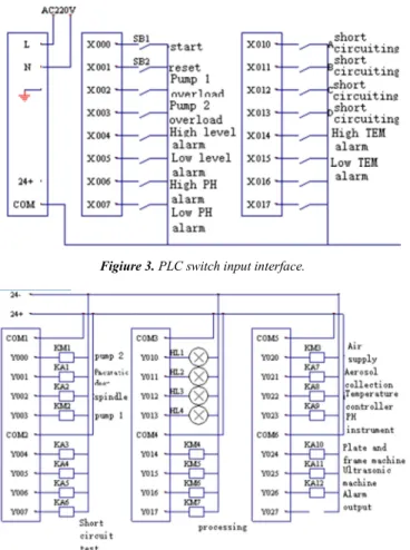
3.2. The Interface of PLC
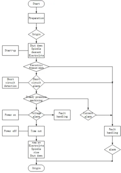
of PLC and the external hardware. Before designing the interface circuit of PLC, we must make clear the status of information exchange between PLC program and external hardware [11]. The design of PLC interface circuit includes the design of switching input interface circuit, switching output interface circuit and analog input interface circuit. The PLC switch input interface circuit is designed in the form of "DC sink point input", as shown in Figure 3. The advantage of sink input is that it does not need external power supply to provide input signal. The input power is leaked from the inside of PLC to the outside. Therefore, it is also called "leaky input" [18]. The output forms of PLC include relay coil output, DC transistor output and bidirectional thyristor output. Figure 4 is the output interface circuit of PLC relay. The output signals include relay coil, indicator lamp, alarm, etc.
Figiure 3. PLC switch input interface.
Figure 4. PLC switch output interface.
The system has 8 analog signals (4 voltage signals and 4 current signals) which need to be input into PLC for processing. The signal comes from the current signal of 0-20mA input from Hall voltage sensor transducer and Hall current sensor transducer, which conforms to the standard signal input of FX2N-4AD. Analog signal can be converted into internal operation of PLC through input of FX2N-4AD module of PLC [12]. Figure 5 is the PLC analog input interface circuit.
Figure 5. PLC analog input interface.
3.3. The Short-circuit Detection Circuit
Workpiece is connected with the positive pole in the electrolytic deburring process, and the tool is connected with the negative pole. Maintain a certain gap between the cathode and anode. The cathode is easy to contact with the protruding burr of the anode and is prone to short circuit. Before the cathode and anode are energized, the short-circuit detection circuit is connected. If there is a short circuit between the cathode and anode, the detection circuit will produce an alarm signal. At the same time, the connection of the electrolytic power supply is prohibited. Then the short circuit signal is processed by PLC. Short-circuit detection circuit can avoid the harm of short-circuit overload on power supply, and also can effectively avoid burns on workpieces.
Short-circuit protection circuit design as shown in Figure 6 shows that the voltage drop at both ends of diode D is 0.7V, and the voltage at the positive input end of operational amplifier IC can be continuously adjusted between 0 and 0.7V.
Figure 6. Short circuit detection circuit.
R0 is the resistance between the workpiece and the tool. V0 = 24V, R2 = 100, R1 = 10, V+ = 0.01V, turn on the relay KA, turn on the short circuit detection function of the station. When R0 is not connected, according to formula 1, V−>>V+, T-cut-off, coil is not conductive; when the cathode and anode are short-circuit, the resistance between electrodes R0 = 0.0005, V, operational amplifier IC and coil conduction. The contacts are connected to PLC to inform it that there is a short circuit between the workpiece and the tool in this position [13].
10 24
100 10
−= × + >> +
4. Software Design of Control System
Hardware is the physical execution of control system, and software is equivalent to the "brain" of control system. The function of the software is to carry out logical operation and sequential control according to specific schemes, and output the driving signals needed for hardware execution [14]. Scientific and effective software design can give full play to the function of hardware, and even make up for the deficiency of hardware function.
The software of the control system is modular design (Block-based design). In the design of control program, Mitsubishi PLC programming software GX developer is used. Ladder diagram language and sequence function diagram are selected for the type. The design of human machine page is based on page configuration software Easybuilder 8000.
4.1. The Preparation Module
This module should do some preparatory work before performing manual or automatic processing, such as the opening of air source, the opening of mist collection device, the opening of temperature controller and the opening of PH instrument, etc. These work are completed in the preparation module. Once the preparation is ready, the control system
allows manual processing or automatic processing functions. Compared with other modules, the module is relatively simple, and the relationship between the devices is relatively independent.
4.2. The Work of Analog Processing Module
This module includes the following aspects: acquisition of processing voltage signal (from four-station voltage transmitter) and processing current signal (from four-station current transmitter); realization of over-voltage monitoring and over-current monitoring; timing of charging time.
4.3. Automatic Processing Module
The PLC program of automatic machining module automatic processing module is designed by sequential function diagram. Figure 7 is the control process of the automatic processing module. The man-machine page design of the module is shown in Figure 8. After the preparation is ready, enter the automatic processing page. After judging that the system is in the original state and the starting conditions are satisfied, the system can click the "Start" button and call the module to execute the automatic processing process. Automatic processing pages also include monitoring of processing flow and process parameters.
Figure 8. Automatic processing page.
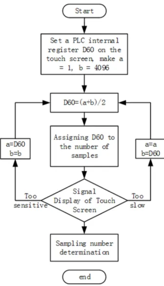
4.4. Software and Filter Design for Voltage and Current Signals
The display of processing voltage and processing current on the touch screen is unstable. Oscillograph is used to measure the dynamic waveform of the output signal of the acquisition module, which is shown as sawtooth wave signal. In hardware, the Hall sensor transmitter is modified, and RC filter circuit is added after the signal output to make the signal input
FX2N-4AD stable. Software is implemented through PLC program to achieve software filtering effect. The system adopts the software arithmetic average filtering method. Its basic principle is that in the sampling period T, the signal is sampled m times and the arithmetic average (the magnitude of the sampling number m determines the smoothness and sensitivity of the signal). As the effective sampling value y (k) at t=kT, it is calculated according to formula 2.
1 1 y( ) ( )
m
i
k y i
m =
=
∑
(2)The smaller the setting of sampling number, the closer the signal display is to reality, but the display is very unstable; the larger the setting of sampling number, the more stable the display is, but the signal display becomes dull, and the "over-voltage monitoring" function of the software is not sensitive enough. The choice of sampling number is very important, and its value can be determined according to the method in Figure 9.
5. Conclusion & Prospect
This paper analyses the electrochemical deburring processing technology, designed and implemented based on PLC and configuration technology electrochemical deburring machine control system, the configuration of PLC input/output interface connection, designed the control of main circuit and short circuit detection circuit, in accordance with the requirements of process design the control system of PLC program and human-computer interface, machine debugging results show that the system runs stably, ensure the machining accuracy and efficiency, to achieve good removal effect of burr.
The control system developed in this paper can meet the basic requirements of the electrolytic deburring machine tool, but there are still several aspects to be improved as follows: (1) simplify the hardware and optimize the layout of components. Optimize software, improve software openness and module versatility. (2) Using computer control technology to control the process parameters of electrochemical machining with fuzzy algorithm and self-adaptive control is of great significance to improve the processing accuracy, efficiency and surface quality [15]. (3) Expand its other functions, such as production management, production of workers'work logs, calculation of workers' total production and salary calculation.
Fund Projects
West Anhui University School-level Project WXZR201916; West Anhui University School-level Project WXXY2017119.
References
[1] Chen Yuanlong, Li Ming, Tang Huohong. Design of Control System for Electrochemical Deburring Machine Tool [J]. Modular Machine Tool and Automation Machining Technology, 2012, 54 (10): 63-65, 68.
[2] Ren Jing, Chen Jing. Current situation and development trend of burr removal abroad, [J]. http://www.cqvip.com.
[3] Xian Jieyu, Fu Xiuqing, Dry for the People, etc. Experimental
Study on Electrolytic Finishing of Gear Teeth [J]. Modern Manufacturing Engineering, 2016, 38 (12): 103-107.
[4] Mohsen M Daniali, Gholamreza Vossoughi. Intelligent active vibration control of constrained manipulators in robotic deburring [C]. International Conference on Industrial Mechatronics and Automation, 2009: 76-80.
[5] Hu Yifan, Fan Qingming, Cao Yan, et al. Study on the design method of cathode integral structure for high precision electrochemical machining of spur gear [J]. Electric machining and die, 2018, 53 (02): 29-34.
[6] S Sarkar, S Mitra, B hattacharyya. Mathematical modeling for controlled electrochemical deburring (ECD) [J]. Journal of Materials Processing Technology 2004 (147): 241-246.
[7] Gao Song, Shi Zhengji, He Ning. Design of power supply control system for high frequency pulse electrochemical machining [J]. Instrument technology, 2005 (4): 353-361.
[8] initial flight. MITSUBISHI FX series PLC programming and application [M]. Beijing: Electronics Industry Press, 2010.
[9] Eunjin Koh, Jongho Won, Changseok Bae. Vision-based Virtual Touch Screen Interface [J]. Consumer Electronics, 2008. 8: 1-2.
[10] Yi Hong Ke. Design basis and example of electrical control system [M]. Beijing: Machinery Industry Press, 2005.
[11] Li Ming. Design and Implementation of Control System for Electrochemical Deburring Machine Tool [D]. Hefei: Hefei University of Technology, 2012.
[12] Chen Yuanlong, Wang Tianjiu, Wanshengmei. Development of NC ECM machine tool based on PLC and touch screen technology [J]. Electrical processing and die, 2003 (3): 56-59.
[13] Li Ming. Design of control system of electrolytic deburring machine based on PLC [J]. Journal of shenyang university of technology, 2018, 37 (06): 44-48.
[14] Zhu Xunpeng. Design of the electrical system of the special machine tool for electrochemical deburring of inner cross-hole [J]. Combination machine tool and automatic processing technology, 2016, 58 (07): 63-66.