Designing, Developing, and Deploying a Small Footprint Low Frequency System for Positioning, Navigation, Timing, and Data Services
Chris Stout, Charles Schue, John Hartline – UrsaNav, Inc.
Abstract
Global Navigation Satellite Systems (GNSS), such as GPS and Galileo, are inherently vulnerable to interference, disruption, jamming, and spoofing, whether intentional or otherwise. GNSS is also subject to system failures and anomalies that could lead to degradation in service or a complete outage. Civilian markets, law enforcement, and the military community have also come to rely on GNSS for a variety of applications. Terrestrial-based, low frequency (LF) Position, Navigation, Timing, and Data (PNT&D) systems have historically required a large footprint, significant infrastructure, expensive equipment, and costly operations and maintenance. New LF systems are technologically-advanced and provide a low-cost alternative to help lessen the dependence on GNSS and provide accurate and reliable PNT&D services irrespective of the availability of GNSS.
In this paper we present an innovative, small footprint, terrestrial positioning system based upon the Enhanced Loran (eLoran) system that is cost-effective, easily transportable, and rapidly-deployable. While the system is designed to broadcast eLoran, it can be applied to any LF broadcast transmissions, including VLF and MF transmissions. The system can be used as a standalone site or in conjunction with existing sites, other deployable sites, or other technologies to provide PNT&D services. We discuss various options for scaling the system equipment upward or downward in power and size to
fulfill a range of operational requirements. We present the design and development of our system and the field test results of a deployment. We discuss all aspects of the system including: the transmitter; timing and signal generation equipment; command, control, and communications capability; ancillary equipment; backup/uninterruptible power; transmitting antenna options; and the equipment enclosure, container, or shelter. We will show that our proposed solution is significantly smaller and more economical than previous generations. The technology underlying the system is state-of-the-art, robust, reliable, and affordable, and represents a quantum leap forward in meeting the accuracy, integrity, continuity, and availability requirements for PNT&D services, including maritime Harbor Entrance Approach (HEA) and aircraft Non-Precision Approach (NPA) requirements. Our proposed system: is a cost-effective backup to GNSS; is completely interoperable with and independent of GNSS; has different propagation and failure mechanisms; has significantly superior robustness to radio frequency interference and jamming; and is seamless across all modes (aviation, maritime, land-mobile, location-based, and precision time/frequency). It also includes pointing (compass/heading) capability. The application of our solution can also be extended to Satellite Based Augmentation Systems (SBAS).
1.0 Introduction
During a national security conference in January 2010 in Washington, DC, the Chief of Staff of the U.S. Air Force, General Norton Schwartz, stated: “It seemed critical to me that the joint force reduce its dependence on GPS-aided precision navigation and timing” [1]. An over-reliance, or “addiction,” to satellites could result in chaos. GNSS is inherently vulnerable to interference, disruption, jamming, and spoofing, whether intentional or otherwise. GNSS is also subject to system failures and anomalies that could lead to degradation in service or a complete outage.
The international community has also expressed concern about the over-reliance on GNSS-provided PNT services. In May 2010, the International Civil Aviation Organization (ICAO) Navigation Systems Panel (NSP) working group developed a flimsy documenting “work being accomplished by the U.S. Federal Aviation Administration (FAA) to assess alternatives for providing PNT services when GNSS is not available due to RFI” [2]. And during the 49th International Association of Marine Aids to Navigation and Lighthouse Authority (IALA) Council Meeting in June 2010, a question was directed to industrial members as to what industry is working on or thinking about regarding the ever increasing reliance on GNSS-based navigation systems. The council recommended that “IALA should encourage the development of a global redundant system, or combination of systems, independent and dissimilar to GNSS, to facilitate e-Navigation” [3].
Terrestrial-based, LF PNT&D systems have historically required a large footprint, significant infrastructure, expensive equipment, and costly operations and maintenance. New LF systems are
technologically-advanced and provide a low-cost alternative to help lessen the dependence on GNSS and provide accurate and reliable PNT&D services irrespective of the availability of GNSS.
We explored how current technology could be applied in the development of a cost-effective, small footprint, rapidly-deployable, and easily transportable Loran system in a previous paper presented at the International Loran Association (ILA33) Technical Symposium in Tokyo, Japan [4]. At the core of any LF system is the transmitter, and during the Royal Institute of Navigation NAV08/ILA37 conference in Westminster, London, we introduced the prototype Next Generation LF transmitter, a quantum leap forward in implementing a modern Loran system [5].
A joint effort between UrsaNav, Inc. and Nautel, Inc., the NL Series transmitter addresses the issues of smaller Size, Weight, and (Input) Power (SWAIP) necessary for a cost-effective, deployable system. We also introduced the (e)Loran-in-a-Box (ELB) concept outlining various small footprint configurations for housing the system components including: the transmitter; time recovery and signal generation equipment; command, control, and communications capability; ancillary equipment such as HVAC; and backup power.
The NL Series transmitter technology provides the opportunity to explore a variety of options for the transmitting antenna, the remaining critical component in the development of a small footprint eLoran system. During the ILA38 conference in Portland, Maine, we presented a prototype antenna designed to operate at a range of 25 nautical miles [6], [7].
1.1 eLORAN and Its Uses
Enhanced Loran, or eLoran, is a modernized, vastly improved version of Loran-C or “standard” Loran that was initially developed in the 1940’s. eLoran is an LF system that uses terrestrial-based stations to provide user receivers with reliable, accurate, all-weather PNT&D services independent of, and complementary to GNSS, such as GPS, Galileo, and GLONASS. Although not as precise as GPS, tests have indicated that eLoran meets or exceeds the accuracy, availability, integrity, continuity, and coverage requirements necessary to achieve 8-20 m maritime Harbor Entrance Approach (HEA) and aviation RNP 0.3 Non-Precision Approach (NPA) levels of performance [8]. Several countries have identified eLoran as the best backup for all modes of transportation [9]. U.S. Government reports have concluded that eLoran is the best backup and means to mitigate the impact of a GPS outage because eLoran is independent, complementary, and seamless across all modes: aviation, maritime, location-based, land-mobile, and precision timing/frequency [10], [11], [12], [13].
Despite the findings, the U.S. Coast Guard (USCG) began terminating the Loran-C signal on February 8, 2010 [14]. In its continuing efforts to assess the need for a domestic national system to serve as a backup to GPS, we are confident the U.S. Department of Homeland Security will conclude that a terrestrial-based LF system will be needed. In this case, the results and findings of our work will provide significant benefits to the U.S. Government in implementing a technologically-advanced, cost-effective system to mitigate the effects of a degradation or loss of GPS service. The results of our work also have direct application to international countries who
continue to operation Loran-C and eLoran and could benefit from reduced costs and the numerous benefits that result from implementing new and improved technology. 1.2 Previous Small Footprint Systems The idea of small footprint Loran systems is not new. There have been several historic efforts to deploy versions of Loran to support military missions, provide an additional aid for maritime navigation, and for various “tactical” reasons. Loran-D, the Air Transportable Loran System (ATLS), the St. Mary’s River Loran-C Mini-Chain, and Racal Positioning Systems’ Pulse/8 are all such examples. However, technology has significantly improved since the last small footprint Loran system was phased out of service in the mid 1980s. This inspires a renewed effort to explore LF systems for providing reliable PNT&D services in support of GNSS.
1.3 Requirements for a Small Footprint eLoran System
A small footprint eLoran system, depending on its ultimate use, would be capable of providing fixed, en-route, and terminal position, navigation, and timing solutions, along with any associated data channel capabilities to government and commercial users at a lower cost than installing a fixed system. Some of the basic requirements for a small footprint system are:
• Rapid installation and de-installation (when used as a temporary or tactical solution);
• Small SWAIP requirements;
• Significantly lower cost than a fixed system;
• Ease of use that supports unmanned operation;
• Piece-wise equivalent to a fixed system in signal specification and enhanced transmission formats;
• No, or very limited, external cooling; • An easily deployable configuration; and • Equivalent reliability and robustness to a
fixed system.
1.4 Overview of the Small Footprint eLoran System
A typical small footprint eLoran system consists of the following components or “suite” of systems:
• Appropriately sized Transmitter,
• Time Recovery and Signal Generation equipment,
• Command, Control, and Communications Capability,
• Ancillary equipment (i.e., HVAC), • Backup/uninterruptible power, • Transmitting antenna, and
• Equipment enclosure, container, or other adequately sized shelter.
If commercial prime power is not available, then prime generator, or combined power generation would most likely be housed in an appropriately sized separate mini-storage container, such as a QUADCON or TRICON. 2.0 NL Series Transmitter
UrsaNav has worked with Nautel, Inc., a world-class high-power RF engineering company, to develop LF transmitters that eclipse currently available technology. The challenge was how to transmit low frequencies, in this case in the Loran band, into physically short antennas, with their associated significant reflected power, while considerably reducing SWAIP. The solution was the Nautel Loran (NL) Series transmitter. The building block of the NL Series transmitter is a Class D RF amplifier, shown
in Fig. 1, with Nautel’s patent pending pulse power recovery technique that reuses reflected power from the antenna that is normally dissipated as heat. With an overall efficiency typically 70% or better, reflected energy is recycled, thereby reducing input power, cooling, and ventilation requirements and associated costs. The exceptional efficiency, regardless of antenna height, and low maintenance overhead, makes the innovative NL Series transmitters extremely cost effective to own and operate.
Figure 1. Nautel NL Series RF amplifier power module
2.1 Proof of Concept Development
In April 2008, we successfully tested a 50 kW Effective Radiated Power (ERP) proof-of-concept transmitter at Nautel’s facility in Halifax, NS. Fig. 2 shows the major components of the prototype transmitter.
Figure 2. Nautel NL Series proof-of-concept prototype
The transmitter was tested at over 600 Pulses-Per-Second (PPS) into a simulated 191-m (625-ft) Top-Loaded Monopole (TLM) antenna on combinations of several North American Loran rates.
In May 2008, the NL Series proof-of-concept transmitter was independently tested by Alion Science & Technology, Inc., in support of the USCG Academy, and Peterson Integrated Geopositioning, at the USCG Loran Support Unit (LSU) in Wildwood, NJ. The results were presented at the Royal Institute of Navigation (NAV08)/ILA37 conference in Westminster, London and highlighted the transmitter’s noteworthy performance. Alion’s testing showed that the NL Series transmitter has “many advantages for efficient and cost-effective eLoran operation” [15].
2.2 Introducing the Production NL Series Transmitter
The final production design of the NL Series transmitter was unveiled at ILA38 in October 2009. Fig. 3 shows the Nautel NL40 transmitter, which is capable of 270 kW ERP when driving a 191-m (625-ft) TLM.
Figure 3. Nautel NL40 production eLoran transmitter
The NL Series combines 24 hot-swappable RF modules in each power cabinet with easy front panel access. The modules are configured as 20 active, two spare, and two damping. The NL Series can experience significant RF amplifier failure with no change in pulse shape or timing. This allows the NL Series transmitter to stay on the air and eliminates the need for emergency site visits. Since most active components have on-line spares or are hot-swappable, repairs or module replacement can be performed whenever it is convenient. Along with the RF modules, the NL Series features a fully parallel, redundant architecture on all active components and offers:
• Redundant power amplifiers, • Redundant Exciters,
• Multiple parallel/redundant fans, • Redundant low voltage power supplies, • Failsafe manual and remote control,
• Redundant switch mode power supplies, and
• 10% power amplifier overhead.
The NL Series transmitter features a 43-cm (17-in) color LCD touch-screen Advanced User Interface (AUI) with a range of control, monitoring, and diagnostic features. The AUI includes data acquisition and diagnostic functionality, comprehensive monitoring and control, and logging of all functions. Users can access status, controls, alarms, logs, and reports anywhere internet access is available. The NL Series transmitter is easily scalable using combining techniques that have been proven reliable in high-availability fielded systems for over 25 years. Fig. 4 shows the NL Series ranging from the NL20 to the NL100, which provide a minimum of 125 kW and 725 kW ERP, respectively. Further scaling results in even higher powered transmitters, starting with the NL160 at over 1.15 MW ERP. The NL Series also features a software configurable pulse shape to meet
the requirements of future modulation techniques.
Figure 4. Nautel’s eLoran line of transmitters
The NL Series transmitter is designed to withstand harsh environments anywhere in the world and is ideally suited for unattended, automatic, or remote controlled operation. Field experience with similar Nautel technology indicates a Mean-Time-Between Failure (MTBF) in excess of one million hours for the NL Series transmitter. Nautel’s redundant architecture, with built in spare modules, not only maximizes on-air continuity but greatly minimizes spare requirements. 3.0 Time Recovery and Signal Generation Thanks to the efforts of the Loran Recapitalization Project, the USCG was able to take advantage of technological advances and make significant improvements to Loran timing, signal generation, and control. The Timing and Frequency Equipment (TFE) suites used at USCG Loran transmitting stations (LORSTA) can be re-packaged and used in the small footprint eLoran system. The TFE consists of the following components:
• Timing source, • Timing front end,
• Loran signal generation, and • Measurement and control.
Three Cesium standards have historically been used at USCG LORSTAs. Although a cesium provides the best performance for a field-able atomic standard, its cost and slightly larger SWAIP could be prohibitive in a small footprint eLoran system. A rubidium can provide similar performance in a smaller package at less cost than a cesium; however, a rubidium has a reduced holdover performance when the clock is not externally steered or “disciplined.”
The timing front end provides an external reference that allows the transmitter to be synchronized within 10 ns RMS of UTC (USNO). Typically an indirectly coupled GPS receiver is used as the timing front end; however, a Two-Way Satellite Time Transfer (TWSTT) front end can provide GPS-independent time synchronization.
Signal generation occurs in a set of Field Programmable Gate Arrays (FPGA) in the Loran Integrated Timer and Signals Unit (LITS). The LITS unit accepts a 5 MHz signal from the frequency reference and generates transmitter drive and ancillary signals with strict phase relationships based on the stable clock [16]. The signal generator also has the ability to control the pulses (data modulation, blink, cross-rate blanking, phase adjust, etc.) based on commands from the measurement and control component.
The measurement and control component, consisting of a modular chassis with appropriate modules, continually monitors and verifies the Loran signal to ensure the necessary performance and integrity required of Loran systems. The measurements are processed to ensure the transmitted pulses have the proper phase relationship to UTC, are consistent within the pulse groups, and maintain acceptable short term frequency stability. Control of the Loran signal is applied via commands to the LITS.
4.0 The Transmitting Antenna
The robustness and efficiency of the NL Series transmitter provides the opportunity to explore antenna configurations that previously may not have been possible. The small footprint eLoran system could drive historical, existing, or planned antenna configurations, depending upon the required ERP and deploy-ability, including:
• 152- (500-), 191- (625-), 213- (700-), 219- (720-), 259- (850-), or 411-m (1350-ft) TLM,
• Top-Inverted Pyramid (TIP),
• Sectionalized Loran Transmitting Antenna (SLT),
• 88-m (290-ft) to 110-m (306-ft) GWEN, • “Antennas of Opportunity” (e.g.,
re-purposed AM antennas),
• 91-m (300-ft) Tilt-up Tower (AN/TSA-17, or equivalent),
• 91-m (300-ft) Goodyear or Birdair Type inflatable tower,
• Up to 91-m (300-ft) Andrew Tower Corporation telescoping tower,
• 88-m (290-ft) “jack-up”, Anthorn, Cumbria “T-type”, or
• Tri-tethered, aerostat-, airship-, or balloon- supported.
4.1 Designing the Antenna
In 2009, we contracted Nautel to design and develop a suitable antenna for field testing of the small footprint eLoran system. To help reduce costs and expedite a short-duration field test, we chose the following design conditions for the transmitting antenna:
• Operating range of 25 nautical miles,
• Field Strength of 55 dBµv/m at ground level (assuming ground conductivity of 1 mS/m),
• Transportable using common carriage, such as moving vans, trailers, small cargo aircraft, etc.,
• Erectable within 4-6 hours without the use of heavy or special equipment,
• Able to withstand a variety of environmental conditions worldwide, and • Minimum physical size and footprint.
Given the short operating range, the ground conductivity has no significant impact on the signal propagation; however, it does affect the antenna’s equivalent ground loss resistance and hence its efficiency. Because the wavelength of the transmitted signal is three kilometers, historical Loran systems have generally used large antennae. The challenge is how to get as much capacitance as possible as high as possible. Top loading antennas are typically used in order to optimize effective height and efficiency. Typical fixed Loran stations with large antennae operate at power levels from 250 kW and higher. We determined that a peak radiated power of only 40 W would produce a field strength of 55 dBµv/m at 25 nm.
We did not consider base insulated towers because of their excessive weight and the time and expertise needed to construct them. Nautel engineers proposed the following structures commonly used in the low and medium frequency bands:
• 23-m (75-ft) fiberglass whip with 6 X 21-m (70-ft) Top Loading guy Elements (TLE) and sixty 18-m (60-ft) ground radials,
• “Tee” antenna 18-m (60-ft) high by 46-m (150-ft) long with twenty 27-m (90-ft) and eighteen 41-m (135-ft) ground radials, and • Two inverted cone or TIP designs: 18-m
(60-ft) cube and 21-m (70-ft) cube with thirty-six 18-m (60-ft) and thirty-six 21-m (70-ft) ground radials, respectively.
Nautel engineers evaluated the antenna designs using the GNEC-4 antenna analysis software and compared the peak antenna voltages. Each of the antennas uses wire as its radiating element to increase capacitance while minimizing weight. When elevated to high RF potentials, thin wires exhibit a condition whereby the air surrounding the wires breaks down causing the onset of corona. The onset voltage for thin wires occurs above 50 kV. The 21-m (70-ft) inverted cone design, shown in Fig. 5, was the only antenna to have a peak voltage (46 kV) below this limiting factor and was chosen as the prototype antenna design for the small footprint eLoran system.
Figure 5. Inverted cone or TIP antenna design
The total antenna resistance and the overall Q value of the antenna determine the required drive level from the transmitter. With a Q value of approximately 480, the 21-m (70-ft) inverted cone antenna requires an input voltage of approximately 1,800 V (2,500 V peak) to produce the necessary 10 W radiated power (40 W peak). We determined the 50 kW proof-of-concept transmitter, capable of 3,000 V output, could meet this requirement. Because of the high Q, a separate Antenna Tuning Unit (ATU) positioned at the apex of the antenna is necessary.
4.2 Constructing the Antenna
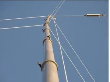
Four lightweight masts that could be easily erected were required to support the wires of the antenna and to meet the requirements for transportability and erect-ability. A telescopic fiberglass whip with a mechanical crank handle was an initial favorite until we learned it was made of carbon fiber which burns when exposed to high intensity electric fields. We subsequently selected 21-m (70-ft) telescopic masts made from aluminum alloy that are pneumatically extended in seven sections (not including the base section) using a 12 VDC air compressor. Fig. 6 shows the top of the mast with its telescopic sections retracted and locking rings for securing the extended sections.
Figure 6. 21-m (70-ft) telescopic mast (retracted)
Each mast is triply guyed at three heights using pre-stretched polyester ropes connected to the mast using D-rings. The guys are connected to 76-cm (30-in) anchors hammered into the ground. The maximum head load for each mast is 20 kg (45 lbs), with each of the four required to support one quarter of the total weight of the antenna wires and insulators with the necessary guy strain to minimize sag in the wires. We selected stainless steel wires and lightweight insulators as a compromise between weight and maximum workable voltage. Each mast is designed to sustain 22 m/s (50 mph) winds when properly guyed.
The various components of the antenna are packaged in 12 wooden crates with a total volume of 7.4 cubic meters (260 cubic feet) and a total weight of 1,043 kg (2,300 lbs). This does not include a “support crate” containing spare components, tools, and analyzing equipment. Fig. 7 shows 9 of the 12 antenna crates loaded onto a 6-m (20-ft) by 2.5-m (8-ft) trailer.
Figure 7. Antenna crate loading on a towable trailer
4.3 Antenna RF Hazards
IEEE Standard C95.1-2005 provides recommendations to protect against the harmful effects in human beings exposed to electromagnetic fields in the frequency range from 3 kHz to 300 GHz. The E-field and H-field limits for the Loran frequency of 100 kHz when averaged over a period of six minutes are 614 V/m and 163 A/m, respectively. An analysis of the radiation values for the inverted cone antenna showed peak values well below the limits and not posing a safety hazard at any point close to the center of the antenna or the ATU.
5.0 Equipment Enclosure
NL Series transmitters are typically at least one-half the size of competing solid state high power Loran transmitters. As shown in Fig. 8, the NL Series transmitter, along with the necessary TFE and backup power equipment, can be constructed entirely within the confines of an ISO standard 6-m (20-ft)
container, or equivalent space. ISO containers, often referred to as CONEX boxes, are typically 6-m (20-ft) to 12-m (40-ft) long, 2.4-m (8-ft) wide, and 2.4-m (8-ft) or 2.6-m (8.5-ft) tall. The NL Series transmitter has a depth of 1.1-m (3.5-ft) and a height of 1.8-m (6.0-ft), with the width ranging from 1.7-m (5.5-ft) to (7.6-m) 25.0-ft for the NL20 and NL160, respectively.
Figure 8. NL Series transmitter CONEX box mock-up
Fig. 9, 10, and 11 show representative enclosures for a small footprint eLoran system.
Figure 10. Shelter One industrial shelter
Figure 11. Gichner trailer enclosure 6.0 Field Testing the eLoran System 6.1 The Test Plan
We worked with the USCG Navigation Center (NAVCEN) in Alexandria, VA and the USCG LSU to obtain the necessary approvals to conduct on-air testing from October 19-22, 2009. We were granted permission to transmit Loran signals on the 5030 (Master and Secondary) and 9960T LSU test rates, including broadcasting 9th pulse data, i.e., the Loran Data Channel (LDC). Since we would be using the LSU test rates, we were required to conduct our testing in Wildwood, NJ and were given permission to set up our system at the LSU. We coordinated our testing activities directly with the LSU and the NAVCEN.
6.2 Transportation
To keep testing costs low, we chose to rent a moving truck that approximated the interior dimensions of a CONEX box. Fig. 12 shows
the Straight Truck we rented from Ryder System, Inc.
Figure 12. Ryder eLoran transmitter truck The truck included a rear hydraulic lift gate and ramp and a side door. The truck’s interior space measured 7.9-m (26-ft) long by 2.4-m (8-ft) wide by 2.6-m (8.5-ft) high. To create a closed interior for protection from the elements and to facilitate environmental control of the equipment, we fabricated false walls for the rear and side openings of the truck. We designed the false walls so the air conditioning (A/C) ducts would run through the side door opening and the antenna feed line could be run through either the rear or side of the truck. Fig. 13 shows the false wall for the rear of the truck before it was painted white. The door in the false wall and the slide-out ramp provide entry into the transmitter truck enclosure.
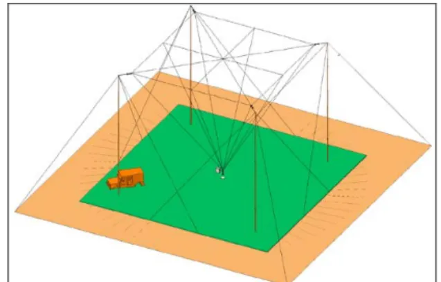
Fig. 14 shows the planned positioning of the transmitter truck in relation to the antenna masts and top guy wires. We positioned the truck close enough to use a flexible, low-profile antenna feed line and still avoid obstructing any of the guys.
Figure 14. Transmitter truck positioning for connecting to the inverted cone
antenna
The 7.9-m (26-ft) Ryder truck provided more than adequate space for loading all the components of the small footprint eLoran system, including installation and support equipment. Fig. 15 shows the storage of the transmitter and antenna crates and the portable 5-ton A/C unit.
Figure 15. Interior loading of the Ryder Straight truck
6.3 Power and Ancillary Equipment
We calculated the power requirements of our eLoran system, including the portable A/C unit, and determined that a 220 V, 20 kW
generator was the easiest size to rent at our test location. Fig. 16 shows the generator positioned next to the transmitter truck.
Figure 16. Caterpillar 220V, 20 kW diesel generator
Although it far exceeded our requirements – especially given the colder weather precluded the need for A/C – it was available locally at a good price, and delivery was included.
6.4 Site Location
We originally planned to set up our test system at the LSU. As seen in Fig. 17 the inverted cone antenna masts require a 24-m (80-ft) square area, but we needed a 49-m (160-ft) square area to accommodate the outermost guy points.
Figure 17. Inverted cone antenna dimensions
We surveyed two possible locations at the LSU but neither provided the required clear area. The larger of the two sites also presented a challenge to anchoring since the outermost guys would have to be positioned in sand dunes. Since this was our first time testing the small footprint eLoran system, we did not want to add any additional challenges in erecting the antenna.
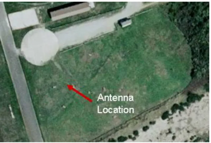
We worked with the LSU to identify an alternate site and obtained permission to use an open field at the USCG Training Center (TRACEN) in Cape May, NJ. Fig 18 is an aerial view of the test site approximately 137-m (450-ft) long by 73-137-m (240-ft) wide providing ample room for setting up the eLoran system. The marker denotes the position of the center of the antenna.
Figure 18. Test site location at the USCG TRACEN
The circular area to the north is a concrete pad which served as an equipment staging and storage area. There was also a restroom facility nearby. Fig 19 shows a view of the test site from the concrete pad. Although this area required anchoring the guys in sandy soil, it provided a relatively level test location free from obstructions.
Figure 19. View of the test site from the north
6.5 Setting up the Antenna
We arrived on-site on October 17, 2009, allocating ourselves two days to erect the antenna and set up the transmitter equipment so we could begin testing on October 19. The prototype inverted cone antenna was designed to be erected in 4-6 hours without any heavy or special equipment and with adequate personnel for simultaneously erecting all four masts. However, our team consisted of five people and we could only erect one mast at a time. Because this was our first time erecting the antenna in the field, we allocated ourselves two days. As it turned out, the cold temperatures, e.g., 8-11˚C (46-52˚F), rain, and strong wind conditions, e.g., 5-10 m/s (11-23 mph) with gusts up to 14 m/s (30 mph), provided some challenges. Even with the learning curve, limited number of personnel, and poor weather, we were able to fully construct the antenna and begin testing in slightly less than two workdays. The first step in erecting the antenna was to off-load the crates and position them in the test area. Although our team could have physically carried each of the crates into position, we used a pickup truck to expedite the process, as shown in Fig. 20.
Figure 20. Off-loading the antenna crates Before we could erect the antenna, we established the center point of the inverted cone for the base insulator plate. We then used a pre-fabricated length of rope with markings to determine the mast and guy anchor points. We placed two crates at each mast point, one containing the telescopic mast and the other containing the guys and anchor spikes/stakes for that mast. Fig. 21 shows the positioning rope and one of the mast base plates in position.
Figure 21. Marking the mast and anchor positions
Although the ground consisted of a layer of grass and soil, we reached sand approximately 10-cm (4-in) below the surface and the water table around 61-cm (2-ft). The
antenna is designed to use galvanized steel anchors spikes; however, given the poor soil conditions, wetness of the ground, and strong winds, we used a specially designed aluminum plate to provide additional support to each anchor. Fig. 22 shows the steel anchors before and after we drove them into the ground, along with the additional support piece.
Figure 22. Antenna guy anchors and anchor supports
Since the four outermost guy anchors support the most strain from the center of the antenna and since they serve as the anchor point for the top and middle guys, we buried an anchor plate instead of using the anchor spike. Fig. 23 shows the anchor plate buried approximately three feet below the surface positioned at a 30 degree angle to the horizontal to provide the correct guy lead.
Figure 23. Outermost guy anchor plate After we placed the anchors, we set the telescopic masts and attached the low point guys, as shown in Fig. 24.
Figure 24. Antenna mast base section and guys
The antenna masts are designed to be extended in 14 m/s (30 mph) winds with just the base section supported. However, we erred on the side of caution and used three of our team members to man the guys as each mast was extended. Extending the masts requires a person to control the electric compressor and another person to climb to the top of the base section and tighten the section collars as the mast is extended, as shown in Fig. 25 and Fig. 26.
Figure 25. Positioning to extend the mast
Figure 26. Extending the mast
After extending the four masts and tensioning the guy wires, the team split up with two people laying the ground radials and three people setting up the antenna wires. The 36 ground radials consisted of 12 AWG solid bare copper wire 21-m (70-ft) in length connected to the base plate spaced 10˚ apart. We used a pre-fabricated length of rope to determine the correct spacing between the ground radials. Fig. 27 shows the ground radials attached to the base insulator plate.
Figure 27. Ground radials attached to the base plate
The antenna wires/radiating elements and top insulators were arranged on the ground in an inverted cone shape before being raised
in the air. Fig. 28 shows the connector for the radiating elements. The connectors are located near the tip of each mast and form the four corners of the inverted cone.
Figure 28. Antenna corner connection point
The antenna was raised using a nylon halyard at each mast until the top insulators were approximately eight feet from the tip of the mast. This provided a balance between the strain on the mast and the sag in the antenna wires with the objective to raise the wires as high as possible with as little sag as possible. As was expected, as the antenna was raised, the mast tips bent inwards, as shown in Fig. 29, so we continuously monitored the strain and made adjustments to the guys to keep the mast straight.
Figure 29. Strain on the mast due to the antenna
We next attached the apex of the antenna to the base insulator and connected the ATU, as shown in Fig. 30.
Figure 30. Connecting the antenna to the ATU
As previously discussed, since the antenna had such a high Q (≈480), an additional tuning unit was needed in addition to the tuning unit built into the NL Series transmitter. Fig. 31 shows the inside of the ATU enclosure. A motor was installed so the ATU tuning components could be operated from inside the transmitter truck.
Figure 31. Inside view of the ATU
Given the moderate wind conditions, we decided to replace the synthetic-rubber base insulator with an oil-filled ceramic insulator, as show in Fig. 32. The heavier ceramic
insulator provided added weight at the base of the antenna to help steady the radiating elements/wires.
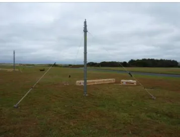
Figure 32. Oil-filled ceramic base insulator Fig. 33 shows the erected small footprint eLoran antenna.
Figure 33. 21-m (70-ft) inverted cone antenna
6.6 Setting Up the Transmitter Equipment We used the Nautel 50 kW proof-of-concept transmitter, shown in Fig. 34, to drive the prototype inverted cone antenna. The 50 kW transmitter supplies the required 2,500 V of
input power producing 40 W of radiated power from the antenna to meet our 25 nm operating range requirement.
Figure 34. Setting-up the Nautel 50 kW transmitter
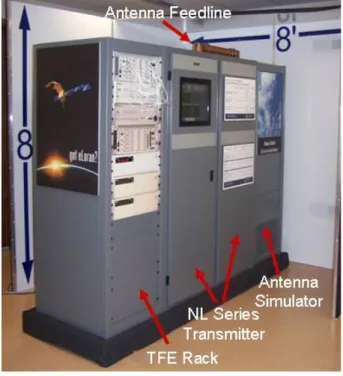
The transmitter ships in a single crate containing the amplifier and control rack, and the filter and antenna tuning/coupling rack. The TFE rack and the antenna simulator are crated separately. To minimize costs, and since redundancy and backup was not a high-priority during the field test, we used one-half Symmetricom (formerly Timing Solutions, Inc.) TFE consisting of a:
• 5071A Cesium Beam Oscillator with standard tube,
• Loran Integrated Timer and Signals (LITS) unit, and
• 2000 Series chassis, modules, and software.
Fig. 35 shows the TFE rack, Nautel transmitter, and antenna simulator positioned in the transmitter truck. Note that there is plenty of space for the operational equipment, spares, test materials, storage,
and even a “picnic” work table in the 7.9-m (26-ft) truck.
Figure 35. Positioning of the eLoran transmitter components
We used 18 meters (60 feet) of Heliax cable to connect the transmitter to the antenna. Fig. 36 shows the Heliax connected to the ATU.
Figure 36. Heliax connected to the ATU We used the antenna simulator to test the transmitter prior to connecting it to the antenna to ensure all components worked properly following transport.
Fig. 37 and Fig. 38 show the completed set-up of the small footprint eLoran system.
Figure 37. Completed transmitter truck set-up
Figure 38. Completed small footprint eLoran system
7.0 Performance and Test Results
We conducted our testing from October 19-22, 2009 and transmitted our first signals at 1200L on October 20th. We opted to run the transmitter power supply at 370 volts, producing an ERP of 38 W RMS at pulse peak. In comparison, the Nautel transmitter outputs an ERP of 50 kW when driving a 191-m (625-ft) TLM. We operated the trans191-mitter single-rated on 8090M, 5030W, and 9960T, and dual-rated on 8090M and 5030W. We
broadcasted LDC on 5030W and 9960T. Fig. 39 shows transmissions on 8090M.
Figure 39. Transmitting on 8090M We used a Loran monitor receiver to monitor the transmitted signal and set up the equipment in parking lot areas at two test sites. Fig. 40 shows the test site locations nd maximum signal strength and SNR raw data values measured at those locations. a
Figure 40. Test site locations and
ditional locations at much greater inc
• Monitor Station
b (see Fig. 42),
328 nm: LORSTA Carolina Beach, NC; SNR = +1 db.
measurements Several ad
distances were also able to track our signals luding:
• 80 nm: vehicle crossing the Francis Scott Key Bridge in Baltimore, MD (see Fig. 41), 115 nm: Loran
(LORMONSTA) Sandy Hook, NJ; SNR = +6 d
• 243 nm: LORSTA Seneca, NY; SNR = +1 db,
• 263 nm: LORSTA Nantucket, MA; SNR = -2 db, and
•
Figure 41. Tracking the eLoran signal in Baltimore, MD
Figure 42. Tracking the eLoran signal at LORMONSTA Sandy Hook, NJ
Because some of the receivers used during the test required a master-secondary pair for normal operations, we configured the NL Series transmitter to operate dual rated on 5030M and 5030W (approximately 338 PPS). This provided the opportunity for us to test the NL Series transmitter over long periods at high duty cycles. The NL Series transmitter is designed to recover the excess energy instead of dissipating it as heat, achieving more efficient use of the power. 300 PPS has been the typical limit for previously designed and in-service transmitters. The current version NL Series transmitter comfortably operates at up to 700 PPS, ensuring flexibility to meet the needs of future requirements. Fig. 43 shows the NL Series prototype transmitter operating dual rated on the 5030 rate. To our knowledge, this was the first time Loran transmitter has been operated at over 300 PPS.
a
Figure 43. NL Series broadcasting 5030W
ve creased the distance at which we were able
ta.
PNT&D services to sers who require GNSS independence.
airports, key assets, etc.,
• d crime fighting, e.g.,
• NSS
and mountainous terrain,
• source
Transmission of Satellite Based
area on the eastern seaboard: New York, Philadelphia, Baltimore, and Washington, DC.
and 5030M
Based on our results and raw test data, the small footprint eLoran system was able to broadcast a signal that could be used for PNT purposes out to at least 25 nm. We were also able to successfully receive and demodulate the LDC data. We anticipate that modulating additional pulses would ha in
to receive and demodulate the LDC da
8.0 Potential Uses and Scenarios
There are many potential uses for a small footprint eLoran or LF system as a means to augment and backup GNSS, provide PNT&D services where GNSS is degraded or unavailable, or provide
u
Potential uses include:
• Critical infrastructure protection for ports, harbors,
• High-profile events such as the Olympic Games,
Interference-enable
car theft, border crossing, tracking felons, and toll “cheating,”
Military operations subject to G unavailability, e.g., triple canopy, jamming scenarios,
Wide-area or localized timing providing
+/- 30 ns to UTC (Stratum 1), and •
Augmentation System (SBAS) information. As we demonstrated in our testing, it takes minimal time and effort to set-up a small footprint LF system. Increasing the signal coverage area is a straightforward task and would provide an additional means of obtaining PNT&D services independent of GNSS. Fig. 44 shows the areas benefiting from LF coverage out to 115 nm from our test site, including New York Harbor; Philadelphia, PA; Delaware Bay; Baltimore, MD; Chesapeake Bay; and the Washington DC metropolitan area. This small footprint system, or one similar to it, if moved NW approximately 40 km (25 mi), could provide critical backup timing service to four of the largest metropolitan
Figure 44. eLoran coverage out to 115 nm The importance of including an independent backup system when providing mission critical and safety of life services is currently being highlighted in the aviation community. On April 3, 2010, the service provider for the FAA’s Wide Area Augmentation System (WAAS) lost the ability to control the orbit of one of the two WAAS GEO satellites. The satellite will drift out of usable orbit within two to four weeks and once out of usable orbit, WAAS service will no longer be available for users in northwest Alaska [17]. While none of the 16 airports in the affected area has published WAAS-based localizer performance with vertical guidance (LPV), users in the service area of the remaining satellite, e.g., U.S., Canada, and Mexico, will be without a backup. Additionally, if a WAAS GEO uplink station switchover occurs, typically 3-5 times per year, it may take up to five minutes to restore service at the 2,037 airports with published LPVs. This situation could have been mitigated with technology proposed in this paper. The use of Loran to broadcast WAAS messaging system information has been investigated and it was found that the Loran system can provide backup WAAS coverage over the entire
continental U.S. and all of Alaska [18]. The use of an LF system can increase the availability and coverage of SBAS while providing an independent backup.
9.0 Conclusions and Future Work
The results outlined in this paper have demonstrated how state-of-the-art technology can be applied to implementing a small footprint, rapidly deployable, easily transportable, and cost-effective LF PNT&D system. In a short time, we took this idea from conceptual design to proof-of-concept prototyping of various components to successful field-testing of a complete small footprint eLoran system.
Although the focus of these efforts has been eLoran, the technology can be applied to other LF systems being considered for various PNT&D solutions, particularly in those instances where GNSS is degraded or unavailable. A small footprint LF system would be capable of supporting multiple missions (e.g., eLoran, emergency/data communications, subsurface/submarine broadcast), multiple modes (e.g., aviation, maritime, land mobile, location-based time & frequency), and multiple signal formats (e.g., Pulse Position Modulation, Supernumary Interpulse Modulation, and Intrapulse Frequency or Amplitude Modulation). Our proposed system is a cost-effective backup to GNSS; is completely interoperable with and independent of GNSS; has different propagation and failure mechanisms; and has significantly superior robustness to radio frequency interference. It also includes pointing (compass/heading) capability.
Because we have proven the technology works in the real-world, our efforts are already spawning research that may result in applying our techniques to improving Loran and eLoran service [19]. We have also
started to investigate alternate antenna technologies. Aerostats, such as the one depicted in Fig. 45, and other balloon or dirigible structures can be used to suspend an antenna and we have found that using a 6-m (20-ft) diameter balloon raised to a height of 366 meters (1,200 feet) could provide a LF signal operating range of 200 nm.
Figure 45. Aerostat aloft
We are also exploring advances in LF receiver technology. UrsaNav recently purchased the complete technology assets of a globally known and well-respected PNT receiver company - Locus, Inc. as well as the Intellectual Property (IP) of another eLoran receiver manufacturer, CrossRate Technology, LLC. UrsaNav is building upon proven receiver technology to develop the next generation of Loran-C, eLoran, and LF receivers.
There is no doubt that GNSS, when available, should remain the first choice for PNT. Alternative PNT&D solutions answer the question “what do you do when GNSS is unavailable” and “how do you know when GNSS is not meeting performance requirements,” and our proposed system makes land-based LF a more viable solution to augmenting and complimenting GNSS. UrsaNav collaborated with other innovators in the PNT industry to develop a complete LF
portable or fixed site PNT solution. Our solution not only includes those subsystems discussed in this paper, i.e., NL Series transmitter, TFE, and transmitting antenna options, but also a robust monitoring and control system that includes the Integrated Control Monitoring Set (ICMS), Chain Control Monitoring Set (CCMS), and Auxiliary Equipment Monitoring System (AEMS) [20]. The result is a modern, flexible, cost-effective system to help meet the strict demands of government, military, and commercial PNT&D users and service providers.
Acknowledgment
We appreciate the assistance of the following individuals who provided information in support of this paper:
• Mr. John Pinks, Mr. Kirk Zwicker, Mr. Tim Hardy, and Mr. Aaron Grant of Nautel, Inc. • Mr. Kirk Montgomery of Symmetricom,
Inc.
• Dr. Ben Peterson of Peterson Integrated Geopositioning, LLC.
References
1. “U.S. Air Force chief warns against over-reliance on GPS.” Inside GNSS News, [Online serial], (April 2010), Available at http://www.insidegnss.com/node/1881
2. Eldredge, Leo; Enge, Per; et al, “Alternative Positioning, Navigation & Timing (PNT) Study”, International Civil Aviation Organisation Navigation Systems Panel (NSP) Working Group Meetings, Montreal, Canada, May 11-27, 2010.
3. 49th Annual IALA Council Meeting, Conclusions and Recommendations, June 2010.
4. C.A. Schue III, B.B. Peterson, and T.P. Celano, “Low cost digitally enhanced Loran for tactical applications (LC DELTA),” in Proc. 33rd ILA Technical Symposium, 2004.
5. C. A. Schue III, “The next generation LF transmitter and its impact on Loran, eLoran, and tactical (e)Loran systems,” in Proc. RIN NAV08 and 37th ILA Technical Symposium, 2008.
6. C. A. Schue III, “Designing, developing, and deploying a temporary eLoran system,” in Proc. 38th ILA Technical Symposium, 2009.
7. John Pinks, “A small antenna for a temporary short range Loran system,” in Proc. 38th ILA Technical Symposium, 2009. 8. “Radionavigation systems: a capabilities investment strategy,” Radionavigation Systems Task Force Report to the Secretary of Transportation, Overlook Systems Technologies, Inc., January 2004.
9. Adrian Gerold, “Loran-C: will I be the savior of GPS?” Avionics magazine, [Online serial], (July 1, 2002), Available at http://www.aviationtoday.com/av/categories/ military/Loran-C-Will-I-Be-the-Savior-of-GPS_12767.html
10. James Carroll, “Vulnerability assessment of the transportation infrastructure relying on the Global Positioning System,” Final Report Prepared for the Office of the Assistant Secretary for Transportation Policy, U.S. Department of Transportation, John A. Volpe National Transportation Systems Center, August 2001.
11. “Loran’s capability to mitigate the impact of a GPS outage on GPS position, navigation, and time applications,” Prepared for the Undersecretary for Policy, U.S.
Department of Transportation, Federal Aviation Administration, March 2004.
12. “Independent assessment team (IAT) summary of initial findings on eLoran,” Prepared for the Undersecretary of Policy, U.S. Department of Transportation, Institute for Defense Analysis, January 2009.
13. “Benefit cost assessment refresh: the use of eLoran to mitigate GPS vulnerability for positioning, navigation, and timing services,” Final Report, Prepared for the U.S. Coast Guard, U.S. Department of Homeland Security, Federal Aviation Administration, U.S. Department of Transportation, John A. Volpe National Transportation System Center, July 2009.
14. “Terminate long-range aids to navigation (Loran-C) signal,” Notice, Federal Register 75, January 7, 2010.
15. G. W. Johnson, Mark Wiggins, Ken Dykstra, P.F. Swaszek, and Richard Hartnett, “Test and evaluation of a new eLoran transmitter,” in Proc. RIN NAV08 and 37th ILA
Technical Symposium, 2008.
16. T. P. Celano, and K. Carroll, “TFE: the new heartbeat of Loran,” in Proc. 31st ILA Technical Symposium, 2002.
17. Eric Gakstatter, “Failure imminent for WAAS GEO satellite.” GPS World, [Online serial], (2010 Apr 15), Available at
http://www.gpsworld.com/gnss-system/augmentation-assistance/news/ failure-imminent-waas-geo-satellite-984
18. Ben Peterson et al, “WAAS messages via Loran data communications-technical progress towards going operational,” in Proc. ION NTM, 2002.
19. Sherman C. Lo, Benjamin B. Peterson, Tim Hardy, and Per K. Enge, “Improving Loran coverage with low power transmitters,” Royal Institute of Navigation Journal of Navigation, vol. 63, no. 1, January 2010.
20. “Pioneering new frontiers in position, navigation, and timing,” [Online document]
April 2010, Available at: http://www.ursanav.com