1 11 1
OPNET Implementation of
OPNET Implementation of
OPNET Implementation of
OPNET Implementation of the
the
the Megaco/H.248 Protocol:
the
Megaco/H.248 Protocol:
Megaco/H.248 Protocol:
Megaco/H.248 Protocol:
Multi
Multi
Multi
Multi----Call and Multi
Call and Multi
Call and Multi----Connection
Call and Multi
Connection
Connection
Connection Scenarios
Scenarios
Scenarios
Scenarios
Edlic Yiu, Edwood Yiu, and Ljiljana Trajkovi
ć
Simon Fraser University Vancouver, British Columbia, Canada
E-mail: {enyiu, eyiu, ljilja}@cs.sfu.ca
Abstract Abstract Abstract Abstract
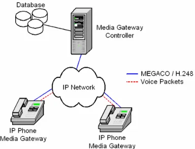
In this paper, we describe the OPNET implementation of MEGACO/H.248 signaling protocol. The OPNET model allows for multi-call and multi-connection scenarios, where any number of Media Gateways (MGs) can simultaneously connect to the Media Gateway Controller (MGC). This design is important for simulations of simultaneous voice conversations. In our simulation scenario, multiple MGs can connect to one MGC via a router. We simulated the call-establishment, call-waiting, and call-release scenarios by employing a complete set of MEGACO/H.248 signaling commands. We also simulated voice transmission using packets encoded with the Real-Time Transport Protocol (RTP).
1. Introduction 1. Introduction 1. Introduction 1. Introduction
Voice over IP (VoIP) technology is currently finding its place in the telecommunication market. It enables a telecommunication company to cut cost by allowing a single network to transmit both data and voice traffic. In addition, VoIP technology is gaining popularity in both commercial and residential markets because the voice quality resulting from packets transmitted over the IP network is comparable to the voice quality resulting from analog signals sent over the Public Switched Telephone Network (PSTN). The MEGACO/H.248 signaling protocol was introduced by the Internet Engineering Task Force (IETF) and International Telecommunication Union (ITU) to help control and manage the increasing volume of VoIP traffic.
With the emergence of VoIP technology, voice traffic is no longer restricted to the circuit-switched network. New IP-based products, such as IP phones and voice cable modems, have been introduced to integrate voice services over the data network. To properly manage and control these voice services, various signaling protocols have been developed. One of these protocols is MEGACO/H.248. It provides the master/slave architecture for controlling VoIP traffic.
The MEGACO/H.248 signaling protocol employs a call control concept. The call control “intelligence” or the master server resides in the Media Gateway Controller (MGC), while the Media Gateway (MG) serves as the slave device (dumb terminal). This concept reduces the complexity of the gateway, making it easier and more suitable for mass deployment.
In this paper, we describe the implementation and simulation of the MEGACO/H.248 protocol using OPNET. All eight MEGACO commands are implemented: Add, AuditCapabilities, AuditValue, Modify, Move, Notify, ServiceChange, and Subtract. The OPNET implementation permits the addition of multiple MGs. This flexibility is important for realistic simulation scenarios where many voice conversations occur
simultaneously. Several MGs are connected to a single MGC via a router. We verified all signaling commands and simulated the MG registration, establishment, waiting, and call-release scenarios. To verify that voice calls were actually established, we generated voice packets encoded using the RTP protocol.
Section 2 describes the history and basic architecture of the MEGACO/H.248 protocol. Sections 3 and 4 describe the design of the MEGACO/H.248 protocol, while Section 5 describes its OPNET implementation. Various call flow simulation scenarios are given in Section 6. Simulation results are presented in Section 7. We conclude with Section 8.
2. MEGACO/H.248 Protocol 2. MEGACO/H.248 Protocol 2. MEGACO/H.248 Protocol 2. MEGACO/H.248 Protocol 2.1. History 2.1. History 2.1. History 2.1. History
In traditional circuit-switched networks, call setups are performed primarily through the backbone of the telephone network. As a result, a proprietary signaling protocol can be used for establishing and deleting connections. However, a well-defined signaling protocol is required for VoIP because VoIP traffic is routed through the public network infrastructure. Various signaling protocols have been designed to control VoIP traffic. Peer-to-peer protocols, such as SIP and H.323, have been introduced. However, for large-scale deployments, these protocols have scalability problems. Hence, a new architecture for signaling protocols was proposed. The control and the media gateway components were re-defined using the master/slave architecture. Figure 1 shows the evolution of the MEGACO/H.248 protocol.
Figure 1: Evolution of the MEGACO/H.248 Protocol [1]. 2.2. Gateway
2.2. Gateway 2.2. Gateway
2.2. Gateway Architecture Architecture Architecture Architecture
The MEGACO/H.248 protocol employs the master/slave architecture, where the MGC acts as a master server, while the MG behaves like a slave device. Figure 2 illustrates the
simplified gateway architecture. In a deployed telecommunication network, one MGC may control multiple MGs.
Figure 2: The Master/Slave Architecture. 2.3. Media Gateway Controller
2.3. Media Gateway Controller 2.3. Media Gateway Controller 2.3. Media Gateway Controller
The MGC is the central point of intelligence for call signaling. It maintains the states of each MG and responds appropriately to any event notification. For instance, upon receiving an off-hook event from an MG, the MGC instructs the MG to play the dial tone and listen for the dual tone multi-frequency (DTMF) tones. 2.4. Media Gateway
2.4. Media Gateway 2.4. Media Gateway 2.4. Media Gateway
The master/slave architecture was designed to eliminate processor-intensive functionalities from the MG. Due to the reduced complexity, the cost of MG is much lower than the cost of MGC, making it more affordable to the commercial and residential markets. Essentially, the MG is a dumb terminal awaiting commands from the MGC for its next actions. Upon the successful creation of a connection, the MG is also responsible for streaming the voice packets over the IP backbone using various encoding/compression algorithms.
2.5. MEGACO/H.248 Command Set 2.5. MEGACO/H.248 Command Set 2.5. MEGACO/H.248 Command Set 2.5. MEGACO/H.248 Command Set
The commands supported by the MEGACO/H.248 protocol are: [MGC ↔ MG]
• ServiceChange – Notify the responder of the new service state
[MGC → MG]
• AuditValue – Determine the characteristics of an endpoint
• AuditCapabilities – Determine the capability of an endpoint • Add – Add a connection
• Modify – Change a connection characteristic • Subtract – Tear down a connection
• Move – Move an endpoint from one connection to another connection (call-waiting)
[MG → MGC]
• Notify – Notify the responder of an event (on-hook)
3. Design Architecture 3. Design Architecture 3. Design Architecture 3. Design Architecture
We have designed two core modules for the MEGACO/H.248 protocol: MGC and MG. 3.1. MGC Architecture 3.1. MGC Architecture 3.1. MGC Architecture 3.1. MGC Architecture
The MGC consists of three main components as shown in Figure 3: Message Receiver (MR), Message Processor (MP), and Message Sender (MS).
Figure 3: MGC Design Architecture [1].
The main responsibility of the Message Receiver is to parse the received messages. The Message Processor is built with the intelligence to handle all eight MEGACO/H.248 commands and to control all MGs in the system. The Message Sender is used to compose and transmit MEGACO messages to MGs.
In our implementation, communications among three components are achieved via local function calls. Upon receiving an event notification message from the MG, the MGC reads the statuses of the related MGs and instructs them with one or more MEGACO/H.248 commands. The responsibilities of each component are summarized in Table 1.
Component Responsibility Message
Receiver
• Receive MEGACO messages from the MGs • Extract parameters from MEGACO
messages
• Redirect message parameters to MP
Message Processor
• Receive message parameters from MR • Read statuses of the related MGs • Determine actions for the related MGs • Request MS to compose response messages
if necessary Message
Sender
• Receive requests from MP • Compose MEGACO messages • Send MEGACO messages to the MGs Table 1: Component Responsibilities in the MGC. 3.2. MG Architecture
3.2. MG Architecture 3.2. MG Architecture 3.2. MG Architecture
3 33 3 (UI), and Voice Generator (VG). Figure 4 illustrates the design architecture of the MG.
The functionalities of the Message Receiver and Message Sender in the MG are similar to those in the MGC. The Message Processor is built to handle any commands sent from the MGC. Upon receiving a command from the MGC, the Message Processor responds accordingly, as listed in Section 2.5.
The User Interface component initiates various events, such as off-hook, flash-hook, and on-hook. Once an event is initiated, the corresponding event notification message is sent to the MGC via the Message Processor and the Message Sender.
Figure 4: MG Design Architecture [1].
The Voice Generator is responsible for generating voice packets upon call establishment. These voice packets are then encapsulated into the RTP payload and sent over the network. Similar to the MGC, communications between MG components are accomplished through local function calls. Table 2 summarizes the responsibilities of each component.
Component Responsibility Message
Receiver
• Receive MEGACO messages from the MGC • Extract parameters from MEGACO messages • Redirect message parameters to the MP Message
Processor
• Receive message parameters from the MR • Respond according to Section 2.5
• Request the MS to compose response messages if necessary
Message Sender
• Receive requests from the MP • Compose MEGACO message
• Send MEGACO messages to the MGC User
Interface
• Receive user request via the object attribute • Request the MS to compose transaction
message Voice
Generator
• Generate voice packets
• Encapsulate voice packet into RTP payloads • Send RTP messages to other MGs
Table 2: Component Responsibilities in the MG.
4. Design Co 4. Design Co 4. Design Co
4. Design Considerationsnsiderationsnsiderations nsiderations 4.1. Unlimited Number of MGs 4.1. Unlimited Number of MGs 4.1. Unlimited Number of MGs 4.1. Unlimited Number of MGs
In order to support the multi-call and multi-connection scenario, the MG architecture needs to support an unlimited number of MGs. Our implementation utilizes a linked-list to keep track of the MGs. This design enables an unlimited number of MG interconnections.
4.2. Control Intelligence in MGC 4.2. Control Intelligence in MGC 4.2. Control Intelligence in MGC 4.2. Control Intelligence in MGC
To illustrate the complexity in the call and multi-connection scenarios, we describe three cases for the Subtract command:
Case 1: MG1 talks with MG2. Then, MG2 hangs up by sending the Notify command to the controller. Since MG1 is not involved in any other connection, the controller sends to both gateways the Subtract commands.
Figure 5: Call Release for the Connection of 2 MGs. Case 2: Initially, MG1 talks with MG2. Then, MG3 calls MG2
and MG2 decides to switch line to talk with MG3. After a while, MG3 hangs up. Since an inactive connection still exists between MG1 and MG2, the controller will send to MG2 a Move command with the SendReceive parameter to activate the connection between MG1 and MG2. At the same time, the Subtract command is sent to MG3.
Figure 6: Call Release for the Connection of 3 MGs. Case 3: First, MG2 talks with MG3. Then, MG1 calls MG2 and
MG4 calls MG3. Both MG2 and MG3 switch line to create connections with the new callers. After a while, MG4 decides to hang up. Since MG2 is still talking with MG1, no active connection exists between MG2 and MG3. As a result, the controller needs to send MG3 a Move command with the ReceiveOnly parameter and the Subtract command to MG4. This case is different from the Case 2 because the controller does not send the Move command with the SendReceive parameter.
Figure 7: Call Release for the Connection of four MGs. 4.3. Object Attributes in MG
4.3. Object Attributes in MG 4.3. Object Attributes in MG 4.3. Object Attributes in MG
In order to support multi-call and multi-connection environment, the MG implementation is based on the object-oriented concept. Each MG stores its own data and contains its own object attributes. With such a design, any number of MGs can be added to the simulation scenario. Figure 8 shows the Object Attributes
dialog box for the configurable data, such as IP address and IP port.
Figure 8: MG Object Attribute Dialog Box. 5. OPNET Implementation
5. OPNET Implementation 5. OPNET Implementation 5. OPNET Implementation
The OPNET node model permits any number of MGs to be registered with the MGC. Therefore, a variety of network topologies can be readily configured. Various network topologies are used in our simulation. The simulation results are given in Section 7.
Three OPNET node models have been implemented: Router Node, MGC Node, and MG Node.
5.1. Router Node 5.1. Router Node 5.1. Router Node 5.1. Router Node
As shown in Figure 9, the router node model consists of eleven transmitters, eleven receivers, and one router processor. The router processor is responsible for routing traffic from a receiver to a transmitter.
Figure 9: Router Node Model.
Figure 10 illustrates the state machine for the router processor, which consists of two states: idle and route_pk. The initial state
of the router processor is the idle state, which waits for the
arrival of packets. Upon receiving packets, the state machine proceeds to the route_pk state. In this state, the router processor
relays packets to the appropriate recipients.
Figure 10: Router Process Model. 5.2. MGC Node
5.2. MGC Node 5.2. MGC Node 5.2. MGC Node
Figure 11 shows the node model of the MGC. The MGC node model consists of a transmitter, a receiver, and the MGC processor. The MGC processor is responsible for parsing MEGACO messages, determining necessary actions for the MGs, and composing the MEGACO messages.
Figure 11: MEGACO MGC Node Model.
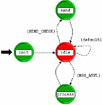
The MGC process model, shown in Figure 12, has four states:
init, idle, send, and process. The init state initializes all the
resources in the MGC. Upon successful initialization, the system proceeds to the idle state, where it either waits for the MGs to
respond or for the MGs to send new MEGACO requests. The system enters to the process state when new MEGACO
messages arrive. In this state, the received messages are parsed and appropriate responses to the MGs are generated. These
5 55 5 responses are placed in an outgoing queue where they are periodically transmitted when the system enters the send state.
Figure 12: MGC Finite State Machine (Process Model). 5.3. MG Node
5.3. MG Node 5.3. MG Node 5.3. MG Node
The MG node, shown in Figure 13, consists of a transmitter, a receiver, and the MG processor. The MG processor is responsible for handling MEGACO/H.248 commands sent from the MGC and detecting events initiated by the user. Furthermore, RTP packets are generated by the MG processor for voice transmission.
Figure 13: MEGACO MG Node Model.
Figure 14 shows the state machine of the MG processor, which consists of the init, idle, msg_pr, mg_pr, and usr_pr states. The
MG objects are initialized in the init state. After the
initialization, the state machine proceeds to the idle state. In this
state, the process waits for the periodic interrupt and packet arrival. When the state machine receives a regular interrupt in the idle state, it enters the usr_pr state. The state machine checks
whether an event was initiated by the user. If an event was initiated, a corresponding event notification message is sent to the MGC. In this state, the state machine also checks for call establishment. Once a call is established, the state machine generates an RTP voice stream to the corresponding MG. Upon receiving a message in the idle state, the state machine proceeds
to the msg_pr state where the packet type is determined. If a
signaling command is received, the state machine moves to the
mg_pr state where the command gets processed. Alternately, if a
RTP packet is received, the state machine moves to the usr_pr
state where the MG object statistics are updated.
Figure 14: MG Finite State Machine (Process Model). 6. Call Flow Scenario
6. Call Flow Scenario 6. Call Flow Scenario 6. Call Flow Scenario
Four basic call flow scenarios were defined to validate the implementation of the eight MEGACO/H.248 commands. These scenarios are MG Registration Procedure, Call Setup Procedure, Call Waiting Procedure, and Call Release Procedure. These scenarios are described in the following subsections, where the MEGACO/H.248 commands and main parameters are included within the sequence diagrams.
6.1. MG Registration Procedure 6.1. MG Registration Procedure 6.1. MG Registration Procedure 6.1. MG Registration Procedure
The first procedure when the MG starts is to register with the MGC using the ServiceChange command (1). This command
enables the MGC to detect and maintain the status of the MG. The MGC then issues the AuditCapability command (3) to
determine what functionalities are available for the MG. The MGC also issues the Modify command (5) to request the
notification of a key-down event or an off-hook event. The sequence diagram for the MG Registration Procedure is shown in Figure 15.
(1)
ServiceChange Request (Method = Restart,Profile = IPPhone/1)
(6) (5) (4) (3) (2) ServiceChange Reply Response to 1 AuditCapability Reply Response to 3 AuditCapability Request (Audit = event, signal, and media)
Modify Request (Event = key/kd) Modify Request Response to 5 MGC MG
6.2. Call Setup Procedure 6.2. Call Setup Procedure 6.2. Call Setup Procedure 6.2. Call Setup Procedure
When a user picks up the phone (MG1), a Notify command (1) is
generated to the MGC. The MGC then requests MG1 to play a dial tone, to listen for the DTMF tones, and to detect the key down (on-hook) event via the Modify command (3). After the
user specifies the remote location, the Notify command (5) with
the destination address is forwarded to MGC. MGC then creates a connection between MG1 and MG2 with two Add commands
(7) (9) and one Modify command (11). When the user at the
remote end picks up the phone (MG2), a Notify command (13) is
generated to the MGC. Finally, MGC sends each phone a Modify
command to establish a media stream between the two gateways. Encapsulated within the Modify command (15) (17) is a request
to stop the ringing signals and to set up the notification mechanism for an on-hook event. The flow diagram for the Call Setup Procedure is shown in Figure 16.
(1) (6) (5) (4) (3) (2) Notify Request (ObservedEvent = key/kd) Notify Reply Response to 1 Modify Request (Event = key/ku and dd/ce,
Signal = cg/dt) Modify Reply Response to 3 Notify Request (ObservedEvent = dd/ce {IP of MG2}) Notify Reply Response to 5 Add Request (Context ID = 1, Termination ID = at/hf, Termination ID = tr, Media LocalControl = RecvOnly,
LocalDescriptor) Add Reply Response to 7 Specific LocalDescriptor (7) (8) Add Request (Context ID = 1, Termination ID = at/hf, Signal = cg/rt, Termination ID = tr, Media LocalControl = SdRecv,
LocalDescriptor, Specific RemoteDescriptor) Add Reply Response to 9 Specific LocalDescriptor (9) (10) (15) (14) (13) (12) (11) (17) (16) Modify Request (Context ID = 1, Termination ID = at/hf, Signal = cg/rt, Termination ID = tr, Specific RemoteDescriptor) Modify Reply Response to 11 Notify Request (ObservedEvent = key/kd) Notify Reply Response to 13 Modify Reply Response to 17 Modify Reply Response to 15 Modify Request (Context ID = 1, Event = key/ku and key/kf,
Signal = {})
Modify Request (Context ID = 1, Event = key/ku and key/kf,
Terminaion ID = at/hf, Signal = {}, Terminaion ID = tr, Media LocalControl = SdRecv)
(18)
MG1 MGC MG2
Figure 16: Call Setup Sequence Diagram. 6.3. Call Waiting Procedure
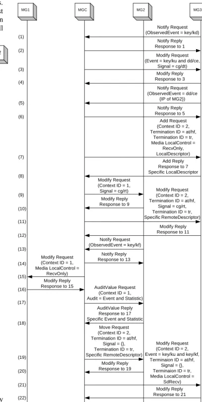
6.3. Call Waiting Procedure 6.3. Call Waiting Procedure 6.3. Call Waiting Procedure
The Call Waiting Procedure is invoked when a third party wishes to call a party that is currently in-session. Following the steps similar to the Call Setup procedure, a receive-only
the party in-session. Upon receipt of the Flash Hook notification (13), the MGC places the current active connection into the inactive mode with the Modify command (15).
Before MG2 switches lines, the MGC reads the statistics of MG2 using the AuditValue command (17). The MGC then sends
to MG2 the Move command (19) to switch the connection to
MG3. Finally, the MGC requests MG3 to stop playing signals and to set up the notification mechanism for an on-hook event via the Modify command (21). The flow diagram for the Call
Waiting Procedure is shown in Figure 17.
(1) (8) (7) (6) (5) (4) (3) (2) Notify Request (ObservedEvent = key/kd) Add Reply Response to 7 Specific LocalDescriptor Add Request (Context ID = 2, Termination ID = at/hf, Termination ID = tr, Media LocalControl = RecvOnly, LocalDescriptor) Notify Reply Response to 5 Notify Request (ObservedEvent = dd/ce {IP of MG2}) Modify Reply Response to 3 Modify Request (Event = key/ku and dd/ce,
Signal = cg/dt) Notify Reply Response to 1 Modify Request (Context ID = 1, Signal = cg/rt) (9) Modify Reply Response to 9 (10) (22) (21) (20) (19) (16) (15) (14) (13) (12) (11) Modify Request (Context ID = 2, Termination ID = at/hf, Signal = cg/rt, Termination ID = tr, SpecificRemoteDescriptor) Modify Reply Response to 11 Notify Request (ObservedEvent = key/kf) Notify Reply Response to 13 Modify Request (Context ID = 1, Media LocalControl = RecvOnly) Modify Reply Response to 15 Move Request (Context ID = 2, Termination ID = at/hf, Signal = {}, Termination ID = tr, Specific RemoteDescriptor) Modify Reply Response to 19 Modify Request (Context ID = 2, Event = key/ku and key/kf,
Terminaion ID = at/hf, Signal = {}, Terminaion ID = tr, Media LocalControl = SdRecv) Modify Reply Response to 21 AuditValue Request (Context ID = 1, Audit = Event and Statistic)
AuditValue Reply Response to 17 Specific Event and Statistic (17)
(18)
MGC MG2 MG3
7 77 7 6.4. Call Release Procedure
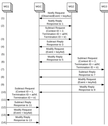
6.4. Call Release Procedure 6.4. Call Release Procedure 6.4. Call Release Procedure
When a user hangs up, a Notify command (1) is sent to the MGC.
The MGC then issues the Subtract command (3) (7) (11), which
tears down the connection with each MG. In preparation for the next call, the MGC sends to each MG a Modify command (5) (9) (13) for
the detection of an off-hook event. The flow diagram for the Call Release Procedure is shown in Figure 18.
Notify Request (ObservedEvent = key/ku) Notify Reply Response to 1 (1) (12) (11) (10) (9) (8) (7) (6) (5) (4) (3) (2) Subtract Request (Context ID = 2, Termination ID = at/hf, Termination ID = tr) Subtract Reply Response to 3 Modify Request (Event = key/kd) Modify Reply
Response to 5 Subtract Request (Context ID = 2, Termination ID = at/hf, Termination ID = tr) Subtract Reply Response to 7 Modify Request (Event = key/kd) Modify Reply Response to 9 Subtract Request (Context ID = 1, Termination ID = at/hf, Termination ID = tr) Subtract Reply Response to 11 Modify Request (Event = key/kd) Modify Reply Response to 13 (14) (13) MG1 MGC MG2 MG3
Figure 18: Call Release Sequence Diagram. 7. Simulation Results
7. Simulation Results 7. Simulation Results 7. Simulation Results
The MEGACO/H.248 OPNET implementation was verified by employing a simple waiting scenario, a complex call-waiting scenario, as well as a multi-call and multi-connection scenario. Section 7.1, 7.2 and 7.3 discuss each scenario.
Due to the large volume of the simulation result, only subset of result in the simple call-waiting scenario is shown.
7.1. Simple Call 7.1. Simple Call 7.1. Simple Call
7.1. Simple Call----Waiting ScenarioWaiting ScenarioWaiting Scenario Waiting Scenario
In the simple call-waiting scenario shown in Figure 19, three MGs are connected to the MGC.
Figure 19: Simple Call-Waiting Topology.
In this simulation scenario, each command was used and the results were verified. The action sequence is:
1. MG1, MG2, and MG3 register with MGC 2. MG1 connects to MG2
3. MG3 calls MG2
4. MG2 switches to MG3, while MG1 is on hold 5. MG3 hangs up, and MG2 switches to MG1 6. MG2 hangs up.
In action sequence 1, the interaction between the MGC and the MGs is:
|---| | [1] MGC received the following message: |---| MEGACO/1 [172.16.0.2]:5555 Transaction = 1000 { Context = - { ServiceChange = ROOT { Service { Method=Restart, ServiceChangeAddress=5555, Profile=IPPhone/1 }}}} |---| | [2] MGC just sent MG (IP: 172.16.0.2) | the following message:
|---| MEGACO/1 [172.16.0.1]:2944 Reply = 1000 { Context = - { ServiceChange = ROOT { Services { ServiceChangeAddress=5555, Profile=IPPhone/1 }}}} |---| | [3] MGC received the following message: |---| MEGACO/1 [172.16.0.3]:5555 Transaction = 2000 { Context = - { ServiceChange = ROOT { Service { Method=Restart, ServiceChangeAddress=5555, Profile=IPPhone/1 }}}} |---| | [4] MGC just sent MG (IP: 172.16.0.3) | the following message:
|---| MEGACO/1 [172.16.0.1]:2944 Reply = 2000 { Context = - { ServiceChange = ROOT { Services { ServiceChangeAddress=5555, Profile=IPPhone/1 }}}}
|---| | [5] MGC just sent MG (IP: 172.16.0.2) | the following message:
|---| MEGACO/1 [172.16.0.1]:2944 Transaction = 1 { Context = - { AuditCapabilities = ui { Audit{Events, Signals} }}} |---| | [6] MGC received the following message: |---| MEGACO/1 [172.16.0.4]:5555 Transaction = 3000 { Context = - { ServiceChange = ROOT { Service { Method=Restart, ServiceChangeAddress=5555, Profile=IPPhone/1 }}}} |---| | [7] MGC just sent MG (IP: 172.16.0.4) | the following message:
|---| MEGACO/1 [172.16.0.1]:2944 Reply = 3000 { Context = - { ServiceChange = ROOT { Services { ServiceChangeAddress=5555, Profile=IPPhone/1 }}}} |---| | [8] MGC received the following message: |---| MEGACO/1 [172.16.0.2]:5555 Reply = 1 { Context = - { AuditCapabilities = ui { Event {key/kd,key/ku,key/kf,dd/ce}, Signal {cg/dt,cg/rt} }}} |---| | [9] MGC just sent MG (IP: 172.16.0.2) | the following message:
|---| MEGACO/1 [172.16.0.1]:2944 Transaction = 2 { Context = - { Modify = ui { Events = 1 {key/kd} }}} |---| | [10] MGC received the following message: |---| MEGACO/1 [172.16.0.2]:5555 Reply = 2 { Context = - { Modify = ui |---| | [11] MGC just sent MG (IP: 172.16.0.3) | the following message:
|---| MEGACO/1 [172.16.0.1]:2944 Transaction = 3 { Context = - { AuditCapabilities = ui { Audit{Events, Signals} }}} |---| | [12] MGC received the following message: |---| MEGACO/1 [172.16.0.3]:5555 Reply = 3 { Context = - { AuditCapabilities = ui { Event {key/kd,key/ku,key/kf,dd/ce}, Signal {cg/dt,cg/rt} }}} |---| | [13] MGC just sent MG (IP: 172.16.0.3) | the following message:
|---| MEGACO/1 [172.16.0.1]:2944 Transaction = 4 { Context = - { Modify = ui { Events = 2 {key/kd} }}} |---| | [14] MGC received the following message: |---| MEGACO/1 [172.16.0.3]:5555 Reply = 4 { Context = - { Modify = ui }} |---| | [15] MGC just sent MG (IP: 172.16.0.4) | the following message:
|---| MEGACO/1 [172.16.0.1]:2944 Transaction = 5 { Context = - { AuditCapabilities = ui { Audit{Events, Signals} }}} |---| | [16] MGC received the following message: |---| MEGACO/1 [172.16.0.4]:5555 Reply = 5 { Context = - { AuditCapabilities = ui { Event {key/kd,key/ku,key/kf,dd/ce}, Signal {cg/dt,cg/rt} }}}
9 99 9
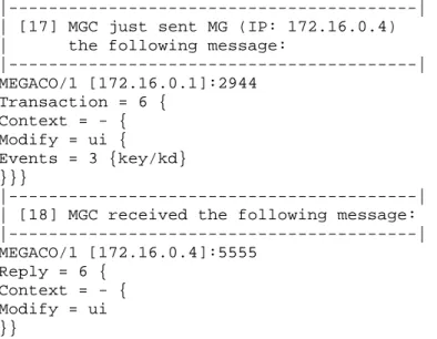
|---| | [17] MGC just sent MG (IP: 172.16.0.4) | the following message:
|---| MEGACO/1 [172.16.0.1]:2944 Transaction = 6 { Context = - { Modify = ui { Events = 3 {key/kd} }}} |---| | [18] MGC received the following message: |---| MEGACO/1 [172.16.0.4]:5555 Reply = 6 { Context = - { Modify = ui }} 7.2. Complex Call 7.2. Complex Call 7.2. Complex Call
7.2. Complex Call----Waiting ScenarioWaiting ScenarioWaiting Scenario Waiting Scenario
In the complex call-waiting scenario, four MGs are connected to the MGC. The network topology of this simulation scenario is shown in Figure 20. The action sequence is:
1. All MGs register with MGC 2. MG2 connects to MG3
3. MG1 calls MG2, and MG4 calls MG3
4. MG2 switches to MG1, while MG3 switches to MG4 5. MG2 and MG3 switches back, while MG1 and MG4 are put
on hold 6. MG3 hangs up
7. MG4 gets removed from the inactive connection 8. MG2 switches back to MG1
9. MG2 hangs up.
Figure 20: Complex Call-Waiting Topology. 7.3. Multi
7.3. Multi 7.3. Multi
7.3. Multi----Call and MultiCall and MultiCall and MultiCall and Multi----Connection ScenarioConnection ScenarioConnection ScenarioConnection Scenario
This simulation scenario is used to verify the OPNET implementation in a multi-call and multi-connection environment. Five MGs are connected to the MGC. The network topology is shown in Figure 21. The action sequence is:
1. All MGs register with MGC
2. MG1 connects to MG2, while MG4 connects to MG5 3. MG3 calls MG2
4. MG2 switches to MG3, while MG1 is put on hold 5. MG3 hangs up, and MG2 switches back to MG1 6. MG2 and MG4 hang up.
Figure 21: Multi-Call and Multi-Connection Topology. 8. Conclusion and Future Work
8. Conclusion and Future Work 8. Conclusion and Future Work 8. Conclusion and Future Work
In this paper, we describe the OPNET implementation of the MEGACO/H.248 signaling protocol between the MGC and MG. We provide an overview of the MEGACO/H.248 signaling components and the commands. The OPNET implementation of the MEGACO/H.248 protocol supports an unlimited number of MG interconnections. We successfully implemented all MEGACO/H.248 commands. Several call scenarios between the MGC and MGs were simulated, which validated our implementation. Future development of this project would be implementation of the MEGACO/H.248 protocol over the IP network.
9. References 9. References 9. References 9. References
[1] S. Wu, M. Riyadh, and R. Mannan, and Lj. Trajković, “OPNET implementation of the Megaco/H.248 protocol,” OPNETWORK 2002, Washington, DC, Aug. 2002.
[2] T. Taylor, “Megaco/H.248: a new standard for media gateway control,” IEEE Communications Magazine, pp.
124-132, October 2000.
[3] “Media Gateway Control (Megaco),” Alcatel Executive Briefing, Alcatel Internetworking, December 2001.
[4] N. Greene, M. Ramalho, and B. Rosen, “Media Gateway Control Protocol architecture and requirements,” RFC 2805, April 1999: http://www.ietf.org/rfc/rfc2805.txt (accessed in February 2003).
[5] F. Cuervo, N. Greene, A. Rayhan, C. Huitema, B. Rosen, and J. Segers, “Megaco protocol version 1.0,” RFC 3015, November 2000: http://www.ietf.org/rfc/rfc3015.txt (accessed in February 2003).
[6] P. Blatherwick, R. Bell, and P. Holland, “Megaco IP phone media gateway application profile,” RFC 3054, January 2001: http://www.ietf.org/rfc/rfc3054.txt (accessed in February 2003).
[7] M. Brahmanapally, P. Viswanadham, and K. Gundamaraj, “Megaco/H.248 call flow examples,” October 2002:
http://www.ietf.org/internet-drafts/draft-ietf-megaco-callflows-01.txt (accessed in February 2003).
[8] H. Schulzrinne, S. Casner, R. Frederick, and V. Jacobson, “RTP: a transport protocol for real-time applications,” RFC 1889, January 1996: http://www.ietf.org/rfc/rfc1889.txt (accessed in August 2002).
![Figure 1: Evolution of the MEGACO/H.248 Protocol [1].](https://thumb-us.123doks.com/thumbv2/123dok_us/8708021.2357236/1.918.475.867.775.982/figure-evolution-megaco-h-protocol.webp)
![Figure 4: MG Design Architecture [1].](https://thumb-us.123doks.com/thumbv2/123dok_us/8708021.2357236/3.918.61.438.299.547/figure-mg-design-architecture.webp)