Extreme Networks, Inc. 3585 Monroe Street Santa Clara, California 95051 (888) 257-3000
Network Infrastructure
Manager User Guide
Infrastructure Client for ISM Provision
©2002 Extreme Networks, Inc. All rights reserved. Extreme Networks and BlackDiamond are registered trademarks of Extreme Networks, Inc. in the United States and certain other jurisdictions. ExtremeWare, ExtremeWare Vista, ExtremeWorks, ExtremeAssist, ExtremeAssist1, ExtremeAssist2, PartnerAssist, Extreme Standby Router Protocol, ESRP, SmartTraps, Alpine, Summit, Summit1, Summit4, Summit4/FX, Summit7i, Summit24, Summit48, Summit Virtual Chassis, SummitLink, SummitGbX, SummitRPS, and the Extreme Networks logo are trademarks of Extreme Networks, Inc., which may be registered or pending registration in certain jurisdictions. The Extreme Turbodrive logo is a service mark of Extreme Networks, which may be registered or pending registration in certain jurisdictions. Specifications are subject to change without notice.
Contents
Preface
Introduction ix
Terminology x
Conventions x
Related Publications xii
1
Infrastructure and Services Management Provision
Overview
Overview 1-1
Summary of Features 1-2
How ISM Provision works 1-3
Your Network Devices 1-4
ISM Provision Server 1-4
Device Communicators 1-4
Network Infrastructure Manager Client 1-5
IP Service Manager Client 1-5
2
Starting Network Infrastructure Manager
Overview 2-1
Network Infrastructure Manager Overview 3-1
Summary of Features 3-1
NIM Views 3-2
Selecting NIM Views 3-2
Network Provision View 3-5
Network Inventory View 3-6
Providers Administration View 3-7
Server Administration View 3-8
Change Control View 3-9
NIM Icons 3-9
Open Changes 3-10
Save Changes 3-10
Modify Object 3-10
Copy 3-10
Paste 3-10
Delete 3-10
Move Device 3-11
Verify Configuration 3-11
Synchronize 3-11
Commit Changes 3-11
Revert Changes 3-11
Help 3-11
4
Network Provisioning
Overview 4-1
Network Provision View Panels 4-3
Network Panel 4-4
Templates Panel 4-5
Verification Panel 4-5
Properties Panel 4-5
Configuration Objects 4-5
Key Information 4-6
Unsupported Configuration Commands 4-6
View Multiple Configuration Objects 4-15
Modify Visible Configuration Options 4-18
Modify View Options 4-20
Create and Modify Network Device Configurations 4-20
Add a New Device 4-21
Add a Configuration Object 4-22
Modify a Configuration Object 4-26
Copy a Device or other Object 4-29
Save Changes Without Changing Network Configuration 4-34
Remove Changes (Revert to Server State) 4-34
Change an Unmanaged Device into a Managed Device 4-35
Access Extreme Devices Directly 4-39
Use Telnet to access a device 4-39
Use Extreme WebVista to access a device 4-40
5
Managing the Network Inventory
Overview 5-1
Manage the Network Inventory List 5-2
Add a Device to the Network Inventory 5-2
Modify a Network Inventory Device Listing 5-10 Delete a Device from the Network Inventory 5-11
Import Inventory File 5-11
Export Inventory File 5-15
Manage the Network Inventory Devices 5-16
Upload Devices 5-16
Save Running Configurations 5-18
6
Managing Providers
Overview 6-1
The Infrastructure Provider 6-2
Device Access 6-2
7
Managing the ISM Provision Server
Overview 7-1
Communicators Tab 7-2
Logs Tab 7-3
Control Tab 7-4
Manage Device Communicators 7-4
Add a Device Communicator 7-5
Modify a Device Communicator 7-5
Delete a Device Communicator 7-6
View Device Communicator Logs 7-7
Manage ISM Provision Server 7-8
View Other Connected Users 7-8
Send Broadcast Message 7-9
Stop Server 7-10
View Server Log 7-11
8
Change Control
Overview 8-1
Jobs 8-2
Configuration Versions 8-2
Change Control Tasks 8-3
View Current Job Changes 8-3
View Committed, Scheduled, or Saved Jobs 8-4
Delete Scheduled or Saved Jobs 8-7
Create Configuration Version 8-7
Rollback to a Configuration Version 8-9
8-10
A
ISM Provision Devices, Images, and Modules
C
ISM Provision Server Maintenance
Overview C-1
Database Backup Utility C-1
Database Backup Utility Location C-2
Using the Database Backup Utility C-2
Installing a Backup Database C-3
Adding a License Key C-3
Preface
This Preface provides an overview of this guide, describes guide conventions, and lists other publications that may be useful.
Introduction
This guide provides the required information to manage a network using Extreme Networks’ Network Infrastructure Manager (NIM) client as the interface for Extreme Networks’ Infrastructure and Services Management Provision (ISM Provision). This guide is intended for use by network administrators who are responsible for configuring network equipment. It assumes a basic working knowledge of: • Local area networks (LANs).
• Ethernet concepts.
• Ethernet switching and bridging concepts. • Routing concepts.
• Internet Protocol (IP) concepts.
• Routing Information Protocol (RIP) and Open Shortest Path First (OSPF). • Simple Network Management Protocol (SNMP).
Additionally, this guide assumes a familiarity with the features and functionality of ExtremeWare Software and with Extreme Networks’ hardware. See the section, “Related Publications”, for documents covering Extreme Networks’ Software and Hardware.
If the information in the release notes shipped with your software differs from the information in this guide, follow the release notes.
Terminology
When features, functionality, or operation is specific to the Summit, Alpine, or
BlackDiamond switch family, the family name is used. Explanations about features and operations that are the same across all Extreme switch product families simply refer to the product as the “Extreme device” or “Extreme switch.” Explanations about features that are the same for all devices managed by Network Infrastructure Manager (both Extreme devices and others) simply refer to “devices.”
Conventions
Table 1 and Table 2 list conventions that are used throughout this guide. Table 1: Notice Icons
Icon Notice Type Alerts you to...
Note Important features or instructions.
Caution Risk of personal injury, system damage, or loss of data.
Warning Risk of severe personal injury.
Table 2: Text Conventions
Convention Description
Screen displays This typeface indicates command syntax, or represents information as it appears on the screen.
Screen displays bold
Conventions
The words “enter” and “type”
When you see the word “enter” in this guide, you must type
something, and then press the Return or Enter key. Do not press the Return or Enter key when an instruction simply says “type.”
[Key] names Key names are written with brackets, such as [Return] or [Esc]. If you must press two or more keys simultaneously, the key names are linked with a plus sign (+). Example:
Press [Ctrl]+[Alt]+[Del].
Words in Bold type GUI elements are written in bold type. Example: menu items, buttons, field names
Words in italicized type Italics emphasize a point or denote new terms at the place where they are defined in the text. Italics are also used to denote variables, such as VLAN names, or user account names.
Table 2: Text Conventions (continued)
Related Publications
The publications related to this one are: • ISM Provision Installation Guide
• IP Service Manager User Guide
• ExtremeWare Software User Guide
Documentation for Extreme Networks products is available on the World Wide Web at the following location:
1
Infrastructure and Services
Management Provision Overview
Overview
Extreme Networks’ Infrastructure and Services Management Provision (ISM Provision) is a tightly connected collection of components for delivering services to customers and for managing your network. ISM Provision allows you to easily extend services to your network users by defining and provisioning bundles of IP services. Services are
managed as simple objects that are easy to apply to customers, but the configuration changes required to support the delivery of services is managed by ISM Provision. ISM Provision also allows you to control all or a portion of your network, by controlling the configurations of the devices in the network.
ISM Provision is designed to make it much easier to roll out changes to the network. You can add devices and make configuration changes offline and apply them to your network later. Planned changes are verified against a comprehensive set of rules to assure that the changes can be applied to your network and will not conflict with existing configurations. Incomplete sessions can be saved to be completed later.
Services provided across a group of customers can be easily modified. Once a service is updated, the change is applied to all customers using the service. ISM Provision manages all the configuration changes to make the modifications.
Network Infrastructure Manager (NIM) is the GUI client portion of ISM Provision that controls and manages the infrastructure of your network, the configurations of your network devices. NIM works closely with IP Service Manager (IPSM), the GUI client portion of ISM Provision that allows a provider to manage customers, service bundles, and policy based services.
Infrastructure and Services Management Provision Overview
Summary of Features
• Version Control of Network Configuration • Staging of Network Configuration Changes • Configuration rules checking
• Helps Manage the VLANs, Access Lists, and QoS Profiles Required to Support Subscribers
• Provides Service-Level Abstractions to Manage Subscribers
• Client/Server Java architecture - platform independent and scalable • Offline and on-line tool - used in both green field and existing network
environments
• Co-exists with other management tools using CLI or SNMP
• Version control for configurations and deployment module for system rollouts • Provides an abstraction model that simplifies and automates both infrastructure and
subscriber provisioning life-cycles
How ISM Provision works
How ISM Provision works
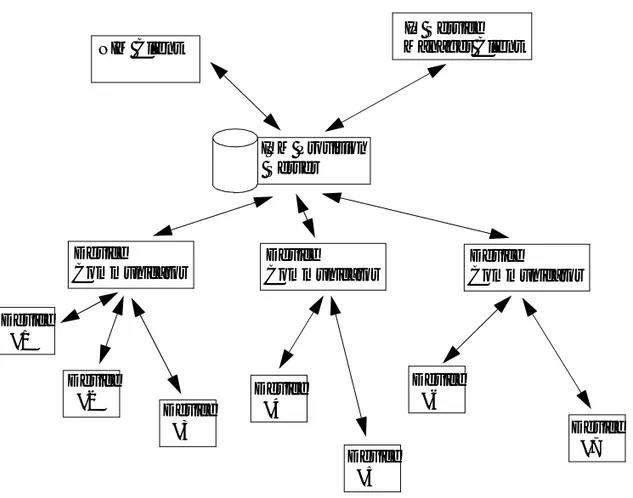
Figure 1-1: ISM Provision Components
ISM Provision consists of several different components: • ISM Provision Server
• Device Communicators
• Network Infrastructure Manager Client • IP Service Manager Client
These components work together to manage another important component:
ISM Provision Server NIM Client IP Service Manager Client Device Communicator Device Communicator Device Communicator Device #1 Device #2 Device #3 Device #4 Device #5 Device #6 Device #7
Infrastructure and Services Management Provision Overview
• Your Network Devices
The following sections describe these components and how they interact in more detail.
Your Network Devices
The network managed by ISM Provision consists of your current existing network of Extreme Network devices, or a subset of your devices. Many devices can be managed by ISM Provision simultaneously. The devices are managed by querying them for their configurations, and by sending new configuration commands to them. Once ISM Provision manages a device, it will periodically check that the device configuration for changes.
ISM Provision Server
The ISM Provision server is the heart of ISM Provision. You may have more than one instance of the other components, but only one server. The server contains the information about the configurations of the managed devices, configurations that are scheduled to be applied to the network at a later time, and previous configurations. An ISM Provision server can contain the configurations of a large number of devices, but does not communicate with the devices directly. Instead, it uses device communicators to handle this task.
The ISM Provision server also contains the saved configuration changes that have not yet been applied to the network. These changes may be saved to edit later, or may be applied at a future time to the network.
Device Communicators
The device communicators control the communication between the network devices and the ISM Provision server. All queries to devices from the ISM Provision server and all commands from the ISM Provision server to the devices are handled by the device communicators. To spread the processing load across hosts, there can be more than one device communicator in an ISM Provision installation, but only one per host.
For example, in a network of 100 devices all managed with the same ISM Provision server, you might have five different device communicators, each talking with twenty devices. Any one managed device can only be managed by one device communicator, otherwise conflicts will occur.
How ISM Provision works
Typically, you will install one device communicator on the same host as the ISM Provision server, and then add other device communicators on other hosts as needed to manage the processing load of communicating with your devices.
Network Infrastructure Manager Client
The Network Infrastructure Manager (NIM) client is used to manage changes to the network infrastructure. With NIM you can prepare and commit changes to the current network configuration, and add new devices to be provisioned. Before changes are rolled out to your network, NIM tests your proposed changes against a set of rules designed to spot and help you correct errors (for example, duplicate IP addresses assigned to different VLANs).
The NIM client also manages the providers, provider accounts, and provider access to network resources. With NIM you can define a provider and restrict that provider’s control to a specific set of ports on a specific set of devices. You can also restrict the allowable VLAN IDs and IP addresses that the provider can assign.
The NIM client also manages the ISM Provision server and device communicators. You can see the status of the server and communicators and examine their logs. You can also see who is currently connected to the ISM Provision server and send a broadcast message to them. You can shutdown the ISM Provision server from within NIM. Finally, you can review the current changes in your session, review committed, saved and scheduled jobs, and perform configuration versioning.
IP Service Manager Client
The IP Service Manager client allows providers to manage subscribers (subscribers consist of a VLAN and a single port in your network). IP Service Manager also allows you to configure service bundles (these correspond to QoS profiles) and policy based services (these correspond to access control lists) for these subscribers.
2
Starting Network Infrastructure
Manager
Overview
Since the Network Infrastructure Manager (NIM) client is part of ISM Provision, NIM relies on a running ISM Provision server and device communicator. This chapter assumes that you already have a functioning ISM Provision server and device communicator. For information about installing and starting an ISM Provision server and device communicator, see the document, ISM Provision Installation Guide, available as a PDF file, “install-1-0.pdf”on your ISM Provision CDROM.
Starting Network Infrastructure Manager
The following is a short summary of the steps to start Network Infrastructure Manager Summary Steps. To start Network Infrastructure Manager you must:
1 Launch the NIM Client
2 Specify the ISM Provision Server 3 Enter a User Account Name
4 Enter the Password for the Account
Detailed Steps. The following steps are a more detailed explanation of the previous section.
Starting Network Infrastructure Manager
1 Launch the NIM Client
Launch the NIM client as you would launch other applications on your host. For example, Windows users can select Network Infrastructure Manager from the Start>Programs>Extreme Networks>ISM Provision>Applications menu. Solaris users can launch the nim executable file from the /opt/extreme/ismprov/bin
directory by using a graphical file manager application to double-click on its icon, or by typing:
/opt/extreme/ismprov/bin/nim
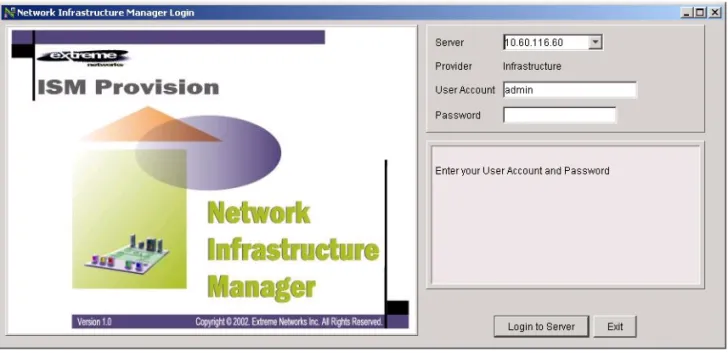
Once the application starts, you will see the login screen similar to the one shown in Figure 2-1.
Figure 2-1: Network Infrastructure Manager Login Screen 2 Specify the ISM Provision Server
Once the login screen appears, you will specify the ISM Provision server. Specify the IP address of the server or the hostname by typing it into the server field. Figure 2-2 shows the login screen and server field in more detail (if the server is on the same host as the NIM client, you can also specify “localhost”).
NIM will store the IP addresses and names that you have specified in previous sessions, so you may find your server already specified, or you may be able to select
Overview
it from the drop-down list in the server field. Click on the down-arrow on the right side of the field and select the server.
Figure 2-2: NIM Login Screen Detail 3 Enter a User Account Name
Starting Network Infrastructure Manager
In the User Account field, enter your user account name. The previously accessed account name is displayed in the field, so you may not need to enter a name. 4 Enter the Password for the Account
Enter the account password. The account passwords are not saved and will need to be entered every session.
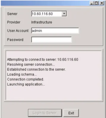
Once the information has been entered, click the Login to Server button, then the NIM client will attempt to connect with the ISM Provision server. While it is connecting you will see messages similar to those in Figure 2-3.
Figure 2-3: The NIM Client Connecting to the ISM Provision Server
Overview
Figure 2-4: NIM Initial Screen
When NIM launches, the Network Provision view is initially displayed. You are now ready to use NIM. See Chapter 3, Network Infrastructure Manager Overview, for more information about NIM.
3
Network Infrastructure Manager
Overview
Network Infrastructure Manager Overview
Network Infrastructure Manager (NIM) is composed of a number of views that are organized to complement your workflow. The different views allow you to manage different functional areas controlled by NIM. They are:
• Network Provision View • Network Inventory View • Providers Administration View • Server Administration View • Change Control View
NIM also has a number of icons and menus that are available from all of the views.
Summary of Features
• Layer 1 to 4 configuration: ports, trunks, VLANs, IP addressing, routing protocols, ACLs
• Extreme Networks-only device support: BlackDiamond, Alpine, and Summit (i chipset and 24e3 only)
• Service Provider Administration (wholesale model support)
• ISM Provision Server Administration (device communicators, utilities) • Configuration Versioning (change histories, checkpoints)
Network Infrastructure Manager Overview
• Configuration and topology import from devices and input files
NIM Views
When NIM is first launched you will be presented with the Network Provision view, as shown in Figure 3-1. The different views are described below.
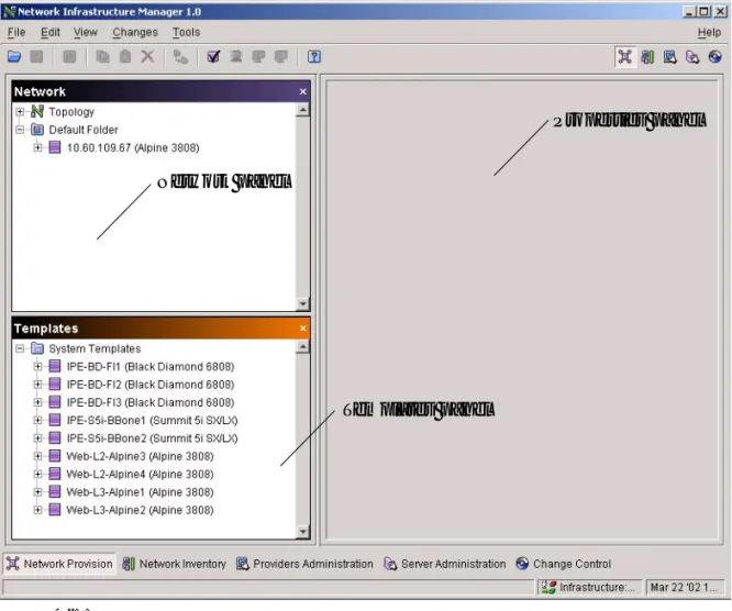
Figure 3-1: Initial NIM Network Provision View
Selecting NIM Views
There are four ways to select a particular view. One way is to select the desired view from the icons near the upper right side of the NIM client screen, as shown in
Network Infrastructure Manager Overview
Inventory, Providers Administration, Server Administration, and Change Control. Select the icon to display the view.
Figure 3-2: Selecting a NIM View Using Icons
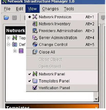
A second way is to select the View menu and choose the view, as shown in Figure 3-3. A third way is to use the shortcut keys also shown in Figure 3-3. Press the [ALT] key
Network Provision
Network Inventory
Providers Administration Server Administration
Network Infrastructure Manager Overview
and a number key at the same time to use the shortcuts. For example, press [ALT]+3 to choose the Providers Administration view.
Figure 3-3: Selecting a NIM View Using the Menu
A fourth way is to select the view from the named icons near the bottom of the NIM client screen, just above the status line, as shown in Figure 3-4.
Network Infrastructure Manager Overview
Network Provision View
Figure 3-5: NIM Network Provision View
The Network Provision view is used to stage changes to your network before actually committing them to your devices. From this view, you build configurations for new devices, modify configurations for existing devices, and view the current configurations of existing devices. Once you have made changes, you will either commit the changes to the network, save the changes without affecting the network, or throw away the changes by reverting to the current server state.
Saved changes are not saved on the local client host, but on the ISM Provision server, so they are accessible from other NIM clients, and can be viewed and reviewed by other NIM users. Saved changes can also be scheduled to be committed to your network at a later time.
Committed changes are also saved on the ISM Provision server, but they are also pushed out to your network devices. Committed changes become part of the current configurations of your devices.
Network Infrastructure Manager Overview
At any time you may test your modified configurations against a number of rules derived from Extreme Network devices, ExtremeWare, and good networking practices. For example, if you attempt to re-issue an IP address that would conflict with your current configurations, you will be warned and the error will be identified so you can take action. You will also be warned if you select an incompatible set of modules for an Extreme Networks chassis.
Network Inventory View
Figure 3-6: Network Inventory View
The Network Inventory view shows you the managed devices in your network. Managed devices are specified by their network name or IP address. ISM Provision manages the devices through the administrator account of each device. From this view you can add and remove managed devices, select which device communicator talks to each of the managed network devices, upload device configurations to the server, save device configurations to the device’s NVRAM, and view the current status of the device.
If you have an existing network, this is likely the first view you will use. To capture the current state of your network you will add your devices to the inventory. By adding
Network Infrastructure Manager Overview
your devices to the inventory, ISM Provision will read the current configurations and store them in the ISM Provision server.
From this view you can also export and import inventory files (you can also do this from the File menu). These files contain the administrator access information for devices. If you plan to add a large number of devices to the network inventory, you will likely create an inventory file and import it.
Providers Administration View
Figure 3-7: Providers Administration View
The Providers Administration view manages the providers, the provider user accounts and passwords, and provider resources that are accessible from the other ISM Provision client, IP Service Manager. From this view you can add, modify, and delete provider user accounts and passwords for IP Service Manager, and you can control provider access to devices, device ports, VLAN IDs, and IP addresses.
The Providers Administration view also manages the login accounts for NIM itself. In this view you can change passwords and add and delete accounts. The special provider name “Infrastructure” represents all of the user accounts for NIM. (That is why the NIM login screen has a read-only entry of “Infrastructure” for the Provider field.)
Network Infrastructure Manager Overview
From this view there is a conversion tool to help you setup existing NIM objects to use in the IP Service Manager client.
Server Administration View
Figure 3-8: Server Administration View
The Server Administration view allows you to manage the ISM Provision server and device communicator servers. From this view you can add, modify, and delete device communicators, and verify their status. You can examine who is connected to the ISM Provision server, send a broadcast message to all connected users, and shut down the ISM Provision server. You can also examine the device communicator and ISM Provision server logs.
Network Infrastructure Manager Overview
Change Control View
Figure 3-9: Change Control View
From the Change Control view you can manage the changes you create with NIM. For your current session, you can see the changes that you have made and not yet saved or committed to the network. There is a record of changes committed to the network and changes scheduled to be committed to the network.
You can also create network configuration versions; a collection of configurations for your entire managed network. This allows you to rollback all your device
configurations to a known state.
NIM Icons
There are a number of icons visible from all of the NIM views. When the function associated with an icon is available, the icon is in color. When the icon function is not available, the icon is greyed out.
Network Infrastructure Manager Overview
Figure 3-10: NIM Icons: Open Changes, Save Changes, Modify Object, Copy, Paste,
Delete, Move Device, Verify Configuration, Synchronize, Commit Changes, Revert Changes, Help
Open Changes
Select this icon to open changes that you have previously saved to the ISM Provision server. The changes will be incorporated into your Network
Provision view. Once opened, you can further modify the Network Provision view, or commit the changes to the network.
Save Changes
Select this icon to save changes that you have made. Saved changes are not pushed out to the network devices, but are saved on the ISM Provision server for further work, or to be viewed by others.
Modify Object
Select this icon to modify the currently selected object. In general, an object-specific wizard will open to allow you to change the object properties.
Copy
Select this icon to copy the currently selected object.
Paste
Select this icon to paste the previously copied object.
Delete
Network Infrastructure Manager Overview
Move Device
Select this icon to move the currently selected device from one folder to another.
Verify Configuration
Select this icon to check your changes against the ISM Provision rules. If errors or warnings are found, they will be identified, and you can change them.
Synchronize
Select this icon to merge the changes from the server into your view, if you did not update your view when you were first notified.
When the network configuration changes because of the actions of another user, the state of the ISM Provision server changes. Your current view is now out of sync with the server. When the ISM Provision server changes, it notifies the NIM client and displays the Server Update Notification dialog box (if this option is set). From this box you can either select Update Now or Update Later. By selecting Update Now, the server changes are merged into your view. If you select Update Later, the Synchronize icon becomes available. At a later time you can then select the icon, and merge the sever changes into your view.
Commit Changes
Select this icon to commit your changes to ISM Provision. The changes are incorporated into the ISM Provision server and the device configurations are changed.
Revert Changes
Select this icon to discard changes you have made in NIM. Your changes will be removed and your view will be refreshed from the server.
Help
4
Network Provisioning
Overview
From the Network Provision view of Network Infrastructure Manager you can display and modify device configurations. These configurations may represent the actual configurations on your network, modified configurations that you intend to deploy to your network, or configurations for devices that do not currently exist in your network. You can copy the configuration of an existing device and modify it, and you can save typical configurations that you use in your network as a template to aid in adding additional devices.
At any time during the process of modifying the network configurations in Network Provision view, you may save your work without affecting the current network, to continue modifying later, or to allow others to review the changes before they are implemented. You can also back out the changes by reverting to the server state, so the Network Provision view only shows what is currently committed to the server.
Once you have modified the configurations in the view, you can apply the changes nearly simultaneously to the devices in your network by committing the changes to the ISM Provision server. Before changes are committed, or at any time you choose during the editing process, the changes are checked against a set of rules to detect errors like duplicate IP addresses, or unsupported module combinations.
This chapter explains the following concepts about the Network Provision view of Network Infrastructure Manager:
Network Provisioning
• Configuration Objects • Key Information
• Unsupported Configuration Commands • Managed and Unmanaged Devices
This chapter also explains how to perform a number of tasks in the Network Provision view. The first set of tasks primarily deal with displaying the configurations in the system. The following tasks are documented in this first section:
• View Device Configurations
— View a Single Configuration Object — View Multiple Configuration Objects — Modify Visible Configuration Options — Modify View Options
The next set of tasks deal with adding and modifying configuration objects. Here you would find information about adding a new device configuration or creating a new configuration object. The following tasks are documented in the section:
• Create and Modify Network Device Configurations — Add a New Device
— Add a Configuration Object — Modify a Configuration Object — Copy a Device or other Object
— Save Changes Without Changing Network Configuration — Remove Changes (Revert to Server State)
— Change an Unmanaged Device into a Managed Device
The last set of tasks explains how to directly access a device in your network to manually modify its configuration. Since ISM Provision cannot directly support some commands, you may need to set some commands manually, either from the command line or from the web interface. The following tasks are documented in the section: • Access Extreme Devices Directly
— Use Telnet to access a device
Network Provision View Panels
Network Provision View Panels
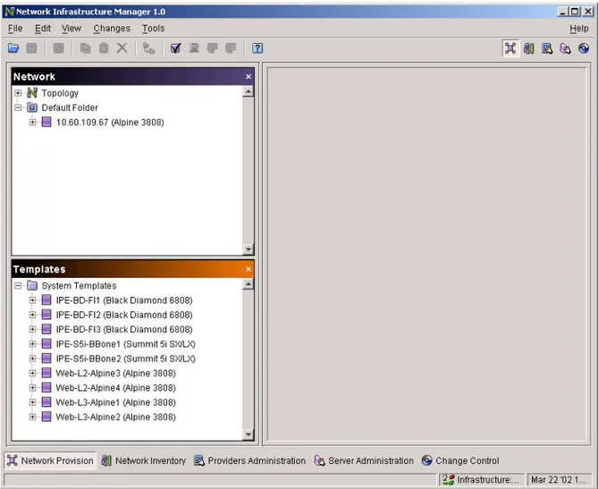
When you select the Network Provision view of NIM you will see a screen similar to that in Figure 4-1. This figure shows a single device in the default device folder,
10.60.109.67 (Alpine 3808). To create this example, an existing network device was added
to the Network Inventory, as described in Chapter 5, “Managing the Network
Inventory”. If you have not already added an existing device you can display a device configuration by adding a new device or copying a template to the Network panel in the Network Provision view. See the section, “Add a New Device”, or the section, “Copy a Device or other Object”, for instructions.
Figure 4-1: Network Provision View with One Device
Properties panel
Templates panel Network panel
Network Provisioning
The Network Provision view can show three named panels: Network, Templates, and Verification (The Verification panel is not visible in Figure 4-1). Additionally, there is a forth, unnamed panel that is always visible in Network Provision view. For
convenience, this document will refer to that panel as the Properties panel. Initially, NIM will show the Network, Templates, and Properties panel, and will show the Verification panel when a verification is performed. You can show the panels at any time from the View menu (see Figure 4-2).
Figure 4-2: Selecting Network Provision Panels
To show a panel, select the View menu item for that panel. If the panel is visible, selecting its View menu item will close the panel.
Network Panel
The Network panel displays the configurations of any network devices that are in the network inventory (existing devices), any unmanaged device that you have created, and any configuration changes that you have made. Any object in the Network panel that has a plus (+) sign next to it can be expanded by clicking it. For example, if you click on
Configuration Objects
the plus sign next to a device name, the objects that make up that device will be displayed, like modules and VLANs. You can further expand any object displayed with the plus sign.
Templates Panel
The Templates panel displays device templates that were part of the initial installation and any that you have added. Like the Network panel, you can expand the objects in the Templates panel by clicking on the plus sign. You can also modify the templates in the Templates panel as you do the devices in the Network panel.
You can copy and paste a device from the Network panel into the Templates panel to be used as a template for later devices. Choose a device that has a typical configuration and use it for a template for adding similar devices. When ready to add a new device, copy and paste from the Templates panel to the Network panel, and modify its parameters.
Verification Panel
The Verification panel displays the results of verifying your device configurations against the ISM Provision rule set. From here you are alerted to any warnings or errors, and given an opportunity to correct them. You will also find suggested corrections for the error and warnings issued by ISM Provision. When you select an error or warning, the object causing the message is highlighted in the Network panel. You can then select and modify the object to correct the problem.
Properties Panel
The Properties panel shows information about the object selected in the Network panel. When you expand the objects in the Network panel you can display finer levels of detail about the configuration of your devices.
Configuration Objects
The Network Provision view displays the configuration objects that make up your network. Objects are an abstraction, a way to think about groups of commands that make up the configurations in your network. Here are some example objects: VLANs, an IP access list, a Qos profile, the SNMP parameters for your device, or even the entire
Network Provisioning
device configuration itself. Objects can be displayed, modified, copied, and pasted, so it is easy to add new objects with similar properties to your network configuration. Objects can contain other objects. For example, a device object contains VLANs, modules, connections, access profiles, and other objects. A device’s VLANs object contains objects named for all the VLANs on the device. A device folder object contains objects for all the devices in the folder. The object that contains other objects is called the parent of the other objects and the contained objects are the child objects. Whenever you create new objects you will specify the parent object that will contain the new object. For example, if you create a new device object, you will need to specify which device folder to place the new device. The device folder is the parent object of the device. Another example is the management access object. This object contains, among other things, the device user accounts. When you add a new user account to a device, you will first select the parent object, the management access object and then add the account information.
Key Information
A configuration object managed by ISM Provision is tracked by its object type and its key information. No other object of that type can use the same key information. When you create an object you supply its key information, denoted by a field that ends with an asterisk (*). For example, when you create a VLAN, you type the VLAN name into the Name* field. No other VLAN on this particular device can use this name. Since ISM Provision tracks an object by its key information, you cannot modify key information for objects. You can modify other parameters for objects, but not the key. If you want to have an object with the same parameters but different key information, you will need to copy the object, and provide the new key information when you paste it. The Finish button on any of the Create wizards will not be enabled unless the key information is entered.
Unsupported Configuration Commands
There are some ExtremeWare configuration commands that are unsupported by NIM and do not appear as GUI objects. These configuration commands fall into two categories: commands that are not appropriate to manage with NIM and commands that are not yet implemented in the current ISM Provision version. For example, the command clipaging (CLI paging) is unsupported.
Managed and Unmanaged Devices
However, commands classed as unsupported can still be managed by ISM Provision. These commands are added as CLI commands to the device configurations. The Unsupported Configuration object displays a list of commands that have been added to the managed device. If you upgrade your devices to a later version of ExtremeWare, ISM Provision can still track the new features through the Unsupported Configuration command list.
To add commands to the device configuration, you can use the Telnet or Extreme WebVista tool within NIM to access the device. See the tasks described in the section, “Access Extreme Devices Directly”, for more information.
Managed and Unmanaged Devices
The Network Provision view displays both managed and unmanaged devices. The Network Inventory view displays only the managed devices.
Managed devices correspond to actual devices in the network. The configurations of managed devices are stored on the ISM Provision server and kept in synchronization with the actual device configurations. If a change is committed to the configuration on the server, that change is made to the device’s configuration. If a change is made to the device, that change is added to the server when the device communicator next
sychronizes with the device. An unmanaged device will also have its configuration stored in the ISM Provision server, but will not be synchronized with a network device. Any changes to the configuration of an unmanaged device remain in the server
database.
To synchronize the device to the server, the ISM Provision server uses a device
communicator to monitor the device. Any changes to the device are added to the server and any changes to the server are moved to the device. Each managed device is
assigned to a device communicator that is responsible for periodically checking the device’s configuration and updating any changes to the database, and to take committed changes from the database and implement them on the device. Unmanaged devices, in contrast, need not actually exist. Unmanaged device configurations are saved or committed in the ISM Provision server database like managed devices, but the configuration is never compared with an existing device. There is no device communicator assigned to the unmanaged device, and the unmanaged device’s configuration, seen in the Network Provision view, is not synchronized with an actual device.
Network Provisioning
You will likely create an unmanaged device in preparation to adding an actual device to your network. Once you have created the configuration, you can then change the unmanaged device to a managed device, and ISM Provision will load the configuration onto the actual network device, overwriting any existing configuration on the device.
View Device Configurations
The Network panel in the Network Provision view of NIM displays device configurations. Rather than displaying the configuration as a text file listing all the configuration commands, NIM displays the configuration as a set of objects and properties. You can fine tune the display of information to just those objects that interest you, and select how much information to display.
In this section you will find instructions how to: • View a Single Configuration Object
• View Multiple Configuration Objects
Additionally, you can change how configuration information is displayed by using the following procedures:
• Modify Visible Configuration Options • Modify View Options
View a Single Configuration Object
If you want to view one of the configuration objects of a device, select the object and the object properties will be displayed in the Properties panel. Some objects are collections of other objects. You may need to expand an object to display one of its constituent objects. Click an object’s plus sign (+) to expand it.
Summary Steps. To view a single configuration object: 1 Select the object
2 View the object in the Properties panel
Detailed Steps. The following steps are a more detailed explanation of the previous section.
View Device Configurations
1 Select the object
You may need to expand an object in the Network panel to select one of its
constituent objects. In the following example, to display the properties of the VLAN
v1 on device 10.60.109.67 we will do a combination of expanding and selecting
objects to display the final properties.
Figure 4-3: Single, Unexpanded Device
In the example (Figure 4-3) we start with a single, unexpanded device. By clicking the plus sign (+) to the left of the device name 10.60.109.67, the device object expands to show the next level of objects (Figure 4-4).
Network Provisioning
Figure 4-4: Device Expanded to Show Next Level of Objects
The following figure (Figure 4-5) is a detail view of the Network panel from Figure 4-4.
View Device Configurations
Figure 4-5: Network Panel Detail of Figure 4-4
The objects that make up device 10.60.109.67 are now displayed in the Network panel (To control which of these device objects are displayed, see the section “Modify Visible Configuration Options”). To display the properties of VLAN v1, click the plus sign (+) next to the VLANs object in the Network panel. Figure 4-6 shows the Network panel with the VLANs object expanded. Now the VLANs on this device are visible as separate objects.
Network Provisioning
Figure 4-6: Network Panel with VLANs Expanded
Now that the VLAN object v1 is visible, click on the object name to display the object properties in the Properties panel.
2 View the object in the Properties panel
Figure 4-7 shows the VLAN object v1 selected and its properties displayed in the Properties panel.
View Device Configurations
Figure 4-7: VLAN v1 Properties
Figure 4-8 shows the Properties panel for the VLAN v1 properties in more detail. Properties such as the VLAN name, IP address, VLAN Tag (if a tagged VLAN), and others are shown in this panel.
Network Provisioning
Figure 4-8: VLAN v1 Properties Detail of Figure 4-7
Some of the properties that you might expect to see of the VLAN v1 are not
displayed in the panel, for example, the ports that belong to this VLAN, or whether OSPF is enabled for this VLAN. To see additional properties, notice that the VLAN object v1 has a plus sign (+) next to it in the Network panel. This indicates that this VLAN object consists of other objects. Expand the VLAN object and select the sub-object to display its properties. For example, select the OSPF object shown in Figure 4-9 to display the OSPF properties of the VLAN v1.
View Device Configurations
Figure 4-9: Expanded VLAN v1 Object
View Multiple Configuration Objects
You may need to view multiple configuration objects at the same time. For example, if you want to compare the settings for ports on two different devices, you will want to view the two objects at the same time. The Properties panel shows one object at a time, but you can open an object in its own window for viewing.
Summary Steps. To view multiple configuration objects: 1 Select the object to open
2 Select View>Open Object 3 Repeat steps 1 and 2
Detailed Steps. The following steps are a more detailed explanation of the previous section.
Network Provisioning
To view multiple configuration objects: 1 Select the object to open
Selecting an object is covered in the detailed first step, “Select the object”, in the section, “View a Single Configuration Object”. Once the object is selected, it is displayed in the Properties panel.
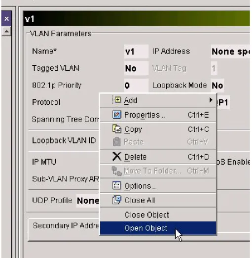
2 Select View>Open Object
To open the object, select Open Object from the View menu, or by right-clicking on the object or the Properties panel and choosing Open Object from the pop-up menu (Figure 4-10).
View Device Configurations
Once you have selected Open Object, a separate window will open to display the properties of that object. This window can only display object properties; you cannot modify the object parameters or launch a wizard from this window.
Figure 4-11: VLAN v1 Properties Displayed in New Window 3 Repeat steps 1 and 2
Select other objects to open, then choose Open Object to display each in its own window. Figure 4-12 shows VLANs v1 and v2 displayed in separate windows, with the Properties panel showing the general VLAN properties of the VLANs object.
Network Provisioning
Figure 4-12: VLANs v1 and v1 Displayed in Separate Windows
Modify Visible Configuration Options
By default, NIM displays all the device configuration objects when the device is expanded. You may not need to change the configuration of some of the objects for your network, or you may wish to suppress display of some of the objects for your session. For example, you can suppress display of IPX configuration options if you don’t support IPX in your network, or perhaps you only want to see the access profile information for a number of devices because you are only modifying them for your current session.
Changing the display of the objects does not affect the ISM Provision server, and only applies to the client you are currently running.
Summary Steps. To modify visible configuration options: 1 Open the Options dialog box
2 Select the Visible Configuration Options tab (if not already visible)) 3 Select the options to display
4 Select Close
Detailed Steps. The following steps are a more detailed explanation of the previous section.
To modify visible configuration options:
VLAN v1
View Device Configurations
1 Open the Options dialog box
Right-click the Network or Properties panel to display a pop-up menu and select Options (see Figure 4-13), or select the Tools>Options menu item to open the Options dialog box.
Figure 4-13: Selecting Options from Pop-Up Menu
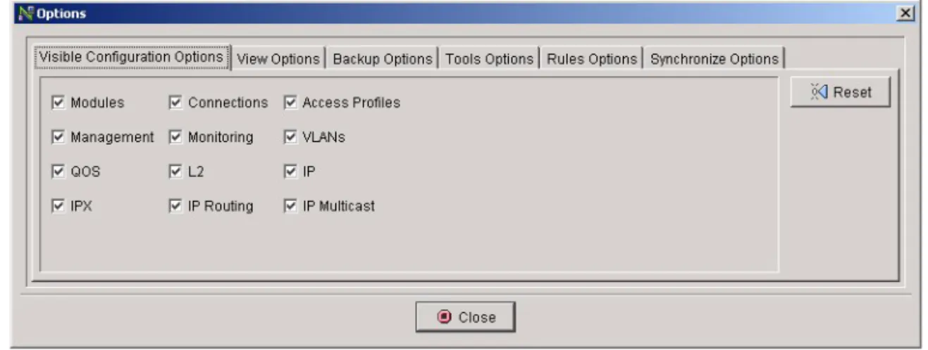
2 Select the Visible Configuration Options tab (if not already visible)
The Visible Configuration Options tab of the Options dialog box should be visible. If not, select it to bring the options forward (Figure 4-14).
Network Provisioning
3 Select the options to display
Check the boxes to display the objects. Uncheck the boxes to hide the objects. The object display in the Network panel changes as you check or uncheck the boxes, so you see your changes immediately.
4 Select Close
Select Close to return to NIM. Since you have not changed any of the configuration, merely suppressed its display, there will be no change to the server icons.
Modify View Options
The two view options that can be modified are Use Tabs for Object Panels and Track Window Dimensions.
Use Tabs for Object Panels controls object display in the Properties panel. With tabs enabled, each time you select an object to view, a tab is created in the Properties panel so you can quickly return to that object without having to select it in the Network panel. However, the Properties panel can become cluttered if you select a large number of different objects during a session.
Track Window Dimensions allows the client to track you as you resize client windows. The next time the client opens a window, it will use the latest size you chose. If Track Windows Dimensions is not selected, you can choose the default window size from the View Options tab of the Options dialog box
Steps. To modify view options: 1 Open the Options dialog box
For details, see the step, “Open the Options dialog box”, in the task,“Modify Visible Configuration Options”.
2 Select the View Options Tab 3 Modify settings
Create and Modify Network Device
Configurations
The heart of ISM Provision is the ability to roll out network changes in a controlled manner. The powerful provisioning functions allow you to take existing device
Create and Modify Network Device Configurations
configurations and modify them for new devices, create templates for typical device configurations, and coordinate changes across many devices.
In this section you will find instructions how to: • Add a New Device
• Add a Configuration Object • Modify a Configuration Object • Copy a Device or other Object
• Save Changes Without Changing Network Configuration • Change an Unmanaged Device into a Managed Device • Change an Unmanaged Device into a Managed Device
Add a New Device
You can add a new device configuration into the Network panel of the Network Provision view. The device you add will have a configuration similar to an
unconfigured device. Once the device is added you can make, save, and/or commit changes to the configuration. Typically, you would add a device this way if you are planning to add a new device that will have a very simple configuration, or whose configuration will be very different from any other devices in your network.
If you have an existing device in NIM whose configuration is similar to the new device configuration, you will want to copy the device and modify it for the new device. See the section, “Copy a Device or other Object” for more information.
If you have an existing device in your network and you want to add that device and its current configuration into ISM Provision, see the section, “Add a Device to the Network Inventory” in Chapter 5, “Managing the Network Inventory”.
Summary steps. To add a new device: 1 Select a folder in the Network panel 2 Launch the Create Device wizard 3 Enter a device name (or IP address) 4 Modify the other properties
Network Provisioning
Detailed Steps. The following steps are a more detailed explanation of the previous section.
To add a new device:
1 Select a folder in the Network panel
If the Network panel is not open, select it from the View menu. Once the panel is open, click the device folder into which you will add the new device.
2 Launch the Create Device wizard
To launch the Create Device wizard, select Edit>Add>Device from the menu, or right-click in either the Network or Properties panels and select Add>Device from the pop-up menu. The Create Device wizard will appear.
3 Enter a device name (or IP address)
Enter the device name into the Create Device wizard. You must give the device a unique name to identify it for ISM Provision. Use the name or IP address that you plan to use when the device will be deployed, otherwise use a temporary name. If possible, do not use a temporary name. Since ISM Provision uses the name as a unique key for the device, device names cannot be directly changed. To change the name at a later time you will need to copy the device, paste it back into the Network panel and give it a new name, then delete the original device entry.
4 Modify the other properties
Use the drop-down list to choose the type of device and the image you plan to use. As you make your choices, the wizard may allow other choices based on your selections. Use the Next button to advance through the wizard choices.
If you select the Managed Device checkbox in the Create Device wizard, and fill in the other administrative access information, the configuration you create in NIM will overwrite the existing device configuration when changes are committed to the server. See the section, “Change an Unmanaged Device into a Managed Device”, for more information.
5 Select Finish
When you have made all the selections for the new device, select Finish to close the wizard.
Add a Configuration Object
Anytime you wish to add a configuration object, you will select the parent object that you want to add the object to. For example, when you add a device, you select the
Create and Modify Network Device Configurations
device folder you want to add the device to. When you add a VLAN, you select the VLANs object in the device you want to add the VLAN to.
Summary Steps. To add a configuration object:
1 Select the parent object that will contain the new object 2 Launch the Create wizard (Edit>Add)
3 Enter the key information 4 Enter additional information 5 Select Finish
Detailed Steps. The following steps are a more detailed explanation of the previous section.
To add a configuration object:
1 Select the parent object that will contain the new object
Network Provisioning
Figure 4-15: Selecting the VLANs Object 2 Launch the Create wizard (Edit>Add)
To launch the Create wizard, select the menu item Edit>Add and the object you wish to add. The object choices available to choose vary, depending on the objects that are appropriate to add to the parent object you selected. You can also launch the Create wizard by right-clicking on the parent object. The Create wizard that appears is dependent on the object you are adding. For example, if you are adding a VLAN, the Create VLAN wizard appears. If you are adding a device, the Create Device wizard appears (see Figure 4-16).
Create and Modify Network Device Configurations
Figure 4-16: Launch the Create VLAN Wizard 3 Enter the key information
The field that ends with an asterisk (*) signifies the key information for the newly created object. This is the only information required to create the object, as the other object parameters are set to default values (see Figure 4-17).
Network Provisioning
Figure 4-17: Create VLAN Wizard 4 Enter additional information
Enter any other parameters that you wish to set. In Figure 4-17, the Create VLAN wizard shows a panel titled Config Areas. The Config Areas panel of the wizard represents additional pages of parameters available for you to set. Select the Next button or select the entry in the Config Areas panel to move to another page of parameters. The different wizards have different parameters and differing numbers of additional pages.
5 Select Finish
When you finish setting parameters for the object, select Finish.
Modify a Configuration Object
Any configuration object displayed in the Network panel can be modified. For example, you can modify the parameters of a QoS profile, or you can add or remove ports from a VLAN. The one exception is that key information cannot be modified. See the section, “Key Information”, for more information.
Create and Modify Network Device Configurations
Summary Steps. To modify a configuration object: 1 Select the object to modify
2 Launch the Modify wizard (Edit>Properties) 3 Edit the object properties
4 Select Finish
Detailed Steps. The following steps are a more detailed explanation of the previous section.
To modify a configuration object: 1 Select the object to modify
Display the object you wish to modify and select it by left-clicking. See the section “View a Single Configuration Object” for detailed information on displaying (viewing) an object. For some objects, you may need to select its parent object instead. For example, to change which modules are configured in a device, you might try to select the Modules object and modify it. However, you cannot modify which module is configured from this object. You will need to select the parent device object to modify which module is present in a slot.
2 Launch the Modify wizard (Edit>Properties)
To launch the Modify wizard, select the menu item Edit>Properties. You can also launch the Modify wizard by right-clicking on the object and selecting Properties from the pop-up menu, or you can launch it by typing [CTRL]+E. The Modify wizard that appears is dependent on the object you are modifying. For example, if you are modifying a VLAN, the Modify VLAN wizard appears. If you are
Network Provisioning
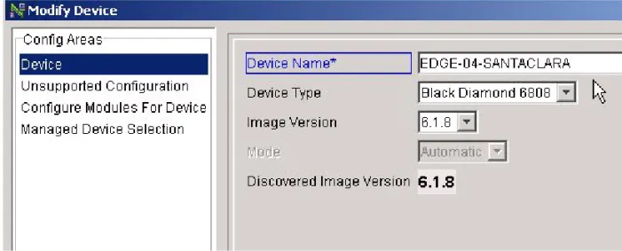
Figure 4-18: Launching the Modify Device Wizard 3 Edit the object properties
Edit any object parameters that you wish to set. In Figure 4-19, the Modify Device wizard shows a panel titled Config Areas. The Config Areas panel of the wizard represents additional pages of parameters available for you to set. Select the Next button or select the entry in the Config Areas panel to move to another page of parameters. The different wizards have different parameters and differing numbers of additional pages.
Create and Modify Network Device Configurations
Figure 4-19: Modify Device Wizard 4 Select Finish
When you finish setting parameters for the object, select Finish.
Copy a Device or other Object
You can copy an existing device to simplify adding a device to your network. Typically, you will copy a device that has a similar configuration to the configuration you will use for the new device. Once the device has been copied, you can modify it.
Summary steps. The following is a short summary of the steps to copy an existing device.
To copy a device or other object: 1 Select the object to copy 2 Select Copy
3 Select the paste location 4 Select Paste
5 Enter a device name (or IP address)
Network Provisioning
Detailed Steps. The following steps are a more detailed explanation of the previous section.
To copy a device or other object: 1 Select the object to copy
Open the Network panel from the View menu if it is not visible. If the object to copy is not visible, open its parent object by clicking its plus sign, and/or scroll until the object is visible. Once the object to copy is visible, select it by clicking it.
2 Select Copy
You can select Copy by clicking the copy icon, by selecting the Edit>Copy menu item, by right-clicking and selecting Copy, or by pressing [CTRL]+C.
3 Select the paste location
For example, if you copy a device, you will paste it into a device folder. Your device will be added to the folder you select when you paste it (see Figure 4-20). If you copy a VLAN, you would paste it into the VLANs object, the parent of the VLANs on your device. If you attempt to paste an object to a location that is not applicable for that object, the Paste command will be grayed out, and you will not be able to paste until you select an appropriate location. If you attempt to paste on object onto an identical kind of object, you will be notified that you will overwrite the object’s parameters. For example, if you paste a VLAN onto another VLAN, you will overwrite the parameters of that VLAN.
Create and Modify Network Device Configurations
Figure 4-20: Select the Network Device Folder 4 Select Paste
You can select Paste by clicking the paste icon, by selecting the Edit>Paste menu item, by right-clicking and selecting Paste, or by pressing [CTRL]+V (see
Network Provisioning
Figure 4-21: Paste the Device
5 Enter a device name (or IP address)
Enter the device name into the Modify Device wizard (see Figure 4-22). You must give the device a unique name to identify it for ISM Provision. Use the name or IP address that you plan to use when the device will be deployed, otherwise use a temporary name.
If possible, do not use a temporary name. Since ISM Provision uses the name as a unique key for the device, device names cannot be directly changed. To change the name at a later time you will need to copy the device, paste it back into the Network panel and give it a new name, then delete the original device entry.
Create and Modify Network Device Configurations
Figure 4-22: Enter Device Name
6 Select Finish, or modify the other properties
Once you have entered the device name, you may modify the other properties of the device now by selecting Next, or select Finish to copy the device now. All of the properties of the newly copied device, except for the device name, can be modified later.
Network Provisioning
Save Changes Without Changing Network Configuration
If you have made changes to the configurations displayed in the Network Provision view, you can save the changes without changing the configuration on your devices. For example, you would save your changes if you wanted someone to review them before committing them to the network. You would also do this if you have not completed making changes, but want to save them to complete later.
Steps. To save changes without changing network configuration: 1 Select File>Save Changes... or File>Save As Changes...
If you haven’t saved changes yet, you can supply a name for the saved changes. If you have previously saved, the Save Changes... item will save the new changes to the previously saved changes. To save to a different name, use Save As Changes.... 2 Enter a Job Name and Job Description
The time and date are used for the default name. 3 Select Next
The changes are saved, and can be opened at a later time. 4 Select Finish
The changes you have made are still displayed in the Network Provision view, so you can continue to work with the changes, saving periodically.
Remove Changes (Revert to Server State)
Changes that have not yet been committed to the ISM Provision server can be removed. If you wish to save the changes for use later, save the changes as described in the task, “Save Changes Without Changing Network Configuration”. When you revert the server state, any uncommitted changes are removed from the Network Provision view, so this view will correspond to the state of the server.
Steps. To revert to server state:
1 Launch the Revert Changes window
To launch the Revert Changes window, select the Revert icon, select the
Changes>Revert... menu item, or press [CTRL]+Z. The Revert Changes window will appear and ask, “Do you really want to revert and lose all changes you made to this configuration?”. This question is asked regardless of whether you have recently saved your changes.
Create and Modify Network Device Configurations
2 Select Yes
The changes are removed. At this point the Network panel of the Network Provision view displays the current state of the server.
Change an Unmanaged Device into a Managed Device
You should understand the section “Managed and Unmanaged Devices,” before performing this task. The unmanaged device configuration will be loaded onto the physical device that you specify and overwrite any existing configuration present on the device.
Be sure that the image version and the device type specified in the unmanaged configuration matches that of the device. Also be sure that the configuration that you set on the device will allow the device communicator to remain connected to the device. Since the device communicator uses Telnet to connect to the device and enter the configuration commands, if you unconfigure a necessary route, or remove a critical IP address, you will not be able to continue communicating with the device. The situation is identical to the case of manually connecting to the device with Telnet. If you
unconfigure your access, the session will end.
If the physical device already contains an extensive configuration, there may be some errors caused by conflicts between the configuration that is moved to the device and its current configuration. See the last step in this task, “Correct errors (if any), then Commit and Upload”, for information about resolving conflicts.
Summary Steps. To change an unmanaged device into a managed device: 1 Select the device to change
2 Launch the Modify Device wizard (Edit>Properties) 3 Select the Managed Device Selection wizard entry 4 Select Managed Device checkbox
5 Enter Device Address
6 Enter Administrator Login and Password 7 Select Communication Host
8 Select Finish
9 Commit changes to ISM Provision server