Contents lists available atScienceDirect
Radiation Physics and Chemistry
journal homepage:www.elsevier.com/locate/radphyschem
Design of a unique holder for structural modification of ZSM-5 zeolite using
a 10 MeV electron beam generated from an industrial UERL-10-15S2 linear
accelerator
P. Trong Phuc
a, C. Van Chung
b, H.A. Tuan Kiet
c,d, L. Thai Son
a, Van-Phuc Dinh
e,f, T. Dong Xuan
e,f,
T. Duy Tap
g, L. Chi Cuong
h, N.T. Ngoc Hue
a, P. Thi Hue
a, L. Ly Nguyen
a, Le-Phuc Nguyen
i,
D. Van Hoang
a, N. Hoang Long
a, H. Huu Thang
j, N. Van Tiep
k, N. Quang Hung
e,f,∗∗,
L. Anh Tuyen
a,k,∗aCenter for Nuclear Techniques, Vietnam Atomic Energy Institute, Ho Chi Minh City 700000, Viet Nam
bResearch and Development Center for Radiation Technology, Vietnam Atomic Energy Institute, Ho Chi Minh City, 70000, Viet Nam cInstitute of Research and Development, Duy Tan University, Danang City, 550000, Viet Nam
dGraduate School of Education, University of Pennsylvania, Philadelphia, Pennsylvania, 19104, USA eInstitute of Fundamental and Applied Sciences, Duy Tan University, Ho Chi Minh City, 700000, Viet Nam fFaculty of Natural Sciences, Duy Tan University, Da Nang City, 550000, Viet Nam
gUniversity of Science, Vietnam National University Ho Chi Minh City, Ho Chi Minh City, 700000, Viet Nam hUniversity of Technical Education, 1 Vo Van Ngan, Thu Duc District, Ho Chi Minh City, 700000, Viet Nam iVietnam Petroleum Institute, Ho Chi Minh City, 700000, Viet Nam
jDalat Nuclear Research Institute, Vietnam Atomic Energy Institute, Dalat City, 670000, Viet Nam kJoint Institute for Nuclear Research, 6 Joliot Curie, Dubna, Russia
A R T I C L E I N F O
Keywords:
Structural modification of materials MCNP4C2 simulation
UERL-10-15S2 linear Accelerator Electron beam irradiation
A B S T R A C T
The present study reports a design of a unique holder for modifying the structure of ZSM-5 zeolite using electron beam generated from an industrial UERL-10-15S2 linear accelerator with a fixed energy of 10 MeV. The design was made based on a unique holder, namedEDSCholder, which can be simultaneously used as the beam energy degrader and the sample container. Metal materials with different thicknesses and geometries were utilized for simulating and designing (using the Monte-Carlo N particle code) such aEDSCholder. In particular, a mathe-matical formula was proposed for correcting the energy distribution of the electron beam generated from the accelerator, which is not precisely mono-energetic. By comparing the simulated results with the experimental data, we found that the 1050 aluminum alloys with thicknesses of 2.5, 4.7, and 6.8 mm and having a cylindrical geometry are optimal for generating the electron energies of 9.00, 8.04, and 7.12 MeV, respectively. It was also found that, by using a rotated-cylinderEDSCholder in combination with the scanning process of the linear ac-celerator, one can produce a homogeneous dose rate distribution in the samples, which is similar to that ob-tained by using a parallel electron beam. For the structural modification of ZSM-5 zeolite using the above rotated-cylinderEDSCholder, the simulated results indicated that the sample thickness in the range of2.5 3cm can ensure the uniformity of absorbed dose in the irradiated samples. In addition, the influence of sample density (in a range of0.65 0.85g/cm3) and contribution of the X-ray scatterings to the absorbed dose was found to be insignificant and negligible. Moreover, our present design is able to significantly shorten the irradiation time as compared to the conventional design for irradiation using a traditional conveyor system. Hence, this paper proposes an effective solution to reduce the operation cost and enhance the applicability of industrial electron beam accelerators to the structural modification of materials.
https://doi.org/10.1016/j.radphyschem.2020.108948
Received 11 March 2020; Received in revised form 20 April 2020; Accepted 21 April 2020
∗Corresponding author. Center for Nuclear Techniques, Vietnam Atomic Energy Institute, Ho Chi Minh City, 700000, Viet Nam.
∗∗Corresponding author. Institute of Fundamental and Applied Sciences, Duy Tan University, Ho Chi Minh City, 700000, Viet Nam.
E-mail addresses:[email protected](P. Trong Phuc),[email protected](C. Van Chung),[email protected](N. Quang Hung), [email protected](L. Anh Tuyen).
Available online 06 May 2020
0969-806X/ © 2020 Elsevier Ltd. All rights reserved.
1. Introduction
Industrial electron beam (EB) accelerators have been extensively used for the material modification, sterilization of health care produc-tion, preservation of food, environmental treatment, etc (Zimek et al., 1993; Chmielewski et al., 1995; Cleland and Parks, 2003; Vandana et al., 2018). Energy of the EB produced from industrial accelerators is generally in a range of0.1 10MeV, which is suitable for the radiation processing applications (Sarma et al., 1996,2011,2012;Kulkarni et al., 2016;Miloichikova et al., 2016). For modifying the structure of mate-rials, the appropriate energy of the EB depends on the type of each irradiated material and its nature. This leads to a requirement to change the accelerator operation for each specific irradiation case. However, for the EB accelerator, whose electron energy is fixed, any adjustments of operation may increase the cost due to the interruption in production activities and raise also some additional risks (Miloichikova et al., 2016). Several studies have been recently developed with the aim of downgrading the initial kinetic energy of the EB by using an energy degrader instead of the operation adjustment and this topic im-mediately becomes attractive (Miloichikova et al., 2016; Park et al., 2016;Peri and Orion, 2017).
The UERL-10-15S2 linear accelerator (Corad Services Ltd, Russia) (http://vinagamma.com.vn/e) is a popular system among industrial accelerators in the word. This accelerator was equipped at Research and Development Center for Radiation Technology of Vietnam Atomic En-ergy Institute aiming to generate the EB of 10 MeV (1.5 mA) for the intensive irradiation applications of fruits, medical divides, and dried foods, etc. It has been also applied for some studies of structural modification and synthesis of nanomaterials (Vo et al., 2014; Hanh et al., 2017). However, while the EB energy generated from the accel-erator was fixed at 10 MeV, the structural and synthetic studies of various nanomaterials often require lower EB energies. Thus, an ex-perimental design for lowering the EB energy of UERL-10-15S2 linear accelerator to below 10 MeV is of particular importance.
In the area of nuclear power and/or technology, the studies using zeolites as ion-exchange materials in the treatment and management of radioactive wastes have become an important topic. Some studies in Refs (Bursill et al., 1981; Gu et al., 2000). have found that zeolite, whose structure is modified by using irradiation, can become a pro-mising material with excellent ion-exchange properties. A recent report in Ref (Yeritsyan et al., 2013). has indicated that the ion-exchange capacity of clinoptilolite zeolite strongly increases after being irradiated by an EB of 8 MeV. In particular, an enhancement in the sorption of 137Cs cations obtained by using the irradiated clinoptilolite zeolite has been also reported in Ref. (Yeritsyan et al., 2013). This enhancement is associated to the changes in the oxygen state from an interstitial to a lattice site. The reason is that the 8 MeV EB irradiation can create many vacancies of Si and Al atoms in zeolite and, thus, release new sites for the mobile oxygen atoms, leading to a movement of interstitial oxygen atoms to silicon vacancies to form the oxygen (hole) vacancy com-plexes. Such lattice defects caused by the irradiation could be the origin of a substantial amount of ion-exchange centers (Yeritsyan et al., 2013). However, the physical nature of these findings has not been elucidated yet. More detail studies on the effects of EB on the formation of multi-scale defects in zeolite crystals at different electron energies and doses are, therefore, needed. In such case, the UERL-10-15S2 accelerator can be used as a leading equipment, but an appropriate design for the zeolite irradiation must be carried out in advance.
In the present study, we performed the Monte-Carlo simulation to design the energy degraders for the 10 MeV EB generated from the UERL-10-15S2 linear accelerator. These energy degraders are designed to reduce the EB energy to below 10 MeV, which is appropriately used for modifying the structure of ZSM-5 zeolite as suggested by Ref. (Yeritsyan et al., 2013). They are also designed to be the sample con-tainers, which are rotated during the irradiation process. This is, in-deed, the first unique holder design, which can be simultaneously used
as the energy degrader and sample container. This design, thus, is called EDSCholder hereafter. In particular, the simulation design is validated via different comparisons with the real experimental measurements. The quantities used for such validations include the holder materials, thicknesses, and geometries. To correct the electron energy spectrum effected by the Titanium foil, which is used to cover the window of each accelerator scanner, we proposed a mathematical formula to fit the energy distribution of the EB generated from the UERL-10-15S2 linear accelerator. This proposed formula was applied to calculate the peak (Ep) and average (Ea) electron energies and the results obtained are compared with the experimental data taken by using the B3 radio-chromic film dosimeters. In addition, the shape and size of the EB were also measured for removing the influence of inhomogeneous energy distribution on the absorbed doses in the rotatedEDSCholder with the cylindrical geometry (rotated-cylinderEDSCholder). Finally, to find the optimal thicknesses for the samples to be used in ourEDSCholder, we calculated the uniformity of the deposited electron energy in the ZSM-5 zeolite, one of critical materials which has been extensively used for treatment of the radioactive wastes as well as catalyst in the petro-chemical industry (Bursill et al., 1981;Sinha et al., 1995). The results of the present study, thus, contribute an effective solution to reduce the operation cost and enhance the applicability of industrial EB accel-erators in the structural modification of nanomaterials.
2. Methods
2.1. Monte Carlo simulation of theEDSCholders
In this work, the Monte-Carlo N Particle code (MCNP4C2) was used for simulating theEDSCholders (Carinou et al., 2005). The electron (e) and photon (p) modes generated from the accelerators together with interactions of electrons with the matters were applied for all calcula-tions. The pulse height tally (tally F8) was used to simulate the electron energy spectrum, whereas the surface flux (tally F2) was applied to calculate the electron flux (Carinou et al., 2005).
2.1.1. Selected materials for electron energy degradation
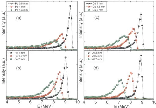
With the aim of degrading the EB energy from 10 MeV to 8 MeV, different materials such as Lead (Pb), Copper (Cu), Iron (Fe), and Aluminum (Al) were selected for simulation. In addition, we built a simple configuration containing a disc-shaped source, which emits a 10 MeV EB. This electron source was set so that the electron irradiation goes directly and perpendicularly to the material plates with different thicknesses. A detector was placed behind the material plates for re-cording the electron energy spectra.
2.1.2. Sample-containing holder
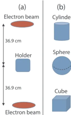
Two disc-shaped EBs (10 MeV) were placed in the opposite direc-tions to the holder, which contains the ZSM-5 zeolite samples as de-picted in Fig. 1 (a). As for the holder, three symmetric geometries having the same volume were selected, namely cylinder (radius
r= 1.5 cm and heighth= 6 cm), sphere (radiusR= 2.1 cm) and cube (2.7 cm × 2.7 cm x 6 cm) (Fig. 1(b)). Since the distance between two EBs (scanner 1 and scanner 2) of the UERL-10-15S2 accelerator is about 73.8 cm (Fig. 2), we fixed the distances from each EB to the holder being equal to 36.9 cm (Fig. 1(a)).
2.1.3. Correction of the electron energy spectrum
windows as in the actual accelerator design. We then employed the one-EB mode in order to have a correct determination of the beam energy distribution.
2.1.4. Uniformity of the absorbed dose in the samples
The uniformity of the absorbed dose in the sample is an important factor for studying the structure of materials before and after the irra-diation. In this study, ZSM-5 zeolite was used as the sample and placed inside theEDSCholder. This sample was divided into many layers, each of which has a thickness of 0.5 cm. The simulation was performed by using the two-EB mode (Fig. 1(a)) with an optimal geometry (cylinder) for theEDSCholder (Fig. 1(b)). The deposited electron energy in each sample layer was calculated by using the tally F8 with the sample (ZSM-5) density of 0.75 g/cm3(Cejka and van Bekkum, 2005).
2.2. Experimental
2.2.1. Electron kinetic energy
In this work, the Wedge instrument (Riso) and alanine B3110 do-simeters (Mejri et al., 2016) were used for measuring the electron ki-netic energy (Fig. 3). The accelerator was set to be operated in the one-scanner (EB) mode. The plate-aluminum alloy degraders with different thicknesses of 3, 5, and 8 mm were placed on the surface of Wedge instrument (Fig. 3(b)). An array of alanine B3110 dosimeters was ar-ranged to record the radiation dose (Fig. 3(a)). These alanine B3110 dosimeters were later heated at 600C for 15 min to keep the color stability.
2.2.2. Shape and size of the electron beam
For measuring the shape and size of the EB, the B3 radio-chromic film dosimeters (Gex) (Mejri et al., 2016) were used. These dosimeters were arranged in a line (in the range of [-12, 12] cm), where the zero position is set up at the center of the irradiated surface behind the plate-aluminum alloy degraders. The heightshfrom the scanner to the plate-aluminum alloy degraders were also manually changed from 20 cm to 60 cm. The experimental setup is illustrated inFig. 4. The accelerator was set to be operated in the one-scanner mode.
3. Results and discussion
3.1. Materials and geometries of theEDSCholder
The degraded electron energy spectra obtained from the MCNP4C2 simulation using different materials are plotted inFig. 5. These plots indicate that all the selected materials (Pb, Fe, Cu, and Al) can be used to effectively reduce the electron energy from 10 MeV to~ 8 MeV. However, their quantitative behaviors are different. For instance, using Pb (average density ~11.34 g/cm3) with an approximate thickness of 1.3 mm could generate an electron energy spectrum around 8 MeV (Fig. 5(a)), whereas to reach 8 MeV using Cu ( ~8.96 g/cm3) and Fe ( ~7.87 g/cm3) one needs the thicknesses of 1.5 mm (Cu) and 2 mm Fig. 1.(a) Simulated design for the irradiated experiment. (b) Geometries of the
EDSCholders.
(Fe) (Fig. 5(b) and (c)). For Al, one needs even a much higher thickness of 5 mm to reach~8 MeV electron energy because this material has very low density ~2.7 g/cm3(Fig. 5(d)). However, the electron energy
distribution generated by using Al degrader is mostly concentrated and symmetric as compared to those obtained by using other materials. The spectrum produced by using this material also has a higher peak-to-background ratio than those calculated using Pb, Cu, and Fe because of its low X-ray yield (Auditore et al., 2011). In addition, Al is a natural material and can be easily used to make the holders with different geometries as required by the present experiment. Therefore, Al was selected to be the most appropriate material for the design of ourEDSCholder. Since, pure Al is soft, has low heat resistance, and can be deformed by temperature arising during the irradiation process, Al alloy should be used instead of pure Al in the present work.
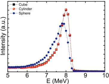
Fig. 6presents the simulated spectra of the 10 MeV EB decelerated by using Al holders (thickness of 5 mm) with different geometries. The results indicate that the spectra obtained by using the rectangular (cube) and cylindrical configurations are almost the same. These spectra have a narrow peak aroundE=8 MeV position and a high peak-to-background ratio as compared to that obtained with the spherical geometry (sphere). This is because the surfaces of both cube and cy-linder are parallel with the cross section of the EB, leading to a similar electron scattering in the Al shell inside the holder, whereas for the sphere, the electron energy distribution is expanded by the in-homogeneous scattering of electrons in it. Hence, the rectangular or cylindrical configuration should be used instead of the spherical one. In the present study, the cylindrical configuration was selected for simu-lation and design of ourEDSCholder owing to its simple manufacture and easy-to-use.
Fig. 3.(a) Alanine B3110 dosimeters. (b) Plate-aluminum degraders and Wedge instrument (Riso) for measuring the electron energy.
Fig. 4.Experimental setup for measuring the shape and size of the EB. Filled black circles indicate the positions where the B3110 dosimeters were placed. Colors in the circular region denote the strengths of the exposed dose rates (highest at the center (red color) and lowest at the outmost region (blue color)). (For interpretation of the references to color in this figure legend, the reader is referred to the Web version of this article.)
3.2. Corrected electron energy spectrum
As discussed in Sec.2.1, the EB energy coming out of the accelerator scanners might not be mono-energetic if the scanners are covered by the Titanium foils. This is proved by our simulation results in Fig. 7 which show that the electron energy distribution after the Titanium foils is no longer mono-energetic. Instead, it has a broad distribution with a peak at around 9.92 MeV, which is less than energy of the initial EB (10 MeV). This distribution is similar to those generated from the microwave linear accelerator (Miller, 2005) and mobile electron ac-celerator (NOVAC7R system) (Pimpinella et al., 2007). Moreover, to be convenient for further calculations and simulations, we have proposed a mathematical function, which can give the best fit to the simulated data, namely
= + + =
f E F Ae z E E
W
( ) z e , 2 p.
0 1 z (1)
Here E E A W, p, , ,andF0 are the electron energy, peak energy, peak height, full width at half maximum (FWHM), and distribution's offset, respectively. The values ofA W, , andF0are obtained from the fittings to the simulated spectra. The average energyEain the energy range of [E E1, 2] is calculated as (Comenetz, 2002)
= E
E E f E dE
1
( ) .
a E
E
2 1 1
2
(2) By using Eqs.(1) and (2)withEp=9.92 MeV, Ea = 9.89 MeV,W= 0.02 MeV,A=0.49, andF0=6.32 × 10⁻³, we obtained the best fit to the simulated data as seen inFig. 7. Thus, the electron energy coming out of the accelerator scanners should be characterized by a distribution with two characteristic parametersEpandEa, instead of a single energy
= E 10 MeV.
3.3. Degraded electron energy
InFig. 8, we plot the simulated electron energy spectra obtained by using theEDSCholder, which contains the 1050 Aluminum alloy plates with the thicknesses of 3, 5, and 8 mm. This Al alloy was selected, instead of pure Al, because of its special properties such as good hardness, heat resistance, and high corrosion resistance (Kramer et al., 2018). Comparison between the simulated and experimental values of EpandEafor different thicknesses of Al alloy is illustrated inFig. 9and Table 1. The experimental values were obtained by using the B3110 Fig. 6.Degraded energy distribution obtained from the MCNP4C2 simulation
using Al holders (thickness of 5 mm) with different geometries.
Fig. 7.Simulated electron energy spectrum and fitting curve of the proposed mathematical function.
Fig. 8.Degraded electron energy distribution obtained from the MCNP4C2 si-mulation by using the 1050 Al alloys with different thicknesses.
dosimeters (Mejri et al., 2016). This figure shows a linear decrease of both experimental and simulatedEp andEavalues when the Al thick-ness is increased. In general, there is a good agreement between the experimental and simulated values. Their relative difference (R), which is in the range of 2.2 6.7% forEpand 3.0 9.8% forEa, does not exceed 10% (Table 1).
In particular, the simulated results indicated that to reach Ep 8 MeV, one needs the 1050 Al alloy with a thickness of 4.7 mm (see the inset ofFig. 9). This thickness is smaller than that obtained for the pure Al because of its higher density (Kramer et al., 2018).Table 2presents the simulated thicknesses of 1050 Al alloys, which can be used to de-grade the electron energiesEp from its initial energy (10 MeV) to ap-proximate values of 7, 8, and 9 MeV. TheseEpvalues will be later used for designing the structural modification experiment of ZSM-5 zeolite presented in the next Section.
3.4. Shape and size of the electron beam
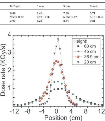
The measured dose rate distributions of the EB at different heights (h=20, 36.9, 45, and 60 cm), which were obtained by using the one-scanner mode of UERL-10-15S2 accelerator, are shown inFig. 10. These results indicate that the EB has a Gaussian dose-rate distribution, whose width increases with increasing the heighth. Thus, the exposed dose distribution in this one-scanner operation mode is not homogeneous. In the actual experiment with the UERL-10-15S2 accelerator, one has to work in the two-scanner mode of the accelerator. In this mode, the EB of the upper scanner moves horizontally from the left to the right, whereas the lower scanner goes in the opposite direction with an identified frequency of 50 Hz as seen inFig. 11. This figure presents the changes of exposed dose rates on the irradiated surface, which are highest at the central region (red color) and lowest at the outmost one (blue color). Obviously, the exposed dose rates in this two-scanner mode are also not homogenous, which may lead to large experimental errors. To have a homogenous distribution of dose rates, we proposed an improved design inFig. 11 in which theEDSCholder having a cy-lindrical shape is rotated during the irradiation (also called the rotated-cylinder EDSCholder). Once the holder is rotated together with the movement of two EBs in the two-scanner mode, the obtained dose rate distribution must be obviously homogenous. This design is similar to the cases that use a parallel EB. Regrading the rotational speed of the EDSCholder, it depends on the total irradiation dose. It has been in-dicated in Ref. (Yeritsyan et al., 2013) that the best irradiation dose for
ZSM-5 zeolite should be in a range of 1013 to 1016 electron/cm2. Therefore, the minimum rotational speed of theEDSCholder should be 1 round per every 13 s.
Table 1
Experimental (Exp.) and simulated (Sim.) values ofEpandEaand their relative differences R(%) obtained by using the 1050 Al alloys with the thicknesses of 0.15 μm, 3, 5, and 8 mm.
Ep(MeV) Ea(MeV)
0.15 μm 3 mm 5 mm 8 mm 0.15 μm 3 mm 5 mm 8 mm
Sim. 9.92 8.87 7.91 6.54 9.89 8.46 7.38 5.71
Exp. 9.7±0.28 8.32±0.29 7.38±0.37 6.16±0.52 9.59±0.37 7.93±0.39 6.75±0.47 5.15±0.64
R(%) 2.22 5.13 6.70 5.81 3.03 6.26 8.54 9.81
Table 2
Degraded electron energiesEp obtained from the MCNP4C2 simulation using the cylinder EDSCholders made of 1050 Al alloy with dif-ferent thicknesses.
Thickness Ep(MeV)
15 μm 9.92
2.5 mm 9.00
4.7 mm 8.04
6.8 mm 7.12
Fig. 10.Measured dose rate distributions of the EB at different heights.
3.5. Uniformity of the deposited electron energy in ZSM-5 zeolite samples
An essential factor in the irradiation experiments of zeolite is the uniformity of the energy that the electrons deposit to the sample, which is called as the absorbed dose. If this absorbed dose is uniformly dis-tributed in the irradiated sample, the systematic error is expected to be smallest. To check the uniformity of deposited electron energy, we performed the simulation for the cylinderEDSCholders (radius of 2 cm) having different thicknesses and containing in them the ZSM-5 zeolite samples. The ZSM-5 sample, which has a density of 0.75 g/cm3and a chemical formula of Nan[H2O]16AlnSi96−nO192(n< 27), was divided into some equal layers, each of which has a thickness of 0.5 cm (see Fig. 12). We used the mean absolute percentage deviations of the ab-sorbed dose (MAPD) to evaluate the uniformity of deposited electron energy in the zeolite sample, namely
=
= =
MAPD
n m
D D
D
(%) 1 100% ,
k n
j m
kj k
k
1 1 (3)
whereDkjandDk are the absorbed dose in thejlayer at thekenergy region and the mean absorbed dose at thekenergy region, respectively. Simulated results inFig. 13 show that the MAPD values increase with increasing the sample thicknesses. For the case 1, there is no sig-nificant difference between the MAPDs for all energiesEp, indicating that its geometry can give an excellent uniformity of deposited electron energy in the zeolite sample. However, since this case 1 contains only two zeolite layers, its application to experiments with large amount of samples is obviously limited. Influences ofEpand sample thickness on MAPDs for the cases 2, 3, 4, and 6 increase gradually and become strongest for the case 6 atEp=9.92 MeV. Case 5 is a special case, in which the presence of the air volume at the top of the sample leads to a substantial increase of MAPDs with energies Ep, except at Ep=
9.92 MeV.
As pointed out in Ref. (Yeritsyan et al., 2013), the electron energy around 8 MeV is the most appropriate energy for the zeolite irradiation process. Thus, the energy region of7 9MeV should be an optimum selection of both MAPDs and sample thicknesses in the present study. In addition, the cases 3 and 4 give the MAPD values being less than 5% at
=
Ep 7.12, 8.04, and 9.00 MeV and sample thicknesses of2 3cm. Therefore, these two cases must be considered as the best ones for the present irradiation experiments, in which the case 4 is preferable be-cause it can accommodate higher volume than the case 3. These para-meters are essential and optimal for the design of our cylinder ED-SCholder.
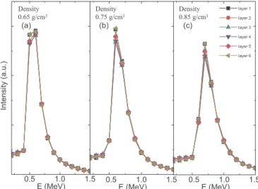
The densities of ZSM-5 samples are also expected to affect the uniformity of the absorbed dose. The effect of ZSM-5 densities was considered in our simulation by using the case 4 withEp=8 MeV and the results obtained are shown inFig. 14. This figure clearly shows the negligible difference between the absorbed doses obtained for the densities in the range of0.65 0.85g/cm3.
The contribution of X-ray scatterings from the shielding concrete around the irradiated area was also taken into account in our simula-tion. The simulation results show that this contribution to the absorbed doses for the ZSM-5 samples varies from 0.9 to 1.2%, only. Moreover, since the effect of the photon on the structure of zeolite was found to be insignificant in comparison with that of the electron (Gu et al., 2000), the contribution of the X-ray scatterings to the samples can be safely neglected.
3.6. Irradiation time and total deposited energy
The electron fluxes inside and outside the cylinder EDSCholder, named asfiandfo, respectively, were simulated by using the tally F2 of the MCNP4C2 code. The obtained ratio of fi/fo is equal to 1.439±
0.004, implying thatfiis higher thanfo. This is due to the production of the secondary electrons when initial electrons interact with the material of the cylinderEDSCholder. This ratio was then used to calculate the irradiation time as well as to correct the total energy deposited in the zeolite samples. Here, the case 4 withEp=8 MeV was selected for our simulation of the irradiation time and total deposited energy.
The electron flux at the surface of the cylinderEDSCholder can be estimated by using the following equation
= ×
f f r
l
2 ,
o s (4)
wherer=2 cm is the radius of the cylinderEDSCholder,l=50 cm is the length of scanning surface, and fs= 6.366 × 10¹³ e/(cm2.s) is the Fig. 12.Illustration of ZSM-5 layers used in the simulation.
Fig. 13.The mean absolute percentage deviation of absorbed dose (MAPD) obtained within the MCNP4C2 simulation for the cases with different sample thicknesses as inFig. 12and at different energies (Ep) as inTable 2.
electron flux at the source. Based on the simulated fi/foratio (1.439±
0.004), we calculated the irradiation timestirr.and total deposited en-ergiesEdep.tot for different doses as follows
=
t D
fi , irr.
(5) =
Edep.tot Edep.fe, (6)
whereD andEdep. are, respectively, the electron dose and deposited
energy of a single electron, whereas fe =f r to 2
irr.is the total electron fluence. The obtained results are presented inTable 3. The value ofEdep.tot in the shell of the cylinderEDSCholder was found to be higher than that in the ZSM-5 zeolite because the density of 1050 Al alloy is higher than the ZSM-5 density. The results presented inTable 3also indicate that the present experimental design is able to significantly shorten the ir-radiation time, namely it takes only about 1365 s when the highest dose of 1016 e/cm2 is used, instead of several days as in the case of con-ventional conveyor irradiation. It is obvious that shortening the irra-diation time is an effective solution to reduce the operation cost of industrial electron accelerators in the structural modification of mate-rials as compared to the traditional irradiation using a conveyor system.
4. Conclusion
In the present study, we reported a holder design for the structural modification of ZSM-5 zeolite materials using electron beams emitted from the industrial UERL-10-15S2 linear accelerator with a fixed energy of 10 MeV. The design, which aims to reduce the electron beam (EB) energy of the accelerator to below 10 MeV, was proposed based on a unique holder of so-calledEDSCholder, which is able to simultaneously use for degrading the EB energy and containing the zeolite samples. The results obtained suggest that the Al alloy is the best material for such a design of ourEDSCholder. In particular, the typical 1050 Al alloy with thicknesses of 2.5, 4.7, and 6.8 mm was found to be optimal for de-grading the electron energy from 10 MeV to 9.00, 8.04, and 7.12 MeV, respectively. In addition, the EDSCholder with a cylindrical geometry was recommended for the experimental studies of material structure modification.
It was found that the electron energy generated from the UERL-10-15S2 linear accelerator had a continuous distribution, instead of a mono-energetic value, due to the use of a Titanium foil (thickness of 0.05 mm) to cover the window of each accelerator scanner. Consequently, a mathematical formula characterized by the peak Ep and averageEa energies was proposed to fit the electron energy dis-tribution. The simulated Ep and Ea values agreed well with the ex-perimental data, namely the relative difference between the experi-mental and simulated values does not exceed 10%. Moreover, we also found that the shape of the EB generated from the UERL-10-15S2 ac-celerator follows the Gaussian distribution, leading to different dose regions on the irradiation surface. To obtain a homogeneous dose rate distribution, we proposed an improved design in which the cylinder EDSCholder is rotatable during the irradiation process, similar to the case that uses a parallel electron beam.
In the considered energy region of7 9MeV for the irradiation of
ZSM-5 zeolite samples, the sample thickness in a range of2.5 3.0cm gives the lowest mean absolute percentage deviations of the absorbed doses (less than 5%) in the sample layers, which are optimal to keep the uniformity of the absorbed dose in the irradiated samples. The influence of sample density in the range of 0.65 0.85 g/cm3 as well as the contribution of the X-ray scatterings on the absorbed dose were found to be insignificant and negligible.
Finally, the present study suggested that the above design is able to significantly shorten the irradiation time as compared to the conven-tional design for irradiation using a tradiconven-tional conveyor system. This design, thus, can be used as an effective solution to reduce the opera-tion cost as well as to enhance the applicability of industrial electron beam accelerators to the structural modification of materials.
Acknowledgements
This work is funded by Ministry of Science and Technology of Vietnam under the Grant Number DTCB: 14/19 TTHN.
Appendix A. Supplementary data
Supplementary data to this article can be found online athttps:// doi.org/10.1016/j.radphyschem.2020.108948.
References
Auditore, L., Barna, R.C., Loria, D., Morgana, E., Trifiro, A., Trimarc, M., 2011. Design of an e-gamma converter for a 10 MeV electron beam. In: Proceedings of 2011 Particle Accelerator Conference (New York), pp. 2184–2186.
Bursill, L.A., Thomas, J.M., Rao, K.J., 1981. Stability of zeolites under electron irradiation and imaging of heavy cations in silicates. Nature 289, 157.
Carinou, E., Stamatelatos, I.E., Kamenopoulou, V., Georgolopoulou, P., Sandilos, P., 2005. An MCNP-based model for the evaluation of the photoneutron dose in high energy medical electron accelerators. Phys. Med. 21, 95.
Cejka, J., van Bekkum, H., 2005. first ed. Zeolites and Ordered Mesoporous Materials: Progress and Prospects, vol. 157 Elsevier.
Chmielewski, A.G., Iller, E., Zimek, Z., Romanowski, M., Koperski, K., 1995. Industrial demonstration plant for electron beam flue gas treatment. Radiat. Phys. Chem. 46, 1063.
Cleland, M.R., Parks, L.A., 2003. Medium and high-energy electron beam radiation pro-cessing equipment for commercial applications. Nucl. Instrum. Methods Phys. Res. B 208, 7.
Comenetz, M., 2002. Calculus: the Elements. World Scientific.
Gu, B., Wang, L., Wang, Sh, Zhao, D., Rotberg, V.H., Ewing, R.C., 2000. The effect of H+ irradiation on the Cs-ion exchange capacity of zeolite -NaY. J. Mater. Chem. 10, 2610.
Hanh, T.T., Thu, N.T., Quoc, L.A., Hien, N.Q., 2017. Synthesis and characterization of silver/diatomite nanocomposite by electron beam irradiation. Radiat. Phys. Chem. 139, 141.
http://vinagamma.com.vn/e http://vinagamma.com.vn/en/electron-beam-accelerator-443.html.
Kramer, G.R., Mendez, C.M., Ares, A.E., 2018. Evaluation of corrosion resistance of commercial aluminum alloys in ethanol solutions. Mater. Res. 21, 1.
Kulkarni, N.S., Dhingra, R., Kumar, V., 2016. Physics design of a 10 MeV, 6 kW travelling wave electron linac for industrial application. Pramana - J. Phys. 87, 74 1.
Manual of UERL-10-15S2 Linear Accelerator. Copyright. by Corad Services Ltd (Russia).
Mejri, A., Farah, K., Hosni, F., Chatti, J., Trabelsi, H., Trabelsi, Z., Kraiem, M., 2016. Dosimetry commissioning of Tunisian electron beam accelerator. Arabian J. Sci. Eng. 41, 2333.
Miller, R.B., 2005. Electronic Irradiation of Foods: an Introduction to the Technology. Springer-Verlag US.
Miloichikova, I.A., Stuchebrov, S.G., Danilova, I.B., Naumenko, G.A., 2016. Simulation of the microtron electron beam profile formation using flattening filters. Phys. Part. Nucl. Lett. 13, 890.
Park, J.I., Ha, S.W., Kim, J.I., Lee, H., Lee, J., Kim, I.H., Ye, S.J., 2016. Design and eva-luation of electron beam energy degraders for breast boost irradiation. Radiat. Oncol. 11, 112 1.
Peri, E., Orion, I., 2017. Shielding calculations for industrial 5/7.5MeV electron accel-erators using the MCNP Monte Carlo Code. EPJ Web Conf. 153, 1 03011.
Pimpinella, M., Mihailescu, D., Guerra1, A.S., Laitano, R.F., 2007. Dosimetric char-acteristics of electron beams produced by a mobile accelerator for IORT. Phys. Med. Biol. 52, 6197.
Sarma, K.S.S., Sabharwal, S., Kalurkar, A.R., Chaudhary, C.V., Khader, S.A., Deshpande, R.S., Majali, A.B., 1996. EB crosslinking of polyethylene ’O’ rings: optimisation of process parameters. J. Radioanal. Nucl. Chem. 206, 341.
Sarma, K.S.S., Rawat, K.P., Benny, P.G., Kader, S.A., 2011. Developments in electron beam processing technology. BARC News Lett 323, 38.
Sarma, K.S.S., Benny, P.G., Khader, S.A., Patkari, R.K., 2012. Safety aspects of a medium Table 3
Irradiation timetirr.and total deposited energiesEdep.tot in theEDSCholder's shell and ZSM-5 sample.
Electron dose tirr. Edep.tot inEDSCholder's shell E
dep.tot in ZSM-5
(e/cm2) (s) (Joule) (Joule)
1012 0.14 3.20 2.89
1013 1.36 32.05 28.94
1014 13.65 320.46 289.41
1015 136.50 3204.60 2894.10
energy industrial electron beam accelerator being utilized for technology demon-stration and commercial operations. Indian J. Pure Appl. Phys. 50, 805.
Sinha, P.K., Panicker, P.K., Amalraj, R.V., Krishnasamy, V., 1995. Treatment of radio-active liquid waste containing caesium by indigenously available synthetic zeolites: a comparative study. Waste Manag. 15, 149.
Vandana, S., Benny, P.G., Palani Selvam, T., 2018. Comparison of measured and Monte Carlo-calculated electron depth dose distributions in aluminum. Indian J. Pure Appl. Phys. 56, 48.
Vo, K.D.N., Kowandy, C., Dupont, L., Coqueret, X., Hien, N.Q., 2014. Radiation synthesis
of chitosan stabilized gold nanoparticles comparison between e-beam and γ irradia-tion. Radiat. Phys. Chem. 94, 84.
Yeritsyan, H., Sahakyan, A., Harutyunyan, V., Nikoghosyan, S., Hakhverdyan, E., Grigoryan, N., Hovhannisyan, A., Atoyan, V., Keheyan, Y., Rhodes, C., 2013. Radiation-modified natural zeolites for cleaning liquid nuclear waste (irradiation against radioactivity). Sci. Rep. 3, 2900 1.