1. Introduction
Multi-antenna downlink transmission for up to four antennas has been specified in the Long term evolution (LTE) of Third generation wideband code division multiple access (3G WCDMA) standards for targeting higher data rates [1]. Beamforming has been defined in LTE as one of the multi-antenna transmission schemes [1]. These schemes can be implemented as Multiple-input multiple-output (MIMO) or MISO systems. At high data rates MIMO can provide large capacity improvement. MISO system retains its importance as it limits the cost and size of the mobile terminal. Also as stated in [2], at fix data rates, extra bandwidth available with MIMO becomes unnecessary as the system tends to be operating in power limited mode rather than in band limited mode.
Various Adaptive transmit beamforming (ATBF) algorithms have been proposed for MISO Frequency division duplex (FDD) systems (where the forward
channel is unknown) to maximize received power [2]-[5]. This maximization is provided by beamforming gain through formation of a beam in the desired direction and fading diversity gain through feedback from the mobile [3]. In [5] all forward channel coefficients are fed back which makes it impractical for wireless systems due to constraints in feedback channel [3].
In slow fading channels the rest of the ATBF methods [2]-[4] give optimum performance, while in fast fading channels they are outperformed by diversity Space time codes (STC) [2] [3]&[6]. The reason is that for fast fading channels the channel changes at a rate difficult for ATBF algorithms to track and STC (which does not require tracking) gives better performance. In [7] & [8] a combination of STC and beamforming was proposed. Knowledge of mean values of the forward channel and estimate of the forward channel is required in [7] and [8] respectively, necessitating large feedbacks. In order to improve performance in fast fading channels an algorithm was
Beam Pattern Evolution of an Adaptive Transmit Beamspace
Beamformer
S. S. Irfan Hussain
1and M. Imran Shiekh
11 Electrical Engineering Department, University of Engineering & Technology (UET), Lahore, Pakistan
Abstract
This paper presents evolution of beam pattern of an Adaptive transmit beamspace beamformer(ATBBF) at the base station of a 3rd generation code division multiple access (3G-CDMA) system for Multiple input single output (MISO) per user wireless channel, bridging the respective interest of antenna and signal processing groups. ATBBF establishes a set of orthogonal beams in space, each of which is weighted by an adaptive beamspace weight. The overall beam pattern is determined by the superposition of beamspace weighted orthogonal beams. The ATBBF algorithm perturbs beamspace weights at the base station to generate even and odd beamspace weights which are time multiplexed with the pilot signal. The mobile feedbacks a single bit to indicate which of the two beamspace weights delivered more power. This weight becomes the new beamspace weight. The beamspace weights and the beam pattern continue to be updated, finally converging to the optimum. Simulations in single, double and triple multipath wireless channels demonstrate the unique evolution of ATBBF's beam pattern in relation to the convergence of its beamspace weights. The dependence of magnitude and convergence time of a beamspace weight upon the multipath wireless channel is clarified to understand this evolution.
Key Words
:Transmit beamforming, adaptive beamforming, beamspace beamforming, linear antenna array, beam patternneeded that could provide both spatial diversity and beamforming with efficient feedback.
An ATBBF combines beamforming and spatial diversity by forming a beam in the desired direction by superposition of weighted orthogonal beams in space [9] & [10]. Therefore in [11], an ATBBF algorithm for ATBF was devised where the orthogonal beams were adaptively weighed. The feedback was based on the approach of Gradient sign feedback algorithm (GSF) [3], which has the most efficient feedback consisting of only one bit. Hence this method was named Beamspace gradient sign feedback algorithm (BGSF). This paper demonstrates and explains the unique evolution of ATBBF's beam pattern in relation with its beamspace weights as BGSF updates them towards optimum values. Dependence of beamspace weight's convergence time and magnitude on the multipath wireless channel is comprehended to explain the progression of ATBBF's beam pattern. The paper has been organized as follows: In section 2, the beam pattern of ATBBF is derived. Section 3 shows how the BGSF algorithm adapts beamspace weights of ATBBF. The last section presents simulations and explains the relationships and dependences observed in them followed by conclusions.
2. Beam pattern of an adaptive
transmit beamspace beamformer
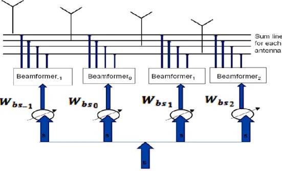
ATBBF can consists of a maximum of N transmit beamformers on an N element linear array (as shown in Figure 1) to produce orthogonal beams as shown for a receive beamspace beamformer in [9]. The array is a standard Uniform linear array (ULA) with inter element distance d equal to half of the carrier wavelength i.e. .
2d
d This array is aligned with the z-axis and centered at the origin. Further it consists of N = 4 isotropic antenna elements. The position vector of the nth antenna array element is
z n n z a
p with zn
n N
d2 1
. Each of the N
transmit beamformers forms one orthogonal beam. The orthogonal beam directed towards broadside
) 90
(
is called the center beam. Center beam is formed by a Transmit beamformer (TBF) that weighs each element of the above ULA with uniform weights) / 1
(wn N . This ULA has isotropic elements therefore its beam pattern is equivalent to its array factor. Neglecting mutual coupling, its beam pattern/array factor from [12] is:
cos2
2 cos sin sin 1 ) (
N NB (1)
Other orthogonal beams are formed on either side of the center beam by shifting it by specified values. This shift results in beams that are apart from each other by 2/N in spatial space (cos). Thus beams are mutually orthogonal as well as uniformly spread out in the total spatial span of 2 (cos can vary from -1 to -1). The beam pattern of nth TBF/orthogonal beam (from Eq. 1) for N even becomes:
2 22 cos
2
2 , 1,...
sin cos sin
1 )
( N N N
n N
n n
N
B
(2)E.g. for N=4, 1,... 1,0,1,2 2
2
N N
n . This gives
the following values in spatial space where the orthogonal beams are shifted i.e.
. 1 , , 0 , ) 2 , 1 , 0 , 1 ( cos 2 1 2 1
2
N
In terms of elevationangle
this amounts to 120o, 90o, 60o, 0o where the orthogonal beams are directed. The beam pattern of ATBBF is the sum of weighted beam patterns of thetransmit beamformers i.e.:
) ( ) ( 2 2 1
bs nn
ATBB W B
B n N N
(3)
2 cos sin cos 2 sin 2 1 2 2
N n bs n N N W n N N Here n bsW is the nth complex beamspace weight for weighing the nth. TBF beam pattern. For N = 4, beamspace weights
2 1 1, bs , bs , bs
bs W W W
W
o
weigh
beams directed at 120o, 90o, 60o, 0o respectively. Beam pattern of ATBB can also be expressed in terms of weights of the ULA elements for each TBF. Let w(n) be the N1 weight vector having weights of the
nth TB for all N elements of ULA. The weight vectors are also mutually orthogonal as their corresponding beam patterns are mutually orthogonal. Beam pattern of nth. TBF in terms of its weight vector is from [12]:
) ( ) ( )
( v k w n
Bn
kH (4) Here k2ar denotes the wave number [9] ofN plane waves from N respective antennas that become parallel at a far field point in direction of ar.
While the array manifold vector vk(k) defined in [9] and used in [12] evaluates for this ULA to:
cos 1 cos 1 cos 0 2 1 2 1 2 1 1 1 ) ( N N N N o N j j j p jk p jk p jk k e e e e e e k v (5)ATBBF beam pattern becomes from Eq. 3 and Eq. 4: n N N bs H k n
ATBB v k w nW
B ( ) ( ) ( )
2 2 1
(6)In order to accommodate all weight vectors in a matrix we define a NN beamspace matrix Bbs, also
known as the butler matrix. w(n) weight vector is assigned to (nN/2)th column of Bbs. Also we
define N1 beamspace weight vector wbs having all
the complex
n
bs
W beamspace weights. Incorporating Bbs and wbs in Eq. 6 we get:
bs bs H k
ATBB v k B w
B (
) ( ) (7)3. BGSF Algorithm
ATBBF as described above is at the base station of a 3G WCDMA system in a MISO wireless channel environment with single, double or triple multipath. Discrete time signal representation has been used by using the nyquist sampling theorem.
The signal to be sent to the mobile is s as shown in Figure 1. Assume that there are L multi paths. clis the N1 channel vector representing all the complex channel coefficients of the lth multipath. The nth
channel coefficient of cl represents the path from the th
Thus the received signal at the mobile (neglecting noise) from Eq. 7 and Figure 1 becomes:
L
i bs bs
bs bs H
l s m l
i w B i w B c m r 1 ) ( || ) ( || ) ( ) ( (8)
L i bs bs bs Hl s m l
N i w i w B c 1 ) ( || ) ( || ) ( (9)
Multiple path terms in Eq. 9 have delays that are integral multiple of the Nyquist sampling time. Here
i
represents the ith algorithm iteration of BGSF whileis the Nyquist sampling time index. The beamspace weights have been normalized so that concentration is on their direction rather than on their magnitude. Also, as columns of the beamspace matrix are orthogonal to one another i.e.
N bs H bsB
B 1
therefore denominator in Eq. 8 simplifies to
N w w B w B w
Bbs bs|| ( bs bs)H bs bs || bs||
||
In this same ith iteration, wbs(i), is also perturbed at the base station by a N1 zero mean normal Gaussian vector p (having an autocorrelation matrix 21) to generate two pilot weights
e
bs
w and
o
bs
w as follows:
) ( || ) ( || ) ( )
(i w i w i p i
wbs bs bs
e
(10)) ( || ) ( || ) ( )
(i w i w i p i
wbs bs bs
o
(11)
is the adaptation rate parameter of the algorithm. There is provision of pilot signal sp in the forward link of 3G CDMA systems for channel estimation at the mobile receiver used in coherent detection at the mobile [1]. A time slot of durationQ=Mm (where M is any integer) is defined. A measurement interval equivalent to a specified integral multiple of 2Q is also defined. The pilot signal is sent with
e
bs
w and
o
bs
w in consecutive time slots i.e. with
e
bs
w during even slots
Wm
even
and witho
bs
w
during odd slots
Wm
odd
. The received signal dueto the pilot signal in the even slot becomes (neglecting noise) from Eq. 9:
L i bs bs bs H lpe s m l
N i w i w B c m r e 1 ) ( || ) ( || ) ( ) ( (12)
While in the odd slot (neglecting noise) it is:
L i p bs bs bs H lpo s m l
N i w i w B c m r o 1 ) ( || ) ( || ) ( ) ( (13)
These pilot signals deliver even power PeR(m) and odd power PoR(m) in respective slots to the mobile. PeR(m) is defined as square of r (m)
e
p divided by unit resistance [13] i.e. PeR(m) is:
N i w l m s i w B c e bs p e bs bs H l L l || ) ( || ) ( ) ( 1 × N i w u m s i w B c e bs p e bs bs H l L u || ) ( || ) ( ) ( 1 (14)
Thus PeR(m) is sum of L2 product terms. Product terms having lu become zero. Hence Eq. 14 becomes N i w c i w B i w B c l m s e bs l H bs bs e bs bs H l p L l e 2 2 1 || ) ( || ] )) ( )][( ( [ || ) ( ||
(15)
The power of the pilot sequence is one. There are scalar terms in each bracket. Scalar multiplication is commutative therefore reverse the order of the brackets to get:
N i w i w B c c B i w m P e bs bs bs H l l H bs H bs L l l R e e e 2 1 || ) ( || ) ( ) ( ) (
(16)
Here )
1
L l H ccR can be substituted as the channel correlation matrix as defined in [3] & [6].
Similarly, PoR(m) will have same expression consisting of
o
bs
w instead of
e
bs
w . Both above powers are summed separately for all even and odd slots in a particular measurement interval. The difference between summed even PeR(m) and odd
) (m PoR
power is found. The sign of this difference is fed back to the base station.
If the sign is positive the pilot signal sent with
e
bs
w in even slots gave more power to the mobile while if the sign is negative pilot signal with
o
bs
w
gave more power in odd slots. Consequently, at the base station the beamspace weight wbs for the next
th
i 1)
( algorithmic iteration is
e
bs
w for positive feedback, while it is
o
bs
w for negative feedback. The beamspace weights at the base station continue to be updated in this manner by BGSF, finally converging to those weights that result in forming a main lobe in the direction of the mobile.
4. Simulations and results
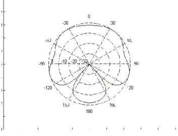
An ATBBF consisting of four TBF (as shown in Figure 1) on a four element ULA aligned along z-axis is simulated. BGSF algorithm is used to update ATBBF's beamspace weights. Initially the beamspace weights are taken as unity. The corresponding beam pattern (found by inserting these weights in Eq. 7) is the initial beam pattern (shown in Figure 2) for all simulations.
Figure 2: Initial beam pattern of ATBBF
Three wireless MISO channel scenarios have been separately simulated. The first, second and third channel scenarios consist of single, double and triple multipath having one, two and three channel vectors respectively. In a single multipath environment, signal energy arrives along a single path from an antenna to a mobile. While in double and triple multipath environments, signal energy from an antenna follows respectively two and three paths towards the mobile. The gradual update of ATBBF's normalized beamspace weights by the BGSF algorithm and its corresponding normalized beam pattern have been depicted to show how this beam pattern gradually evolves into single / multiple lobes as the BGSF algorithm updates its beamspace weights. The relationship of beamspace weight's convergence time and its magnitude on various multipath wireless channels is illustrated to clarify this progression of ATBBF's beam pattern.
4.1 Simulation and results for a single
multipath channels
In the first scenario the signal energy arrives at the mobile along a single path at
105o with respect to ULA at the base station (i.e. the channel vector is the array manifold vector in Eq. 5 with
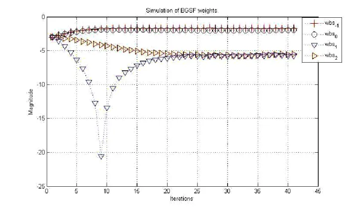
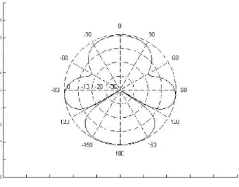
105o). Beam patterns of ATBBF for 10th and 40th iterations of BGSF are shown respectively in Figure 3 and Figure 4. Convergence of beamspace weights is shown in Figure 5. Beamspace weight1
bs
W and
e
bs
W weighs the orthogonal beams directed at
120o ando 90
respectively. The multipath signal direction
105o is in between the direction of these two beams. At the 10th iteration both1
bs
W and
e
bs
W converge and attain a magnitude of -2dB (Figure 5) resulting in the formation of a main lobe directed at
105o (Figure 3), while the other two weights have not yet converged (Figure 5). By the 40th iteration the other weights i.e.1
bs
W and
2
bs
W have
already converged to a lower magnitude level of -6dB (Figure 5). This further enhances the directivity of the main lobe in the desired direction, but at the cost of an increased side lobe level (Figure 4). This shows that the convergence time and converged magnitude of a beamspace weight is dependent upon the proximity of its orthogonal beam to the multipath signal direction.
Figure 3: Beam pattern of ATBBF at 10th iteration of BGSF for multipath at
105oFigure 4: Beam pattern of ATBBF at 40th iteration of BGSF for multipath at
105oProximity is in terms of spatial space (cos) and not in terms angle of elevation (). This is verified by a second single multipath channel scenario with multipath signal direction at
30o. This direction is equidistant to orthogonal beam directions of1
bs
W and
2
bs
W in terms of
. However2
bs
W acquires greater converged magnitude of 0db as compared to -5db of
1
bs
W and converges earlier. The reason is that in spatial space this direction (cos30=0.87) is more towards orthogonal beam direction of
2
bs
W (cos0=1). Thus closer the orthogonal beam is to a multipath signal direction in spatial space, greater is the magnitude of its beamspace weight on convergence and shorter is the time of convergence of its beamspace weight.
In order to verify the convergence of beamspace weights and beam pattern to optimal values, Eigen analysis was performed on the channel correlation matrix R for the first channel scenario. The principal eigenvector q was found to be:
, 36 . 0 34 . 0 , 5 . 0 03 . 0 , 32 . 0 38 . 0
[ i i i
q
q is the optimal weight vector of TB for R [3]&[6]. The optimal beam pattern can be found by substituting w(n)=q in TBF's beam pattern expression i.e. Eq. 4. This beam pattern completely matches with the beam pattern of ATBB in the 40th iteration (Figure 4). Hence optimal beam pattern and beamspace weights of ATBB are achieved.
5. Simulation and results for double
multipath
In this simulation, signal energy for the first multipath comes along
0, while for the second it comes along
90, with respect to the ULA at the base station. Beam pattern of ATBBF for 10th and 40th iterations of BGSF are given in Figure 6, and Figure 7 respectively. Convergence of beamspace weights is depicted in Figure 8. The two paths are at angles 0
and
90 where the orthogonal beams weighed by2
bs
W and
e
bs
W are directed respectively.
At the 10th iteration both
2
bs
W and
e
bs
W converge and acquire -1.5dB magnitude (in Figure 8) resulting in the formation of lobes in the direction of
0
and
96 (in Figure 6). By the 40th iteration other weights i.e.1
bs
W and
1
bs
W have already converged to lower magnitudes around -20dB (in Figure 8). This further enhances the directivity of lobes at
0and
96 (in Figure 7).Figure 6: Beam pattern of ATBBF at 10th iteration of BGSF for first and second multipath at
0
and 90 respectivelyFigure 7: Beam pattern of ATBBF at 40th iteration of BGSF for first and second multipath at
0
Finally, as the required directions were along orthogonal beams, lobes were not achievable simultaneously in both directions. This results in a slight shift in the direction of one of the two lobes.
In order to confirm convergence to optimal beamspace weights and beam pattern the two principal eigenvectors of the channel correlation matrix R for this channel scenario were found. One of them is:
T
i
i
q
[
0
.
58
,
0
.
41
,
0
.
58
,
0
.
41
]
The optimal beam pattern (corresponding to
w(n)=q in Eq. 4) completely matches with the final beam pattern of BGSF in the 40th iteration (Figure 7). Hence optimal beam pattern and beamspace weights are achieved.
This double path simulation confirms the findings from single multipath case. There are also some subtle observations not seen in single multipath case. Table 1 depicts observations for several double Figure 8: Convergence of beamspace weights of ATBBF for first and second multipath at
0
and 90 respectivelyTable 1: Double multipath channel simulations Multipath signal direction
(in degrees)
Convergence time of beamspace weights (No of iterations)
Normalized magnitude of converged beamspace weight (dB) First Second Wbs1 Wbso Wbs1 Wbs2 Wbs1 Wbso Wbs1 Wbs2
0 105 13 9 12 7 -4 -4 -8 -1
0 108 9 12 14 7 -3 -5 -8 -1
0 112 3 14 12 8 -2 -7 -9 to -10 -1
0 116 3 14 15 11 -2 -10 -11to-12 -1
multipath simulations. Here the first multipath signal direction remains along
0 while the second is gradually shifted from
105 to
120.The third and fourth row of Table 1 shows that the convergence time of
1
bs
W becomes less than that of
2
bs
W . This is despite the fact that there is a multipath direction along orthogonal beam of
2
bs
W while there is none along orthogonal beam of
1
bs
W . The reason is that firstly the second multipath direction is close to the orthogonal beam of
1
bs
W
This gives
1
bs
W a short convergence time. Secondly second multipath is also not along orthogonal beam of
1
bs
W . This results in giving
1
bs
W a converged magnitude (-2dB) closer to the initial value (-3dB) and lesser in comparison with that of
2
bs
W (-1dB). These reasons cause
1
bs
W to have shortest convergence time. The earlier convergence of
1
bs
W results in forming a lobe towards the second multipath signal direction in advance to the formation of lobe towards the orthogonal beam direction of
2
bs
W .
5.1 Simulation and results for triple
multipath
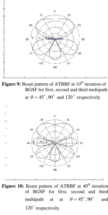
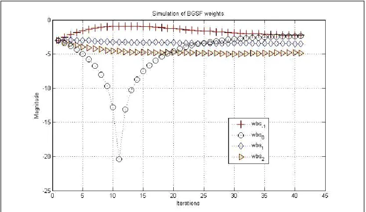
In this triple multipath simulation, signal energy for the first, second and third multipath arrives along
,90 &120 45
respectively, with respect tothe ULA at the base station. Beam pattern of ATBBF for 10th and 40th iterations of BGSF algorithm are in Figure 9 and Figure 10. Convergence of beamspace weights is shown in Figure 11. The first multipath is at
45
. This path is between orthogonal beams at 60
and
0 weighed by1
bs
W and
2
bs
W
respectively.
1
bs
W converges earlier with higher magnitude around -3.5dB (in Figure 11) while
2
bs
W
converges latter with a lower magnitude of -5dB (in Figure 11) because the
45 multipath is closer to the
60 beam weighed by1
bs
W in spatial space. By the 10th iteration both these beamspace weight have converged. This results in the formation of a lobe towards
45 at the 10th iteration (in Fig 9).Theother two paths are at angles
90 and 120
in the direction of the orthogonal beams weighted bye
bs
W and
1
bs
W respectively. Both these weights do not converge by the 10th iteration. Earlier convergence of
1
bs
W is because the multipath signal direction of
45 is close to and not along the orthogonal beam direction of1
bs
W . Thus
1
bs
W has short convergence time and its magnitude at convergence (-3.5dB) is closest to its initial magnitude (-3dB). This gives
1
bs
W the fastest convergence.
Figure 9: Beam pattern of ATBBF at 10th iteration of BGSF for first, second and third multipath at
45,90 and 120 respectivelyFigure 10: Beam pattern of ATBBF at 40th iteration of BGSF for first, second and third multipath at at
45,90 and
By the 40th iteration both
e
bs
W and
1
bs
W converge to around -2.25 dB of magnitude (in Figure 11) which is greater than the magnitude of the other two weights
1
bs
W and
2
bs
W . This happens because there are multipath along the direction of beams weighed by
e
bs
W and
1
bs
W while no multipath exists along beams weighed by
1
bs
W
and
2
bs
W . Convergence of beamspace weight
e
bs
W
and
1
bs
W by the 40th iteration results in the formation of lobes directed at
87 and
126 (in Figure 10). There is a slight shift in the directions of these two lobes from their desired directions as lobes cannot be formed at the same time in both orthogonal directions.Eigen analysis of the channel correlation matrix R for this channel scenario reveals that there is one principal eigenvector q as given below:
T
i i
i
q[0.570.39, 0.020.14, 0.10.1, 0.69]
The optimal beam pattern (corresponding to
w(n)=q in Eq. 4) completely matches with the final beam pattern of BGSF in the 40th iteration (in Figure 10). Hence optimal beam pattern and beamspace weights are achieved.
6. Conclusions
Evolution of beam pattern of ATBBF has been presented. ATBBF generates a set of orthogonal beams equal to or less than the number of antenna elements. A specific weight vector corresponds to an orthogonal beam. Therefore a set of such weight vectors can be applied to form orthogonal beams. In addition, a "beamspace weight" weighs an orthogonal beam's weight vector. The BGSF algorithm updates beamspace weights of the ATBBF in such a way that as the beamspace weights converge, the corresponding beam pattern gradually produces and directs multiple lobes. These multiple lobes correspond to directions of multipath signals towards the mobile. Simulations are produced for single, double and triple multipath scenarios.
Figure 11: Convergence of beamspace weights of ATBBF for first, second and third multipath at
45
The single multipath channel simulation shows that the beamspace weights of the respective orthogonal beams closer (in terms of spatial space) to the multipath signal direction converge earlier to a greater magnitude. This results in ATBBF forming a main lobe exactly towards required direction. Other beamspace weights converge later, ensuing increased directivity of the main lobe. This shows that on applying BGSF, ATBBF forms a main lobe in the desired direction before complete convergence is achieved.
The double multipath channel simulation illustrates that lobes are formed towards the two multipath signal directions. Lobe for multipath signal direction along an orthogonal beam is formed earlier while lobe for other multipath signal direction is formed afterwards in accordance with single multipath channel observations. However lobe for multipath signal direction not along an orthogonal beam can form earlier provided this direction is close to an orthogonal beam's direction. This gives the beamspace weight of that orthogonal beam a short convergence time and a converged magnitude close to its initial value. This leads to its earliest convergence forming a lobe in advance.
In the triple multipath simulation three lobes are formed. Lobe for multipath signal direction not along an orthogonal beam forms first. This is in accordance with the double multipath channel observation of multipath signal direction being close to an orthogonal beam direction. While lobes for multipath signal directions along orthogonal directions are formed later. Acquired magnitudes of converged beamspace weights for double and triple multipath channels follow the single multipath observation. The direction of a lobe in the double and triple multipath simulations has little or no offset from the desired direction.
This demonstrates that ATBBF with BGSF algorithm fairly utilizes the multipath directions present in MISO downlink channels by directing lobes towards them. Furthermore, the beam pattern and beamspace weights of an ATBBF with BGSF algorithm has been shown to converge to optimal beam pattern and beamspace weights for different channel scenarios. Lastly the observed relationships give ATBBF with BGSF algorithm an inherent potential to determine the downlink channel at the transmitter.
7. Acknowledgement
This research has been funded by the University of Engineering and technology (UET), Lahore and Higher education commission (HEC) of Pakistan.
8. References
[1] K. Fazel and S. Kaiser; (2008). Multi-carrier and spread spectrum systems, John Wiley & Sons Ltd.
[2] B. C. Banister and J. R. Zeidler; (2005). IEEE Transactions on Wireless Communications, vol. 4, no.3, 1121-1135
[3] B. C. Banister and J. R. Zeidler; (2003). IEEE Transactions on Signal Processing, vol. 51, no.5, 1156-1171
[4] R.W. Heath Jr and A. Paulraj; )1998). In Conf. Rec. 32nd Asilomar conference on Signals, Systems and Computers, vol. 2, 1073-1078. [5] D. Gerlach and A. Paulraj; (1994). IEEE Signal
Processing Letters, vol. 1, no. 10, 150–152. [6] R. T. Derryberry, S. D. Gray, D. M. Ionescu, G.
Mandyam and B. Raghothaman; (2002). IEEE Communications Magazine, vol. 40, issue. 4, 68-75.
[7] S. Zhou and G. B. Giannakis; (2002). IEEE Transactions on Signal Processing, vol. 50, no.10, 2599-2614.
[8] G. Jongren, M. Skoglund and B. Ottersten; (2002). IEEE Transactions on Information theory, vol. 48, no.3, 611-627
[9] H. L. Van. Trees; (2002). Optimum array processing, John Wiley & Sons, Inc., New York. [10] J. Litva and T. K. Lo; (1996). Digital
beamforming in wireless communications, Artech house Inc., Norwood, MA/
[11] S. S. I. Hussain, M. I. Shiekh; (2007). IEEE International Conference on Electrical Engineering, Lahore, 1-6.
[12] C. A. Balanis; (2005). Antenna theory, analysis and design, John Wiley & Sons, Inc., New Jersey.
[13] B. Sklar; (2006). Digital communications, Fundamentals and Applications, Prentice hall, Upper saddle River, New Jersey.