ISSN: 2252-8938, DOI: 10.11591/ijai.v7.i1.pp42-53 42
Direct Torque Control of Doubly Star Induction Motor Using
Fuzzy Logic Speed Controller
Lallouani Hellali, Saad Belhamdi
Electrical Engineering Laboratory, University of Mohamed Boudiaf- M’sila, Algeria
Article Info ABSTRACT
Article history: Received Nov 26, 2017 Revised Jan 22, 2018 Accepted Feb 25, 2018
This paper presents the simulation of the control of doubly star induction motor using Direct Torque Control (DTC) based on Proportional and Integral controller (PI) and Fuzzy Logic Controller (FLC). In addition, the work describes a model of doubly star induction motor in α-β reference frame theory and its computer simulation in MATLAB/SIMULINK®.The structure of the DTC has several advantages such as the short sampling time required by the TC schemes makes them suited to a very fast flux and torque controlled drives as well as the simplicity of the control algorithm.the general- purpose induction drives in very wide range using DTC because it is the excellent solution. The performances of the DTC with a PI controller and FLC are tested under differents speeds command values and load torque.
Keyword:
Direct Torque Control Doubly Star Induction Motor FLC
Hysteresis Comparator PI Controller
Robustness
Voltage Source Inverter (VSI)
Copyright © 2018 Institute of Advanced Engineering and Science. All rights reserved.
Corresponding Author: Saad Belhamdi
Electrical Engineering Laboratory,
University of Mohamed Boudiaf- M’sila, Algeria Email: [email protected]
1. INTRODUCTION
Doubly star induction machines are one of widely used in many industry segments, due to their advantages in power segmentation, reliability and minimized torque pulsations. Such segmented structures are very attractive for high-power applications, since they allow the use of lower rating power electronic devices at a switching frequency superior than the one frequently utilized in three-phase AC machine drives. This machine have been used in various applications, such as; compressors, cement mills, pumps, rolling mills, fans and mine hoists [1].
The aim of our work is based on the utilization of a simple model of the DSIM, this machine has several advantages such as [2] reliability, robustness and meets the best behavior criteria than the simple induction machine, because it reduces the electromagnetic torque ripples and improves the power factor.
The technique of DTC introduced in 1985 by TAKAHASHI [3, 4] uses a promising strategy due to its usefulness and implementation simplicity. Many studies have allowed a rigorous modeling of this approach [4, 5] Direct Torque Control is a control technique in AC drive systems to get high performance torque control. A Fuzzy Controller is coming to ameliorate (DTC) performance and reduce considerably torque and flux ripples. Fuzzy Logic direct torque control attracts the attention of many researchers the configuration of the fuzzy Logic Controller for the direct torque control. The proposed FLC has been successfully simulated on a simulink model with the help of fuzzy logic toolbox. The performance of the FLC will be compared with the conventional PI controller as well as the testing the use of PI and FLC in case of torque and speed command changes and parametric variations.
So far several types of control are used for the control of such kinds of motors, and to the best of our knowledge; this is the first attempt for a comparative study between PI and fuzzy speed controller of doubly star induction motor using direct torque control.
This paper is structured as follows: In Section 2 the model of the DSIM is presented, a suitable transformation matrix is used to develop a simple dynamic model. We will describe the direct torque control by a fuzzy logic controller; the designed direct torque control models are introduced and explained, in order to improve the static and dynamic control performances of the DSIM in section 3. Section 4 shows simulation results for a comparison between the performances of PI and FLC speed controller of direct torque control of DSIM under various conditions operation (load torque, reference speed, parameter variations). The section 5 concludes this paper.
2. MACHINE MODELING
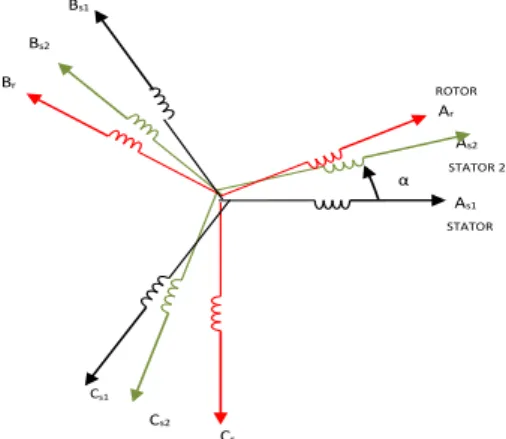
The doubly star induction machine represented by two stators windings: As1, Bs1, Cs1 and As2, Bs2, Cs2 which are displaced by
6
electrical angle .and the rotor windings (Ar, Br, Cr) are sinusoidal distributed and have axes that are displaced apart by
3 2
[6]. The customary assumptions are adopted [7]: 1. Motor windings are sinusoidal distributed. 2. The saturation of magnetic circuit is neglected. 3. The two stars have same parameters.
4. The flux path is linear.
The windings of the DSIM are shown in Figure 1.
Figure 1. Doubly stator winding representation
The voltage equations for stator and rotor circuits for model of the DSIM motor have the following matrix form [8]:
r,abc
dtd + abc r, i r R = 0
abc s2, dt
d + abc s2, i s2 R = abc s2,
abc s1, dt
d + abc s1, i s1 R = abc s1,
V V
(1)
With:
abc s1,
V
,V
s2,abc: Stator voltages. abcs1,
i
,i
s2,abc,i
r,abc: Stator and rotor currents. Cs1Cs2 Cr Bs1
Bs2 Br
As2
As1 ROTOR Ar
STATOR STATOR 2 α
abc s1,
,
s2,abc,
r,abc: Stator and rotor flux.
R
s1 ,
R
s2 ,
R
r : Resistance matrices stator and rotor .In order to ensure the control, the DSIM model expressed in terms of α- and β-axes should be presented by [9]:
r dt d r L + r i r R = 0 r dt d r L + r i r R = 0 s1 dt d s2 L + s1 i s2 R = s2 1 dt d s1 L + s1 i s1 R = s1 2 dt d s2 L + s2 i s2 R = s2 s1 dt d s1 L + s1 i s1 R = s1 V s V s V V (2) Where: s1,V
,V
s2,: Stator voltages αβ components. s1,
i
,i
s2,,i
r, : Stator and Rotor currents αβ components. s1,
,
s2,,
r,: Stator and Rotor flux αβ components.The relation flux (
s1,
s2 ,
s1,
s2 ,
r, and
r) and current (i
s1,i
s2 ,i
s1,i
s2,i
rand
i
r) are [19]:
r i s2 i s1 i m L + r i r L = r i s2 i s1 i m L + r i r L = r r i s2 i s1 i m L + s1 i s2 L = s2 r i s2 i s1 i m L + s2 i s2 L = s2 r i s2 i s1 i m L + s1 i s1 L = s1 r i s2 i s1 i m L + s1 i s1 L = s1 r (3) Where:Lm: Cyclic mutual inductance between stator 1, stator 2 and rotor. Ls1,s2,r: the inductance of a stator 1, stator 2 and rotor respectively.
Ls1+Lm , Ls2+Lm, Lr+Lm: the total inductance of a stator 1, stator 2 and rotor respectively. The electromagnetic torque and the mechanical equations can be written as:
))
s2 i + s1 (i rq -) s2 i + s1 (i rd ( r L m L m L pC
em (4) f K r em C C dt d
3. DIRECT TORQUE CONTROL STRATEGY
The fundamental idea of a direct torque control is a based on the switching tables with hysteresis of torque and stator flux. Using this method, for a the minimization of the commutations of the inverter switches, on the torque/stator flux decoupling, on the control of the PWM generator, DTC requires precise knowledge of the amplitude and angular position of the controlled flux with respect to the stationary stator axis in addition to the angular velocity for the torque control purpose [8, 13]. We don’t require the rotor position in order to choose the voltage vector. This particularity defines the DTC as an adapted control technique of AC machines [10-12].
The principle of DTC operation can also be explained by analyzing the stator voltage equation in the stator flux reference frame [14]:
s00 s1
i s1 R s1
s1
Te V dt (6)
s00 s1
i s1 R s1
s1
Te V dt (7)
s00 s2
i s1 R s2
s2
Te V dt (8)
s00 s2
i s1 R s2 2
s
Te V dt (9)
During the switching interval [0-Te] , Vs >>Rs is we can express:
t VTes s0 s
(10)
3.1. Vectors flux control
By neglecting the stator resistances, (10) implies that the ends of the stator flux vectors will moves in the direction of the applied voltage vectors as shown in Figure 2.
Figure 2.Stator flux vector deviation.
For instance, vectors are selected to increase and decrease the amplitude of flux vectors and ours angular position as:
if
V
(i1)is selected then
sincrease and
sincrease;if
V
(i1)is selected then
sincrease and
sdecrease;if
V
(i2) is selected then
sdecrease and
sincrease;t=Te
Component for torque
t=0
Component for flux
s
0 s
s V Te
α β
if
V
(i-2)is selected then
sdecrease and
sdecrease.The selected voltage vector will be applied to the DSIM at the end of the sample time, as are shown in (10)
Figure 3. Voltage vector selection
3.2. Stator flux estimation
The magnitude of stator flux, which can be estimated as following:
Te V dt
0 s
i s R s
s (11)
The stator flux linkage phasors are given by: 2
1 2 s1
s1 s
(12)
2 2 s 2 2
s2
s (13)
The stator flux linkage phasors positions are:
s1 1 1
s arctg
s (14)
s2 2 s
2 arctg
s (15)
The electromagnetic torque expressions are given by [14]:
s1is1 - s1is1
p 1
Cem (16)
s2is2 - s2is2
p 2
Cem
(17)
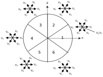
V0,V7 V1 V2 V4
V3
V6 V5 V2 V3 V5
V4
V1 V6 V3
V4 V6
V5
V2 V1
V4 V5 V1
V6
V2 V2
V5 V6 V2
V1
V4
V3 V6
V1 V3
V2
V5 V4
α β
1 2 3
4
2 C 1 C
Cem em em
s1is1 - s1is1 s2is2 - s2is2
p
Cem (18)
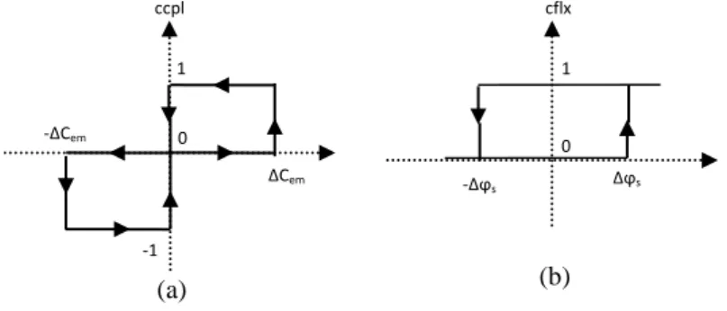
3.3. Flux and torque corrector
The reference values of flux (
s ) and torque (Cem )are compared to their actual values and the resultant errors are fed into a two level hysteresis comparator for the flux and three level hysteresis comparator for the torque, who allows controlling the motor in the two directions of rotation, shown in Figure 4.(a) (b)
Figure 4. Hysteresis comparator, (a): three level hysteresis comparator for the torque, (b): two level hysteresis comparator for the flux
3.4. Elaboration of the switching table
The switching table allows to select the appropriate inverter switching state according to the state of hysteresis comparators of flux (cflx1 and cflx2) and torque (ccpl) and the sector where is the stator vector flux (
s) in the plan (α, β), in order to maintain the magnitude of stator flux and electromagnetic torque inside the hysteresis bands. The above consideration allows construction of the switching table as presented in Table 1.Table 1. Switching table with zero voltage vectors
Sectors 1 2 3 4 5 6
cflx=1
ccpl=1 V2 V3 V4 V5 V6 V1
ccpl=0 V7 V0 V7 V0 V7 V0
ccpl=-1 V6 V1 V2 V3 V4 V5
cflx=0
ccpl=1 V3 V4 V5 V6 V1 V2
ccpl=0 V0 V7 V0 V7 V0 V7
ccpl=-1 V5 V6 V1 V2 V3 V4
3.5. Principe of a fuzzy controller
The control by fuzzy logic permits to get a law of drive, often very effective, without having a precise model of the process, from a linguistic description of the performance of the system. Its strategy is different the one of the automatic classic [15, 16].The fuzzy logic controller is a set of linguistic control rules associated by the dual concepts of fuzzy implication and the compositional rule of inference. The FLC provides an algorithm which can transfer the linguistic control approach based on expert knowledge into an automatic control strategy [20].
Figure 5. Structure interns of a system Fuzzy
ccpl
1
-1 0
∆Cem
-∆Cem
-∆ϕs ∆ϕs
0 1 cflx
Defuzzification Fuzzification Block of decision
Figure 6 in which the linguistic variables are represented by NB (Negative Big), NM (Negative Medium), NS (Negative Small), Z (Zero), PS (Positive Small), PM (Positive Medium) and PB (Positive Big).
Table 2 shows one of possible control rules based on seven membership functions [17].
Figure 6. Fuzzification with seven memberships
Table 2. The fuzzy control rule bases
e
de NB NM NS ZE PS PM PB
NB NB NB NB NB NM NS ZE
NM NB NB NB NM NS ZE PS
NS NB NB NM NS ZE PS PM
ZE NB NM NS ZE PS PM PB
PS NM NS ZE PS PM PB PB
PM NS ZE PS PM PB PB PB
PB ZE PS PM PB PB PB PB
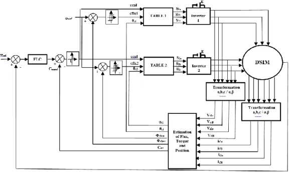
The block diagram for the direct torque control applied to the doubly star induction machine shown in Figure7.
Figure 7. DTC applied to doubly star induction machine (DTC-DSIM)
4. RESULTS AND DISCUSSION
The simulation is done using MATLAB and results are presented here, the motor used in the simulation study is a 4.5 Kw cage rotor, 220 V, 50 Hz. The parameters of the DSIM are summarized in Appendix .the simulation work is passed on three tests of Robustness studies:
4.1. Torque variation
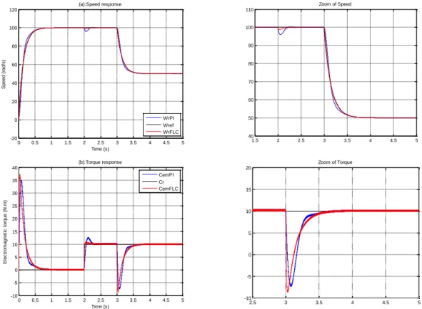
In primary test the Torque variation with the sign of resistant torque (Cr = 10 N.m) for the period of the interval] 2-3.5] s, and the DSIM runs with speed values (100 rad/s).
Figure 8 shows that responses for DTC of DSIM using the proposed PI and FLC, We note that when the motor starts, the speed reaches its reference speed (100 rad/s) , the mechanical torque increases to reach the peak value (35 N.m) with PI and (37 N.m) with FLC and falls down to be close zero value because the motor running with no load. At during] 2-3.5] s we changed the value of load torque to Cr=10N.m, the motor output torque will increase to cover this load. The harmonics magnitude of electromagnetic torque produced by the FLC is inferior than produced by PI.Figure 8 (d), (e), where flux trajectory of PI and FLC controllers is shown from the zero to its rated value, Almost circular flux trajectory with equal amplitudes in both α and β axes.
NBNMNS Z PS PM PB
Figure 8. DTC of DSIM with load torque (10N.m) between] 2 -3.5] s
4.2. Speed variation
In next test the Torque is applied at t = 2s (Cr = 10N.m), and the DSIM runs with speed variation values (100rad/s during] 0-3] s, 50rad/s for the duration of] 3-5] s).
Figure 9 shows the change in command speed is realized as following: ([0-3] s wref=100rad/s) and ( ] 3-5] s wref =30rad/s). The rotor speed obtained by the FLC track very quickly the desired reference speed
0 0.5 1 1.5 2 2.5 3 3.5 4 4.5 5 -20 0 20 40 60 80 100 120 Time (s) S p e e d ( ra d /s ) (a):Speed response WrPI Wref WrFLC
1.5 2 2.5 3 3.5 4 4.5 5 94 96 98 100 102 104 106
Zoom of Speed
0 0.5 1 1.5 2 2.5 3 3.5 4 4.5 5 -5 0 5 10 15 20 25 30 35 40 Time (s) E le c tr o m a g n e ti c t o rq u e ( N .m ) (b):Torque response CemPI Cr CemFLC
0 0.5 1 1.5 2 2.5
-5 0 5 10 15 20 25 30 35 40 45
Zoom of Torque
0 0.5 1 1.5 2 2.5 3 3.5 4 4.5 5 -25 -20 -15 -10 -5 0 5 10 15 20 25
(c):Stator current response
Time (s) S ta to r c u rr e n t (A ) Is1aPI Is1aFLC
2.72 2.73 2.74 2.75 2.76 2.77 2.78 2.79 2.8 2.81 2.82 -5 -4 -3 -2 -1 0 1 2 3 4 5
Zoom of Stator current
-1.5 -1 -0.5 0 0.5 1 1.5
-1.5 -1 -0.5 0 0.5 1 1.5 phis1al p h is 1 b it
(d):Stator Flux trajectory of DTC-PI
-1.5 -1 -0.5 0 0.5 1 1.5
-1.5 -1 -0.5 0 0.5 1 1.5 phis1al p h is 1 b it
than the one obtained with PI, Figure 9 (a). This test has for object the study of controller behaviors in pursuit and in regulation.
Figure 9. Speed, torque characteristic of an (DTC) with PI and FLC Controllers, at changes in Speed
4.3. Robust control for star resistance variation
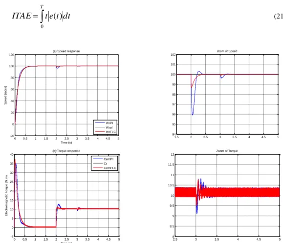
In order to confirmed the robustness for parameters variations we carried out a test for a variation of 50% in the value of star resistance (1.5*RS1 and 1.5*RS2) for the period of the interval] 3-5] s .The speed is fixed at 100 rad/s and a resistant torque of 10N.m is applied at t = 2s.
Figure 10 shows the final test concerns a presents the behavior of FLC and PI speed control when the parameter variations (star resistance), the change in the star resistance is realized as follows: (]3-5] s 1.5*RS1 and 1.5*RS2), Influence of the parameter variations on the electromagnetic torque and speed response is shown in Figure 10 (a), (b).
The PI and a FLC controller is tuned at rated conditions in order to make a fair comparison between the speed control of the DSIM-DTC by a PI and a FLC is presented in all Figures.
In the present study are utilized to judge the performance of the controllers. ISE, IAE and ITAE criterion is widely adopted to evaluate the dynamic performance of the control system.
The index ISE, IAE and ITAE is expressed as follows [18]:
t
dt
e
ISE
T
0 2
(19)
dt
t
e
IAE
T
0
)
(
(20)0 0.5 1 1.5 2 2.5 3 3.5 4 4.5 5 -20
0 20 40 60 80 100 120
Time (s)
S
p
e
e
d
(
ra
d
/s
)
(a):Speed response
WrPI Wref WrFLC
1.5 2 2.5 3 3.5 4 4.5 5 40
50 60 70 80 90 100 110
Zoom of Speed
0 0.5 1 1.5 2 2.5 3 3.5 4 4.5 5 -10
-5 0 5 10 15 20 25 30 35 40
Time (s)
E
le
c
tr
o
m
a
g
n
e
ti
c
t
o
rq
u
e
(
N
.m
)
(b):Torque response
CemPI Cr CemFLC
2.5 3 3.5 4 4.5 5
-10 -5 0 5 10 15 20
dt
t
e
t
ITAE
T
0
)
(
(21)Figure 10. Speed and torque characteristic of an (DTC) with PI and FLC controllers, at parametric variations (star resistance 1.5*RS1 and 1.5*RS2).
ISE: integral squared error, IAE: integral absolute error, ITAE: integral time-weighted absolute error.
For quantitative comparison between two methods, ISE, IAE and ITAE are used as the criterion. Table 3 shows the ISE, IAE and ITAE values of the simulation results of direct torque controle using the PI controller and the proposed FLC Controller (DTC-PI, DTC-FLC in Test1). Actually these performances index are obtained at the end of the simulation time (t=5 sec) with a sampling period h=1*e-5.
This comparison shows clearly that the FLC gives good performances and it’s more robust than PI. Table 3.Quantitative comparison between the proposed FLC and PI controllers
Controllers Index
PI FLC
ISE Speed 19.37 2.552
Flux 0.00343 0.002256
IAE Speed 3.333 1.072
Flux 0.01864 0.01452
ITAE Speed 3.376 1.153
Flux 0.02749 0.0269
5. CONCLUSION
In this study, the performances of speed FLC and PI controllers for direct Torque control of DSIM are presented, has been described. The system was analyzed and designed. The performances were studied extensively by simulation to validate the theoretical concept .To avoid the complexity of the FLC and the decrease of its precision. The robustness tests show too that the FLC is more robust than the PI controller with the speed and torque and parameter variations. The FLC is a useful tool for replacing the PI in all applications (high power variable-speed multi-phase induction machine drives) requiring a good performance and a great robustness and reach high quality in control of non linear systems.
0 0.5 1 1.5 2 2.5 3 3.5 4 4.5 5 -20
0 20 40 60 80 100 120
Time (s)
S
p
e
e
d
(
ra
d
/s
)
(a):Speed response
WrPI Wref WrFLC
1.5 2 2.5 3 3.5 4 4.5 5 94
95 96 97 98 99 100 101 102
Zoom of Speed
0 0.5 1 1.5 2 2.5 3 3.5 4 4.5 5 -5
0 5 10 15 20 25 30 35 40
Time (s)
E
le
c
tr
o
m
a
g
n
e
ti
c
t
o
rq
u
e
(
N
.m
)
(b):Torque response
CemPI Cr CemFLC
2.5 3 3.5 4 4.5 5
8 8.5 9 9.5 10 10.5 11 11.5 12
The simulation study indicates clearly the superior performance of FLC, the comparison done in this work shows that the limits of this type of PI controller can have negative effects on the performance of the DSIM.
REFERENCES
[1] Hadiouche D, Razik H, Rezzoug A. On the Modeling and Design of Dual Stator Windings to Minimize Circulating
Harmonic Currents for VSI Fed AC Machine. IEEE Transactions on Industry Applications. 2004; 40(2): 506-515.
[2] Monti A, Morando A P, Resta I, Riva M. Comparing two level GTO inverter feeding a double star asynchronous
motor with a three level GTO-inverter feeding a single star asynchronous motor. Proceedings of EPE’1995, 1995; 2:
419-425.
[3] Takahashi I, Noguchi T. A new quick response and high efficiency control strategy of induction motor. IEEE Trans.
Ind. Electronics. 1986: 22.
[4] Takahashi I, Asakawa S. Ultra-wide speed control of induction motor covered 10A6 range. IEEE Trans. Ind. Applicat.
1987; 25: 227-232.
[5] Habetler T G, Divan D M. Control strategies for direct torque control using discrete pulse modulation. IEEE Trans.
Ind. Applicat. 1991; 27(5): 893-901.
[6] Amimeur H, Abdessemed R, Aouzellag D, Merabet E, Hamoudi F. Modeling and analysis of dual-stator windings
self-excited induction generator. Journal of Electrical Engineering, JEE. 2008; 8(3): Art. 3,
[7] Ghalem B, Bendiabdellah A. Six-Phase Matrix Converter Fed Double Star Induction Motor. Acta Polytechnica
Hungarica. 2010; 7(3).
[8] Radhwane S. Indirect Rotor Field-oriented Control (IRFOC) of a Dual Star Induction Machine (DSIM) Using a Fuzzy
Controller. Acta Polytechnica Hungarica. 2012; 9(4).
[9] Hadiouche D, Razik H, Rezzoug A. Modeling of a double star-induction motor with an arbitrary shift angle between
its three windings. Proc. EPEPEMC’2000, Kosice, Solvak Republic.2000; 5: 125-130.
[10] Casdei D, Serra G, Tani A. The use of converters in direct control of induction machines. IEEE Trans, on Industrial
Electronics. 2001; 48(6).
[11] La K K, Schin M H, Hyun D S. Direct torque control of induction motor with reduction of torque ripple. IEEE Trans
ind. 2000; 1087-1092.
[12] Hamdy Mohamed Soliman. Performance Characteristics of Induction Motor with Field Oriented Control Compared
to Direct Torque Control. Interantional Journal of Power Electronics and Drive System. 2016; 7(4): 1125-1133.
[13] Muhd Z R Z A, Auzani J, Maaspaliza A, Khairi R. Improved Torque Control Performance in Direct Torque Control
using Optimal Switching Vectors. Interantional Journal of Power Electronics and Drive System. 2015; 5(3):
441-452.
[14] Zaimeddine R, Berkouk E M. A Novel DTC Sheme of Double-star nduction motors using Three-level Voltage source
inverter. Journal of Engineering and applied Sciences.2007; 2(1):136-142.
[15] Sudheer H, Kodad SF, Sarvesh B. Improved Sensorless Direct Torque Control of Induction Motor Using Fuzzy Logic
and Neural Network Based Duty Ratio Controller. Interantional Journal of Power Electronics and Drive System.
2017; 6(2): 79-90.
[16]Belhamdi, S, Golea, A "Direct Field-Oriented Control Using Fuzzy Logic Type -2 for Induction Motor with Broken
Rotor Bars ". IAES International Journal of Artificial Intelligence (IJ-AI) Vol. 4, No. 1, pp. 29~36 March 2015.
[17]Aissaoui A, Abid M, Abid H, Tahour A, Zeblah A. A Fuzzy Logic Controller for Synchronous Machine. Journal of
Electrical Engineering.2007; 58(5): 285-290.
[18]Castillo O, Melin P A. Type-2 fuzzy logic, Theory and applications. Springer-Verlag, Berlin, Germany, 2008; 223.
[19]Hadiouche D. Contribution à l’étude de la machine asynchrone double étoile modélisation, Alimentation et structure.
Thèse de doctorat, Université Henri Poincaré, Nancy-1, 2001.
[20]Abdelfatah N, Abdeldjabar H, Ismail K B. Fuzzy Logic Speed Control Stability Improvement of Lightweight Electric
Vehicle Drive. Journal of Electrical Engineering & Technology. 2010:129–13.
BIOGRAPHIES OF AUTHORS
Hellali Lallouani was born in Bordj Bou Arréridj, Algeria on January 12, 1987. He received the Engineer degree from the University of M'sila, Algeria in 2010 and the M.S degrees in Electrical engineering option electrical industrial from the University of Batna. Algeria in 2016. He is the member of the Research Laboratory Electromagnetic Induction of M’sila Algeria. His main research interests are control system to drive Machines and fault detection in Electric Drives.
Belhamdi Saad was born in M'sila. Algeria in 1976, in 2002 received the Engineer degree from the University of Biskra. Algeria, and in 2005 received the M.S degrees in Electrical engineering option electrical industrial, In 2014 received the PhD, permanent teacher from December 2008 in M'sila University. His main research interests include electrical drives modeling simulation and control He is the member of the Research Laboratory Electromagnetic Induction of M'sila Algeria.
APPENDIX
Table 4. DSIM parameters [8]
DSIM Mechanical Power 4.5 kW
Nominal voltage 220 V
Frequency 50 Hz
Pole pair number 1
Stators 1,2 resistances 3.72 Ω
Rotor resistance 2.12 Ω
Stators 1,2 self inductances 0.022 H
Rotor inductance 0.006 H
Mutual inductance 0.3672 H
Moment of inertia 0.0625Nms2/rad
Friction coefficient 0.001Nms/rad
List of abbreviations and symbols:
Designation Abbreviations
Doubly Star Induction Motor DSIM
Direct Torque Control DTC
Proportional and Integral PI
Fuzzy Logic Controller FLC
Voltage Source Inverter VSI
the rotor angular speed Ωr
Electromagnetic torque Cem
Friction coefficient Kf
Moment of inertia J
Load torque Cr
Angle between stator and rotor flux θs
![Figure 8. DTC of DSIM with load torque (10N.m) between] 2 -3.5] s](https://thumb-us.123doks.com/thumbv2/123dok_us/8384898.2227816/8.892.155.749.98.970/figure-dtc-dsim-load-torque-n-m-s.webp)
![Table 4. DSIM parameters [8]](https://thumb-us.123doks.com/thumbv2/123dok_us/8384898.2227816/12.892.219.698.321.491/table-dsim-parameters.webp)
