Parametric Study of Hot Rolling
Process by the Finite Element Method
A.R. Shahani
1;, S.A. Nodamaie
1and I. Salehinia
1Abstract. In the present investigation, a hot rolling process of AA5083 aluminum alloy is simulated. The approach is based on the thermo-mechanical analysis of the problem using the Finite Element Method (FEM). The temperature distribution in the roll and the slab, the stress, strain and strain rate elds, are extracted throughout a transient analysis of the process. The main hypotheses adopted in the formulation are: The thermo-viscoplastic behavior of the material, expressed by the Perzyna constitutive equation and rolling under plane-deformation conditions. The main variables that characterize the rolling process, such as the geometry of the slab, load, rolling speed, percentage of thickness reduction, initial thickness of the slab and friction coecient, have been expressed in a parametric form, giving good exibility to the model. The congruence of the results has been evaluated using experimental and theoretical data available in the literature.
Keywords: Hot rolling process; Plane strain deformation; Sequential coupling; Contact pressure; Eective stress eld; Temperature distribution.
INTRODUCTION
The rolling process is one of the most popular pro-cesses in manufacturing industries, such that almost 80 percent of metallic equipment has been exposed to rolling at least one time in their production period. Among all kinds of rolling processes, at rolling is the most practical. In industrial countries, about 40-60 percent of rolling products are produced with this type of rolling. Therefore, many scientists have tried to enhance the quality and quantity of prod-ucts by optimizing this process and by identifying parameters aecting it, in order to satisfy their cus-tomers.
Throughout this century, the rolling process has been analyzed by various analytical and numerical methods such as the slab method, the slip-line eld method, the upper bound method, the boundary ele-ment method and the nite eleele-ment method.
In comparison with other methods for analyzing the rolling process, the nite element method is the most practical and accurate. Many models developed
1. Department of Applied Mechanics, Faculty of Mechanical Engineering, K.N. Toosi University of Technology, Tehran, P.O. Box 19395-1999, Iran.
*. Corresponding author. E-mail: [email protected]
Received 13 December 2006; received in revised form 5 August 2007; accepted 26 August 2007
using the FEM have been proposed, diering with respect to:
(i) The type of analysis (transient, steady-state); (ii) The type of formulation (incremental, variational
or ow);
(iii) The solution technique (updated Lagrangian, Eu-lerian);
(iv) The constitutive law hypothesised for the mate-rial behaviour (elasto-plastic, elasto-viscoplastic, rigid-plastic, viscoplastic, etc);
(v) The type of discretization (2-D in the case of plane deformation, 3-D in the case of form rolling); (vi) The type of analysis (mechanical, thermal,
uncou-pled or couuncou-pled thermo-mechanical) [1].
For example, Mori et al. [2] have developed a nite element method using the assumptions of rigid-plastic and slightly compressible material to predict the velocity eld during isothermal steady and unsteady plane strain rolling conditions. Hwu and Lenard [3] have used a nite element method formulation for at rolling processes to assess the eects of work-roll de-formation and various friction conditions on the strain eld. Yarita et al. [4] have analyzed the plane strain rolling process utilizing an elastic-plastic nite element model. They have attempted to predict the stress and
strain distribution within the deformation zone using an updated Lagrangian code. Hwnag et al. [5,6] have assessed the hot strip rolling process. The temperature distributions in rolled metal and in the work-roll and strain eld have been determined in their work. There are also many studies concentrating on evaluating the temperature eld during the hot rolling process [7-12]. For example, Hollander [7] has used a one-dimensional FDM model and the assumption of homogenous de-formation to estimate temperature distribution during hot strip rolling. Devadas and Samarasekara [8] have predicted temperature distribution in hot strip rolled metal, as well as in the work roll. In their work, the eects of process parameters on the temperature eld have been evaluated. Chen et al. [9] calculated the temperature and strain elds by a coupled FEM and FDM code. The kinetic of iron oxidation during hot rolling has also been investigated in their paper. The temperature variations in work-rolls have been considered in a few papers [11,12]. Sluzalec [11] has utilized a two-dimensional nite element method to predict temperature distribution during hot rolling and Teseng et al. [12] have estimated temperature varia-tions in the work-roll, in order to evaluate the thermal stress distribution in the rolls. Duan and Sheppard [13] investigated the inuence of the constitutive equation on FE modeling of the hot rolling of aluminum alloy. Serajzedeh et al. [14] investigated strain inhomogeneity in hot strip rolling using a two-dimensional unsteady-state nite element method.
The contact problem has not been much con-sidered in past literature. However, because of its nonlinear nature and its complex condition, it is very important to consider it particularly. Combining the nite element and boundary element methods, Shangwu et al. [15] carried out 3-D modeling of the hot rolling process of at strips. They predicted rolling force, rolling torque and contact pressure on the roll for both rigid and exible roll cases. Arif et al. [16] simulated roll and strip interaction for a cold rolling process. The main object of this study is to predict roll stresses and deformation behavior by considering both mechanical and thermal loads. Studying the inuence of the number of elements on the tangential and normal components of contact stresses, they showed that the contact stresses are very sensitive to the number of contact elements. Duan and Sheppard [17] besides studying the eect of three friction models considered the contact pressure distribution. They concluded that contact pressure distribution, as a convergence criterion, is greatly sensitive to the number of elements. Phaniraj et al. [18] compared the contact pressure of the roll surface for ve rolling stands of a steel strip. Dvorkin et al. [19,20] did research on the inuence of parameters, such as the coecient of friction and temperature on the distribution of contact stresses.
In the present paper, the hot rolling process of a strip is simulated using the FE standard code, ANSYS 10.0. The roll is assumed to be rigid and, for the deformable aluminum strip, thermo-viscoplastic analysis through 2-D sequential transient thermal and steady-state structural analyses is carried out. This way, the eect of dierent process parameters, such as the initial thickness of the strip, rolling speed and thickness reduction, are studied. On the other hand, the eect of the friction coecient on the contact pressure distribution is investigated.
MATHEMATHICAL MODELING Finite Element Modeling
A 2-D rolling model has been developed to simulate a single pass of the hot rolling process for aluminum alloys using the commercial nite element software package, ANSYS 10.0. An updated Lagrangian method has been employed as a formulation technique through-out use of the software.
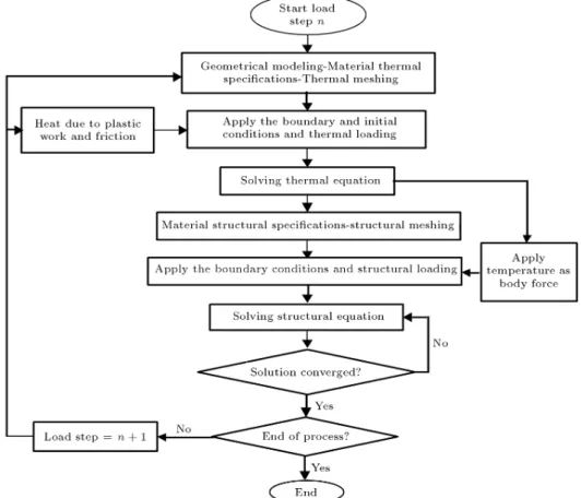
The procedure for an FEM analysis of this process could be formulated in an indirect or direct way. In the indirect or uncoupled approach, the mechanical phenomenon and the thermal phenomenon are corre-lated in sequence, i.e. by applying the results of the thermal model as the body force for the mechanical model [21,22]. The model proposed in this work follows this approach according to the matrix equation [23]:
0 0
0 [Ct] f _T gf _ug
+
[K] 0
0 [Kt] fT gfug
= fF g fQg ; (1) where f _T g is the vector of the temperature rate, fT g is the vector of the temperatures, fF g is the vector of structural load, fQg is the vector of the total heat ow (given by the sum of the contributions due to convection, to the surface loads and to the heat generated internally), f _ug is the vector of the velocity, fug is the vector of the displacements, [K] is the stiness matrix and [Kt] and [Ct] are the total
conductivity and the specic heat matrix, respectively. During the rolling process, the temperature distri-bution in the strip and the work roll can be calculated using the governing partial dierential equation shown in the following equation:
kr2T + _q = c@T
@t; (2)
where (in kgm 3) is the density, c (in Jkg 1C 1)
is the specic heat, k (in Wm 1C 1) is the thermal
conductivity and _q (in Wm 3) is a heat generation term
representing the heat released due to plastic work. It has been established that the temperature distributions in the rolled metal are aected by heat generation, due
to the plastic deformation and friction at the work-roll/strip interface [24]. In order to consider these eects, the heat of plastic deformation is determined by Equation 3.
_q = _"; (3)
where (in MPa) is the eective ow stress, _"(in s 1)
is the eective strain rate and is the eciency of conversion of deformation energy to heat.
A distributed surface ux, qfric, is also generated
from frictional sliding and rises rapidly near the entry and exit regions along the arc of contact, inducing a dramatic change in the relative slip [22]. Its overall contribution to thermal balance in the hot rolling process is low, but if it is considered, its value is determined as below [10]:
qfric= jvj ; (4)
where (in MPa) is the shear stress and v (in mms 1)
is the sliding velocity.
Figure 1 shows the sequential solution of the thermal and structural elds and the transition of data between the two analyses.
The work roll geometry is limited to a 90section,
with a thickness of 10 mm and diameter of 300 mm.
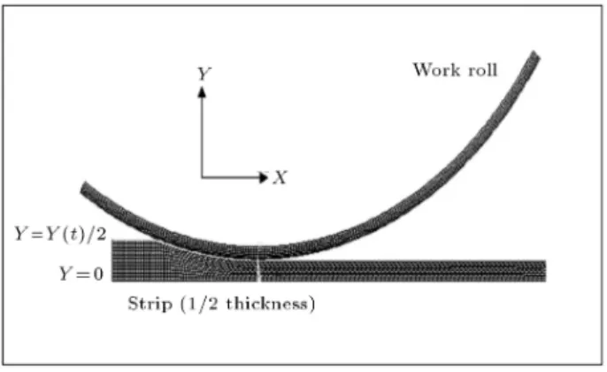
Four node thermal elements, PLANE55, were employed on the thermal and structural analyses. The strip is discretized using four node plane strain elements, PLANE182, which is able to consider large deforma-tion. The work roll is assumed to be a rigid material in the structural analysis. A sensitivity analysis was employed to determine the eect of changing mesh den-sity on the predicted model results. The convergence criterion is the distribution of contact pressure on the contact length. The geometry of the sheet and the work roll are shown in Figure 2.
The contact at the roll-plate interface has been modeled using 2-D contact elements.
Contact happens when a node of the contact surface (node of contact) penetrates the target surface, passing beyond the external circumference of the roll. The contact is described, specifying the normal contact stiness, KN, the coecient of friction, , at the
roll-plate interface and the thermal contact conductance, TCC. In particular, KN is the contact stiness that
acts in a normal direction on the target surface and enforces the displacement compatibility by limiting the penetration of the target base. The thermal contact conductance, TCC, allows consideration of the imperfect contact and the temperature discontinuity across the contact interface.
Figure 2. Geometry of the hot rolling model.
The augmented Lagrangian method was used as a contact algorithm in the simulation. The contact tractions (pressure and frictional stresses) are aug-mented during equilibrium iterations, so that the nal penetration is smaller than the allowable tolerance (TOLN). Compared to the penalty method, the aug-mented Lagrangian method usually leads to better conditioning and is less sensitive to the magnitude of the contact stiness. The contact pressure is dened by:
p = (
0 if un > 0
KNun+ i+1 if un 0 (5)
where: i+1=
(
i+ KNun if junj > "
i if junj < " (6)
" is compatibility tolerance (known as TOLN on soft-ware) and i is the Lagrange multiplier component at
iteration i. The Lagrange multiplier component, i, is
computed locally (for each element) and iteratively. Thermal Boundary Condition
Thermal boundary conditions for the rolling model are needed to describe the heat transfer conditions at the strip centerline at 10 mm from the surface of the work roll and at the contact interface between the strip and work roll. Referring to Figure 1, the boundary conditions in the model are dened as follows:
(i) At the centerline of the strip, symmetry condition is assumed:
kstrip@T@y = 0 at t > 0; y = 0: (7)
(ii) At a distance of 10 mm below the work roll surface an adiabatic condition is assumed:
kroll@T@r = 0 at t > 0; r = r10mm: (8)
(iii) At the contact interface between the strip and the work roll, an interfacial heat transfer coecient is assumed:
qstrip= qroll= h(Tstrip Troll);
at t > 0; y = Y (t)2 ; or r = R; (9) where R is the outer radius of roll.
The interfacial heat transfer coecient, h, is set to 25 kWm 2K 1 and the heat transfer coecient
between the work piece and the air is set to 0.01 kWm 2 K 1[13].
Mechanical Boundary Condition
A contact boundary condition describing the mechan-ical interaction of the strip and the roll was imposed along the strip/roll interface. Interfacial friction for the contact area is proportional to normal force, as shown in Equation 10.
crit= P; (10)
where crit (in Pa) is the critical shear stress, is the
coecient of friction and P is contact pressure. A baseline coecient of friction of 0.5 is used. In the basic Coulomb friction model, two contacting surfaces can carry shear stresses up to a certain magnitude (crit)
across their interface before they start sliding relative to each other. The state is known as sticking. Once the equivalent shear stress exceeds crit, the contact
and target surfaces will slide relative to each other. This state is known as sliding. The sticking/sliding calculations are determined when a transition from sticking to sliding or vice versa is occurred.
Deformation symmetry in the strip is maintained through a zero displacement boundary condition in the through thickness direction along the strip centerline. This allows a reduction in geometric complexity and reduces computational time.
Rolling speed is introduced in the model by applying a rotational velocity to a pilot node lying at the centre of the roll.
Material Properties
The strip is assumed to behave as a thermo-elastoviscoplastic material with a temperature inde-pendent elastic modulus of 70 GPa and a Poisson ratio of 0.33. The range of temperatures, strains and strain rates experienced by the material during the rolling process is large. Also, according to Equation 3, during the rolling process, the plastic work causes heat generation in the slab, which is proportional to the strain rate. Hence, it is necessary to dene the strip's
plastic behavior as a function of temperature, strain and strain rate. This can be done using the Perzyna equation [23]:
= "
1 +
_"pl
(T )
m(T )#
0("pl; T ): (11)
In this equation, is the yield stress, expressed as a function of plastic strain rate, _"pl, material viscosity
parameter, , strain rate hardening parameter, m, and the static subsequent yield stress, 0.
By tting the Perzyna equation on the experimen-tal data, parameters m and are determined.
To nd the constants of the Perzyna equation, the curve of Equation 9 has been tted to the exper-imental data. The constants of the Perzyna equation for AA5083 are summarized in Table 1 for dierent temperatures [13].
The thermophysical properties of AA5083 are shown in Table 2 [25]. The density of the strip was assumed to be constant at 2660 kgm 3 [26].
By considering the thermophysical properties of the strip to be temperature dependent, the thermal equation follows a nonlinear form; hence, the temper-ature of the previous load step has been applied to the thermophysical properties and, consequently, the thermal equation has been solved.
The thermophysical properties of the work roll are shown in Table 3.
RESULTS AND DISCUSSION Verication of the Results
The model developed in this investigation is validated by comparing the model predictions of the rolling force, temperatures and strains with the experimental and theoretical results of Duan and Sheppard [13].
Table 1. Summary of Perzyna constant. T 283C 350C 450C
m 0.18 0.17 0.168 0.05 0.04 0.04
Table 2. Thermophysical properties of AA5083 [25]. Temperature
(C)
Heat Capacity (Jkg 1K 1)
Thermal Coductivity (Wm 1K 1)
14 930 143.4 280 990 167.1 306 1010 170.2 410 1050 174.1 505 1160 185.4
Table 3. Thermophysical properties of the work roll [25]. Heat Capacity
(Jkg 1K 1)
Thermal Conductivity (Wm 1K 1)
Density (kgm 3)
460 14 7800
They simulated the process with an assumption of the thermo-viscoplastic behavior of material. The rolling pass schedules on their modeling included an entry thickness of 50 mm, a thickness reduction of 5.74%, a rolling temperature of 283 centigrade and a roll radius of 460 mm.
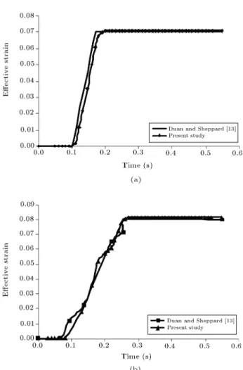
The thermal stress analysis in this problem is accomplished in two dierent ways: In the rst, it is assumed that the temperature change in the slab is not signicant and the temperature can be assumed to be constant (isothermal viscoplastic modeling). The second method is based on the analysis of temperature changes in the slab and work roll, followed by a structural analysis for nding the stresses (thermo-viscoplastic modeling). The rolling force obtained by thermo-viscoplastic modeling, isothermal-viscoplastic simulation and the average of experimental rolling force versus time, are shown in Figure 3. It can be seen from this gure that the best agreement, with respect to the experimental results, corresponds to the thermoviscoplastic modeling done by Duan and Sheppard [13]. It can also be seen that the isothermal-viscoplastic modeling underestimates the rolling force. Computed at the center of the strip, the temper-ature histories of the present study and the research done by Duan and Sheppard [13] are shown in Figure 4. Paying attention to this gure, it is clear that the temperature at the center of the strip increases with time until it reaches its maximum. This is because of heat generation due to the rate of plastic deformation. Figure 5 presents the eective strain history of the center and the sub-surface point of the strip. It can be seen that the sub-surface point strain is more than at
Figure 3. Comparison of the histories for rolling force per unit width.
Figure 4. History of center point temperature.
Figure 5. Strain histories of rolling pass at the (a) Center point, and (b) Sub-surface point.
the center point, which is attributed to the shear strain at the sub-surface of the strip.
Contact Pressure
For at plate rolling, Li and Kobayashi [26] dened the parameter:
H = tR
in
tin tout
tin
; (12)
where R is the roll radius and tinand toutare the input
and output thickness of the strip, respectively. They concluded that:
(i) H < 3 indicates a double peak contact pressure distribution;
(ii) H > 3 indicates a friction-hill type [27] contact pressure distribution.
They also indicated that the deformation was more homogeneous for the latter case.
For a case in which H = 3, the problem is analyzed for three values of the friction coecient, . In Figure 6a the predicted pressure distribution is plotted. It can be seen from this gure that, as predicted by Li and Kobayashi, there is just one peak or friction hill type [19,20], but the condition, = 0:3, has a dierent shape in comparison with other friction coecients. This can be explained in such a way that a lower friction coecient increases the sliding of the strip in the deformation zone and, consequently, an
Figure 6. Distribution of contact component for various friction coecients. (a) Normal contact stress; (b) Shear contact stress. Initial thickness of 10 mm, rolling speed of 10 rpm, initial temperature of 450C, and Reduction of
increase in the bulk of the material at the inlet of this region increases the contact pressure. In Figure 6b, the predicted shear stresses in the plate/roll interface are plotted. In this case, the position of the non-slip point is less sensitive to changes in the friction coecient [19,20].
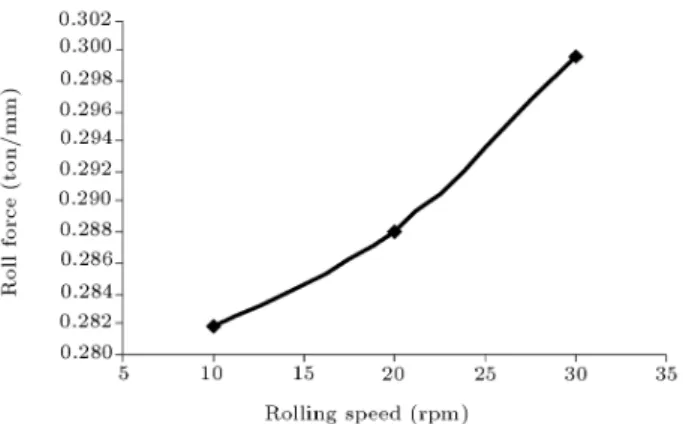
Figure 7 shows the eect of rolling speed on roll force. It is seen that increasing the rolling speed in-creases the roll force. The rolling speed, i.e. the loading rate, has a major eect on the strain rate. According to the constitutive equation, increasing the strain rate results in hardening that causes the material to be more resistant to deformation. In addition, increasing the strain rate enhances internal heat generation, which results in a softening of the material. However, the increase in contact pressure shows that the eect of hardening is dominant.
Eective Stress
According to the constitutive equation, the parameters aecting stress are strain, strain rate and temperature. The distribution of these parameters and also the ma-terial sensitivity to them, can aect stress distribution in the deformation region.
Figure 8 shows the temperature distribution in the deformation zone of the strip. It is observed from Figure 8 that the minimum temperature of the strip occurs at the exit of the deformation zone under the roll, because this point is in contact with the roll in the deformation zone for more time. Figure 9, on the other hand, shows that the maximum strain rate happens at the entry to the deformation zone under the roll, because the deformation in this region occurs suddenly. Therefore, maximum eective stress will occur in one of these two places. With the specied conditions in Figure 10a, it can be seen that maximum eective stress occurs under the roll and at the exit of the deformation region, which has the least
Figure 7. Roll force versus rolling speed. Initial thickness of 10 mm, initial temperature of 450C, and reduction of
20%.
Figure 8. Strip temperature contour during hot
deformation. Initial thickness of 10 mm, rolling speed of 10 rpm, initial temperature of 450C, and reduction of 20%.
Figure 9. Strain rate contour in the deformation zone. Initial thickness of 10 mm, rolling speed of 10 rpm, initial temperature of 450C, and reduction of 20%.
temperature. The preceding remark proves that the eect of temperature is dominant.
Rolling speed is an important parameter during hot strip rolling, since this factor directly controls the strain rate, ow stress, roll force, heat of deformation and the interface heat transfer coecient.
Figure 10b shows that increasing the rolling speed from 10 rpm to 30 rpm causes the point having the maximum stress to get closer to the maximum strain rate point.
Increasing the rolling speed causes the strip and the roll to be in contact for less time. As a result, it decreases the heat ow from the strip to the roll. In addition, if the rolling speed increases, the strain rate will increase as well. Because of increase in the strain rate, the internal heat generation rate enhances. By paying attention to Figure 10b and the preceding remarks, it can be concluded that the eect of the strain rate is predominant in this case.
Temperature
The temperature of the strip, during the rolling pro-cess, depends on several parameters, such as interface
Figure 10. Distribution of eective stress in the deformation zone. Initial thickness of 10 mm, initial temperature of 450C, and reduction of 20%. (a) R.S.: 10
rpm and (b) R.S.: 30 rpm
heat transfer coecient, rolling speed and the amount of thickness reduction at each rolling pass.
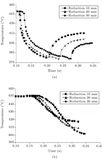
The temperature history of the strip surface for dierent thickness reductions are shown in Figure 11a. The temperature distribution of the strip center versus the time is also shown in Figure 11b. From these gures, it can be seen that the minimum temperature of the surface and the maximum temperature of the center do not vary largely in all of the reductions. It can be explained that more reduction results in longer contact length, which increases heat ow from the strip to the roll. On the other hand, high reduction in constant rolling speed can result in more strain and strain rate in the deformation region together with more internal heat generation, due to the rate of the plastic work. Considering the preceding remarks, we can conclude that with this reduction the maximum temperature of the strip center and the minimum temperature of the strip surface are not very much inuenced by reduction. However, for other geometries (for example initial thickness of 20 mm as shown in Figure 12), the eect of the plastic work due to the higher reduction on the temperature peak is greater.
Figure 11. Temperature history of the strip at the (a) surface and (b) center point. Initial thickness of 10 mm, initial temperature of 450C, and rolling speed of 10 rpm.
Figure 12. Temperature history of the strip at the center point. Initial thickness of 20 mm, initial temperature of 450C, and rolling speed of 10 rpm.
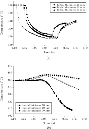
Figure 13 shows the temperature history of the surface point and the centerline of the strip for dierent initial thicknesses. It is seen that, as the initial thickness of the strip increases, the minimum surface temperature decreased. This is also because of an increase in the contact length of the two bodies, which was scrutinized in the preceding paragraph.
Figure 13. Temperature history of the strip at the (a) surface and (b) center point. Initial temperature of 450C,
reduction of 20%, and rolling speed of 10 rpm.
Another investigation can be made by comparing the maximum temperature of the strip center at various initial thicknesses. For similar reduction and rolling speed, the strip with more thickness has a higher temperature at the center, because more thickness increases the distance between the strip center and the strip surface from where the heat exits, so more thickness increases the thermal potential of the strip according to the following equation:
Q = V cT; (13)
where (in kgm 3) is the density, c (in Jkg 1C 1)
is the specic heat, V is the volume and T is the temperature dierence between the strip and the sur-rounding air. Hence, the temperature reaches higher values during deformation.
CONCLUSIONS
The FEM simulation model proposed for the thermo-mechanical analysis of the hot rolling process is able to estimate the eect of process parameters on the thermal and structural behavior of the roll and the
plate, providing good agreement with reported results of experimental and theoretical analyses available in the literature. Noting the results of the FEM simula-tion, the following conclusions can be drawn:
1. Thermal diusion at the roll-plate interface in the deformation zone has major eects on the simula-tion results;
2. The friction coecient aects the components of the contact stress. Deformation homogeneity de-pends on the shape of the contact pressure distri-bution in the deformation zone;
3. The magnitude of the rolling speed aects stress distribution and determines the location of maxi-mum eective stress;
4. The temperature at the center and surface of the strip at various thickness reductions, changes slightly;
5. The amount of initial thickness is another pa-rameter which controls the temperature history. By increasing the initial thickness, the minimum temperature of the strip surface decreases and the maximum temperature of the strip center increases. REFERENCES
1. Galantucci, L.M. and Tricarico, L. \Thermo-mechanical simulation of a rolling process with an FEM approach", J. Material Processing Technology, 92-93, pp. 494-501 (1999).
2. Mori, K., Osakada, K. and Oda, T. \Simulation of plane-strain rolling by the rigid-plastic nite element method", Int. J. Mech. Sci., 24, pp. 519-527 (1982). 3. Hwu, Y. and Lenard, J.G. \A nite element study of
at rolling", Trans. ASME, J. Eng. Mater. Technol., 110, pp. 22-26 (1988).
4. Yarita, I., Mallett, R.L. and Lee, E.H. \Stress and deformation analysis of plane strain rolling process", Steel Res., 56, pp. 231-255 (1988).
5. Hwnag, S.M. and Joun, M.S. \Analysis of hot-strip rolling by a penalty rigid-viscoplastic nite element method", Int. J. Mech. Sci., 34, pp. 979-984 (1992). 6. Hwnag, S.M., Joun, M.S. and Kang, Y.H. \Finite
element analysis of temperatures, metal ow, and roll pressure in hot strip rolling", Trans. ASME Ind., 115, pp. 290-298 (1993).
7. Hollander, F. \A model to calculate the complete temperature distribution in steel during hot rolling", J. Iron Steel Inst., 208, pp. 46-74 (1970).
8. Devadas, C. and Samarasekara, I.V. \Heat transfer-during hot rolling of steel strip", Ironmak. Steelmak., 13, pp. 311-321 (1986).
9. Chen, W.C., Samarasekara, I.V., Kumar, A. and Hawbolt, E.B. \Mathematical modelling of heat ow and deformation during rough rolling", Ironmak. Steel-mak., 20, pp. 113-125 (1993).
10. Fletcher, J.D. and Beynon, J.H. \Heat transfer in roll gap in hot strip rolling", Ironmak. Steelmak., 23, pp. 52-57 (1996).
11. Sluzalec Jr., A. \A preliminary analysis of temperature within roll forging dies, using a nite element method", Int. J. Mach. Tool Des. Res., 24, p. 171 (1984). 12. Teseng, A.A., Lin, F.H., Gunderia, A.S. and Ni,
D.S. \Roll cooling and its relationship to roll life", Metallurgical and Materials Trans. A, 20, pp. 2305-2320 (1990).
13. Duan, X. and Sheppard, T. \The inuence of the constitutive equation on the simulation of a hot rolling process", J. Material Processing Technology, 150, pp. 100-106 (2004).
14. Serajzadeh, S., Karimi Taheri, A., Nejati, M., Izadi, J. and Fattahi, M. \An investigation on strain inho-mogeneity in hot strip rolling process", J. Material Processing Technology, 128, pp. 88-99 (2002). 15. Shangwu, X., Rodrigues, J.M.C. and Martins, P.A.F.
\Three-dimensional simulation of at rolling through a combined nite element-boundary element approach", Finite Elements in Analysis and Design, 32, pp. 221-233 (1999).
16. Arif, A.F.M., Khan, O. and Sheikh, A.K. \Roll deformation and stress distribution under thermo-mechanical loading in cold rolling", J. Materials Pro-cessing Technology, 147, pp. 255-267 (2004).
17. Duan, X. and Sheppard, T. \Three dimensional ther-mal mechanical coupled simulation during hot strip rolling of aluminium alloy 3003", J. Mechanical Sci-ences, 44, pp. 2155-2172 (2002).
18. Phaniraj, M.P., Behera, B.B. and Lahiri, A.K. \Thermo-mechanical modeling of two phase rolling and microstructure evolution in the hot strip mill; Part I.
Prediction of rolling loads and nish rolling temper-ature", J. Materials Processing Technology, 170, pp. 323-335 (2005).
19. Dvorkin, E.N., Goldschmit, M.B., Cavaliere, M.A., Amenta, P.M., Marini, O. and Stroppiana, W. \2D nite element parametric studies of at-rolling pro-cess", J. Material Processing Technology, 68, pp. 99-107 (1997).
20. Cavaliere, M.A., Goldschmit, M.B. and Dvorkin, E.N. \Finite element analysis of steel rolling processes", Computers and Structures, 79, pp. 2075-2089 (2001). 21. Zienkiewicz, O.C. and Taylor, R.L., The Finite
Ele-ment Method, McGraw-Hill, New York (1989). 22. Hwang, S.M., Joun, M.S. and Kang, Y.H. \Finite
element analysis of temperatures, metal ow, and roll pressure in hot strip rolling", ASME J. Eng. Industry, 115, pp. 290-298 (1993).
23. \ANSYS user's manual", version 10.0, Swanson Anal-ysis System.
24. Montmitonnet, P. and Bucssla, P. \A review on theo-retical analyses of rolling in Europe", International J. JST (Japan Science and Technology Agency), 31, pp. 525-538 (1991).
25. Ahmed, H., Wells, M.A., Maijer, D.M., Howes, B.J. and van der Winden, M.R. \Modeling of microstruc-ture evolution during hot rolling of AA5083 using an internal state variable approach integrated into an FE model", Materials Science and Engineering A, 390, pp. 278-290 (2005).
26. Li, G. and Kobayashi, S. \Rigid-plastic nite-element analysis of plain strain rolling", J. Eng. Ind., 104, pp. 55-63 (1982).
27. Backofen, W.A., Deformation Processing, Addision-Wesley, Reading, MA (1972).
![Table 3. Thermophysical properties of the work roll [25].](https://thumb-us.123doks.com/thumbv2/123dok_us/8399347.2231664/5.892.454.800.878.1108/table-thermophysical-properties-work-roll.webp)