LMC555
PC
MOUSE
Implementation
Using
COP800
AN-681
National Semiconductor Application Note 681 Alvin Chan June 1990PC
É
MOUSE
Implementation Using
COP800
ABSTRACTThe mouse is a very convenient and popular device used in data entry in desktop computers and workstations. For desktop publishing, CAD, paint or drawing programs, using the mouse is inevitable. This application note will describe how to use the COP822C microcontroller to implement a mouse controller.
INTRODUCTION
Mouse Systems was the first company to introduce a mouse for PCs. Together with Microsoft and Logitech, they are the most popular vendors in the PC mouse market. Most main-stream PC programs that use pointing devices are able to support the communication protocols laid down by Mouse Systems and Microsoft.
A typical mouse consists of a microcontroller and its associ-ated circuitry, which are a few capacitors, resistors and tran-sistors. Accompanying the electronics are the mechanical parts, consisting of buttons, roller ball and two disks with slots. Together they perform several major functions: mo-tion detecmo-tion, host communicamo-tion, power supply, and but-ton status detection.
MOTION DETECTION
Motion detection with a mouse consists of four commonly known mechanisms. They are the mechanical mouse, the opto-mechanical mouse, the optical mouse and the wheel mouse.
The optical mouse differs from the rest as it requires no mechanical parts. It uses a special pad with a reflective sur-face and grid lines. Light emitted from the LEDs at the bot-tom of the mouse is reflected by the surface and movement is detected with photo-transistors.
The mechanical and the opto-mechanical mouse use a roll-er ball. The ball presses against two rollroll-ers which are con-nected to two disks for the encoding of horizontal and verti-cal motion. The mechaniverti-cal mouse has contact points on the disks. As the disks move they touch the contact bars,
which in turn generates signals to the microcontroller. The opto-mechanical mouse uses disks that contain evenly spaced slots. Each disk has a pair of LEDs on one side and a pair of photo-transistors on the other side.
The wheel mouse has the same operation as the mechani-cal mouse except that the ball is eliminated and the rollers are rotated against the outside surface on which the mouse is placed.
HOST COMMUNICATION
Besides having different operating mechanisms, the mouse also has different modes of communication with the host. It can be done through the system bus, the serial port or a special connector. The bus mouse takes up an expansion slot in the PC. The serial mouse uses one of the COM ports. Although the rest of this report will be based on the opto-mechanical mouse using the serial port connection, the same principle applies to the mechanical and the wheel mouse.
MOTION DETECTION FOR THE OPTO-MECHANICAL MOUSE
The mechanical parts of the opto-mechanical mouse actual-ly consist of one roller ball, two rollers connected to the disks and two pieces of plastic with two slots on each one for LED light to pass through. The two slots are cut so that they form a 90 degree phase difference. The LEDs and the photo-transistors are separated by the disks and the plastic. As the disks move, light pulses are received by the photo-transistors. The microcontroller can then use these quadra-ture signals to decode the movement of the mouse. Figure 1a shows the arrangement of the LEDs, disks, plastic and photo-transistors. The shaft connecting the disk and the ball is shown separately onFigure 1b . Figure 2 shows the signals obtained from the photo-transistors when the mouse moves. The signals will not be exactly square waves because of unstable hand movements.
TL/DD/10799 – 1 a TL/DD/10799 – 2 b FIGURE 1 TL/DD/10799 – 3 TL/DD/10799 – 4 Signals at phototransistors are similar for vertical and horizontal motion.
Track 1 leads track 0 by 90 degrees
RESOLUTION, TRACKING SPEED AND BAUD RATE
The resolution of the mouse is defined as the number of movement counts the mouse can provide for each fixed dis-tance travelled. It is dependent on the physical dimension of the ball and the rollers. It can be calculated by measuring the sizes of the mechanical parts.
An example for the calculation can be shown by making the following assumptions:
# The disks have 40 slots and 40 spokes
# Each spoke has two data counts
(This will be explained in the section ‘‘An Algorithm for Detecting Movements’’)
# Each slot also has two data counts
# The roller has a diameter of 5mm
For each revolution of the roller, there will be 40c2c2e
160 counts of data movement. At the same time, the mouse would have travelled a distance of q c 5 e 15.7mm.
Therefore the resolution of the mouse is 15.7/160 e
0.098mm per count. This is equivalent to 259 counts or dots per inch (dpi).
The tracking speed is defined as the fastest speed that the mouse can move without the microcontroller losing track of the movement. This depends on how fast the microcontrol-ler can sample the pulses from the photo-transistors. The effect of a slow tracking speed will contribute to jerking movements of the cursor on the screen.
The baud rate is fixed by the software and the protocol of the mouse type that is being emulated. For mouse systems and microsoft mouse, they are both 1200. Baud rate will affect both the resolution and the tracking speed. The inter-nal movement counter may overflow while the mouse is still sending the last report with a slow baud rate. With a fast baud rate, more reports can be sent for a certain distance moved and the cursor should appear to be smoother.
POWER SUPPLY FOR THE SERIAL MOUSE
Since the serial port of the PC has no power supply lines, the RTS, CTS, DTR and DSR RS232 interface lines are
utilized. Therefore the microcontroller and the mouse hard-ware should have very little power consumption. National Semiconductor’s COP822C fits into this category perfectly. The voltage level in the RS232 lines can be either positive or negative. When they are positive, the power supply can be obtained by clamping down with diodes. When they are negative, a 555 timer is used as an oscillator to transform the voltage level to positive. The 1988 National Semicon-ductor Linear 3 Databook has an example of how to gener-ate a variable duty cycle oscillator using the LMC555 in page 5-282.
While the RTS and DTR lines are used to provide the volt-age for the mouse hardware, the TXD line of the host is utilized as the source for the communication signals. When idle, the TXD line is in the mark state, which is the most negative voltage. A pnp transistor can be used to drive the voltage of the RXD pin to a voltage level that is compatible with the RS232 interface standard.
AN ALGORITHM FOR DETECTING MOVEMENTS
The input signal of the photo-transistors is similar to that shown inFigure 2 . Track 1 leads track 0 by 90 degrees. Movement is recorded as either of the tracks changes state. State tables can be generated for clockwise and counter-clockwise motions.
With the two tracks being 90 degrees out of phase, there could be a total of four possible track states. It can be ob-served that the binary values formed by combining the pres-ent and previous states are unique for clockwise and coun-ter-clockwise motion. A sixteen entry jump table can be formed to increment or decrement the position of the cur-sor. If the value obtained does not correspond to either the clockwise or counter-clockwise movement, it could be treat-ed as noise. In that case either there is noise on the micro-controller input pins or the micromicro-controller is tracking mo-tions faster than the movement of the mouse. A possible algorithm can be generated as follows. The number of in-struction cycles for some inin-structions are shown on the left.
(TRK1, TRK0)t (TRK1, TRK0)tb1 Binary Value (TRK1, TRK0)t (TRK1, TRK0)tb1 Binary Value
CCW CW
0 1 0 0 4 1 0 0 0 8
1 1 0 1 D 0 0 0 1 1
1 0 1 1 B 0 1 1 1 7
CYCLES ;*************************************************** ; SAMPLE SENSOR INPUT
; INC OR DEC THE POSITION
;*************************************************** ; SENSOR: 1 LD B,#GTEMP 3 LD A,PORTGP 1 RRC A 2 AND A,#03C ; G6,G5,G4,G3 1 X A, [B] ; (GTEMP) ; 2 LD A, [B0] ; (GTEMP) X IN 3,2 1 RRC A 1 RRC A 2 AND A, #03 1 OR A, [B] ; (TRACKS) 2 OR A, #0B0 ; X MOVEMENT TABLE 3 JID ; NOISEX: JP YDIR ; 3 INCX: LD A,XINC 1 INC A 3 JP COMX ; DECX: LD A,XINC DEC A COMX: 2 IFEQ A, #080 1 JP YDIR 3 X A, XINC 1 LD B, #CHANGE 1 SBIT RPT, [B] 1 LD B, #TRACKS ; YDIR: 2 LD A, [B1] ; (TRACKS) Y IN 5, 4 1 SWAP A 1 RRC A 1 RRC A 1 RRC A 2 AND A, #0C0 1 OR A, [B] ; (GTEMP)
1 SWAP A 2 OR A, #0C0 ; Y MOVEMENT TABLE 3 JID ; NOISEY: JP ESENS ; 3 INCY: LD A, YINC 1 INC A 3 JP COMY DECY: LD A, YINC DEC A COMY: 2 IFEQ A, #080 1 JP ESENS 3 X A, YINC 1 LD B, #CHANGE 1 SBIT RPT, [B] 1 LD B, #GTEMP ESENS: 2 LD A, [B0] ; (GTEMP) IN5, 4, 1, 0 1 X A, [B] ; (TRACKS) NEW TRACK STATUS
5 RET ; .40B0 MOVEMX: .ADDR NOISEX ; 0 .ADDR INCX ; 1 .ADDR DECX ; 2 .ADDR NOISEX ; 3 .ADDR DECX ; 4 .ADDR NOISEX ; 5 .ADDR NOISEX ; 6 .ADDR INCX ; 7 .ADDR INCX ; 8 .ADDR NOISEX ; 9 .ADDR NOISEX ; A .ADDR DECX ; B .ADDR NOISEX ; C .ADDR DECX ; D .ADDR INCX ; E .ADDR NOISEX ; F ; .40C0 MOVEMY: .ADDR NOISEY ; 0 .ADDR INCY ; 1 .ADDR DECY ; 2 .ADDR NOISEY ; 3 .ADDR DECY ; 4 .ADDR NOISEY ; 5 .ADDR NOISEY ; 6 .ADDR INCY ; 7 .ADDR INCY ; 8 .ADDR NOISEY ; 9 .ADDR NOISEY ; A .ADDR DECY ; B .ADDR NOISEY ; C .ADDR DECY ; D .ADDR INCY ; E .ADDR NOISEY ; F
Going through the longest route in the sensor routine takes 75 instruction cycles. So at 5 MHz the microcontroller can track movement changes within 150ms by using this algo-rithm.
MOUSE PROTOCOLS
Since most programs in the PC support the mouse systems and microsoft mouse, these two protocols will be discussed here. The protocols are byte-oriented and each byte is framed by one start-bit and two stop-bits. The most com-monly used reporting mode is that a report will be sent if there is any change in the status of the position or of the buttons.
MICROSOFT COMPATIBLE DATA FORMAT
Bit
6 5 4 3 2 1 0 Number
1 L R Y7 Y6 X7 X6 Byte 1
0 X5 X4 X3 X2 X1 X0 Byte 2
0 Y5 Y4 Y3 Y2 Y1 Y0 Byte 3
L, ReKey data (Left, Right key) 1ekey depressed
X0–X7eX distance 8-bit two’s complement valueb128 toa127
Y0–Y7eY distance 8-bit two’s complement valueb128 toa127
PositiveeSouth
In the Microsoft Compatible Format, data is transferred in the form of seven-bit bytes. Y movement is positive to the south and negative to the north.
FIVE BYTE PACKED BINARY FORMAT (MOUSE SYSTEMS CORP)
Bit 7 6 5 4 3 2 1 0 Number 1 0 0 0 0 L* M* R* Byte 1 X7 X6 X5 X4 X3 X2 X1 X0 Byte 2 Y7 Y6 Y5 Y4 Y3 Y2 Y1 Y0 Byte 3 X7 X6 X5 X4 X3 X2 X1 X0 Byte 4 Y7 Y6 Y5 Y4 Y3 Y2 Y1 Y0 Byte 5
L*, M*, R*eKey data (Left, Middle, Right key), 0ekey depressed
X0–X7eX distance 8-bit two’s complement valueb127 toa127
Y0–Y7eY distance 8-bit two’s complement valueb127 toa127
In the Five Byte Packed Binary Format data is transferred in the form of eight-bit bytes (eight data bits without parity). Bytes 4 and 5 are the movement of the mouse during the transmission of the first report.
THE COP822C MICROCONTROLLER
The COP822C is an 8-bit microcontroller with 20 pins, of which 16 are I/O pins. The I/O pins are separated into two ports, port L and port G. Port G has built-in Schmitt-trig-gered inputs. There is 1k of ROM and 64 bytes of RAM. In the mouse application, the COP822C’s features used can be summarized below. Port G is used for the photo-transis-tor’s input. Pin G0 is used as the external interrupt input to monitor the RTS signal for the microsoft compatible proto-col. The internal timer can be used for baud rate timing and interrupt generation. The COP822C draws only 4 mA at a crystal frequency of 5 MHz. The instruction cycle time when operating at this frequency is 2ms.
A MOUSE EXAMPLE
The I/O pins for the COP822C are assigned as follows:
Pin Function
G0 Interrupt Input (Monitoring RTS Toggle) G1 Reserved for Input Data (TXD of Host) G2 Output Data (RXD of Host)
G3 – G6 LED Sensor Input L0 – L2 Button Input
L3 Jumper Input (for Default Mouse Mode) The timer is assigned for baud rate generation. It is config-ured in the PWM auto-reload mode (with no G3 toggle out-put) with a value of 1A0 hex in both the timer and the auto-reload register. When operating at 5 MHz, it is equivalent to 833ms or 1200 baud. When the timer counts down, an inter-rupt is generated and the service routine will indicate in a timer status byte that it is time for the next bit. The subrou-tine that handles the transmission will look at this status byte to send the data.
The other interrupt comes from the G0 pin. This is imple-mented to satisfy the microsoft mouse requirement. As the RTS line toggles, it causes the microcontroller to be inter-rupted. The response to the toggling is the transmission of the character ‘‘M’’ to indicate the presence of the mouse. The main program starts by doing some initializations. Then it loops through four subroutines that send the report, sense the movement, sense the buttons, and set up the report format.
Subroutine ‘‘SDATA’’ uses a state table to determine what is to be transmitted. There are 11 or 12 states because microsoft has only 7 data bits and mouse systems has 8. The state table is shown below:
SENDST State
0 IDLE
1 START BIT
2 – 8 DATA (FOR MICROSOFT) 2 – 9 DATA (FOR MOUSE SYSTEMS) 9 – 10 STOP BIT (FOR MICROSOFT) 10 – 11 STOP BIT (FOR MOUSE SYSTEMS) 11 NEXT WORD (FOR MICROSOFT) 12 NEXT WORD (FOR MOUSE SYSTEMS) The G2 pin is set to the level according to the state and the data bit that is transmitted.
Subroutine ‘‘SENSOR’’ checks the input pins connected to the LEDs. The horizontal direction is checked first followed by the vertical direction. Two jump tables are needed to decode the binary value formed by combining the present and previous status of the wheels. The movements are re-corded in two counters.
Subroutines ‘‘BUTUS’’ and ‘‘BUTMS’’ are used for polling the button input. They compare the button input with the value polled last time and set up a flag if the value changes. Two subroutines are used for the ease of setting up reports for different mice. The same applies for subroutines ‘‘SRPTMS’’ and ‘‘SRPTUS’’ which set up the report format for transmission. The status change flag is checked and the report is formatted according to the mouse protocol. The
movement counters are then cleared. Since the sign of the vertical movement of mouse systems and microsoft is re-versed, the counter value in subroutine ‘‘SRPTMS’’ is com-plemented to form the right value.
There is an extra subroutine ‘‘SY2RPT’’ which sets up the last two bytes in the mouse systems’ report. It is called after the first three bytes of the report are sent.
The efficiency of the mouse depends solely on the effec-tiveness of the software to loop through sensing and trans-mission subroutines. For the COP822C, one of the most effective addressing modes is the B register indirect mode.
It uses only one byte and one instruction cycle. With autoin-crement or autodeautoin-crement, it uses one byte and two instruc-tion cycles. In order to utilize this addressing mode more often, the organization of the RAM data has to be carefully thought out. In the mouse example, it can be seen that by placing related variables next to each other, the saving of code and execution time is significant. Also, if the RAM data can fit in the first 16 bytes, the load B immediate instruction is also more efficient. The subroutine ‘‘SRPTMS’’ is shown below and it can be seen that more than half the instruc-tions are B register indirect which are efficient and compact.
;
; VARIABLES ;
WORDPT 4 000 ;WORD POINTER
WORD1 4 001 ;BUFFER TO STORE REPORTS WORD2 4 002
WORD3 4 003
CHANGE 4 004 ;MOVEMENT CHANGE OR BUTTON PRESSED XINC 4 005 ;X DIRECTION COUNTER
YINC 4 006 ;Y DIRECTION COUNTER NUMWORD 4 007 ;NUMER OF BYTES TO SEND SENDST 4 008 ;SERIAL PROTOCOL STATE ;
;****************************************************** ; SUBROUTINE SET UP REPORT ’SRPT’ FOR MOUSE SYSTEMS ; CHANGE OF STATUS DETECTED
; SET UP THE FIRST 3 WORDS FOR REPORTING ; IF IN IDLE STATE
;****************************************************** ;
SRPTMS:
LD A,CHANGE
IFEQ A, #0 ; EXIT IF NO CHANGE RET
;
RBIT GIE, PSW ; DISABLE INTERRUPT LD B, #WORDPT
LD [B0], #01 ; (WORDPT) SET WORD POINTER LD A, BUTSTAT X A, [B0] ; (WORD1) ; LD A, XINC X A, [B0] ; (WORD2) ; SC CLR A
SUBC A, YINC ; FOR MOUSE SYSTEM NEG Y X A, [B0] ; (WORD3)
;
RBIT RPT, [B] ; (CHANGE) RESET CHANGE OF STATUS SBIT SYRPT, [B] ; (CHANGE)
LD A, [B0] ; INC B LD [B0], #0 ; (XINC) LD [B0], #0 ; (YINC) ;
LD [B0], #03 ; (NUMWORD) SEND 3 BYTES
LD [B], #01 ; (SENDST) SET TO START BIT STATE ; SBIT GIE, PSW ; ENABLE INTERRUPT
RET ;
CONCLUSION
The COP822C has been used as a mouse controller. The code presented is a minimum requirement for implementing a mouse systems and microsoft compatible mouse. About 550 bytes of ROM code has been used. The remaining ROM area can be used for internal diagnostics and for com-municating with the host’s mouse driver program. The un-used I/O pins can be un-used to turn the LED’s on only when necessary to save extra power. This report demonstrated the use of the efficient instruction set of the COP800 family. It can be seen that the architecture of the COP822C is most suitable for implementing a mouse controller. The table be-low summarizes the advantages of the COP822C.
Feature Advantage
Port G Schmitt Triggered Input for Photo-Transistors G0 External Interrupt for RTS Toggling Timer For Baud Rate Generation Low Power 4 mA at 5 MHz
Small Size 20-Pin DIP
REFERENCE
The mouse still reigns over data entryÐElectronic Engineer-ing Times, October 1988.
MICE for mainstream applicationsÐPC Magazine, August 1987.
Logimouse C7 Technical Reference ManualÐLogitech, January 1986.
APPENDIX AÐMEMORY UTILIZATION RAM Variables
TEMP e 0F1 Work Space
ASAVE e 0F4 Save A Register
PSSAVE e 0F6 Save PSW Register
WORDPT e 000 Word Pointer
WORD1 e 001 Buffer to Store Report
WORD2 e 002 Buffer
WORD3 e 003 Buffer
CHANGE e 004 Movement or Button Change
XINC e 005 X Direction Counter
YINC e 006 Y Direction Counter
NUMWORD e 007 Number of Bytes to Send
SENDST e 008 Serial Protocol State
TSTATUS e 00A Counter Status
MTYPE e 00B Mouse Type
GTEMP e 00C Track Input from G Port
TRACKS e 00D Previous Track Status
BTEMP e 00E Button Input from L Port
BUTSTAT e 00F Previous Button Status
APPENDIX BÐSUBROUTINE SUMMARY
Subroutine Location Function
MLOOP 03D Main Program Loop SENSOR 077 Sample Photo-Transistor Input INTRP 0FF Interrupt Service Routines SRPTUS 136 Set Up Report for Microsoft
SRPTMS 16C Set Up 1st 3 Bytes Report for Mouse Systems SDATA 191 Drive Data Transmission Pin According to Bit
Value of Report
SY2RPT 1D1 Set Up Last 2 Bytes Report for Mouse Systems BUTUS 200 Sample Button Input for Microsoft
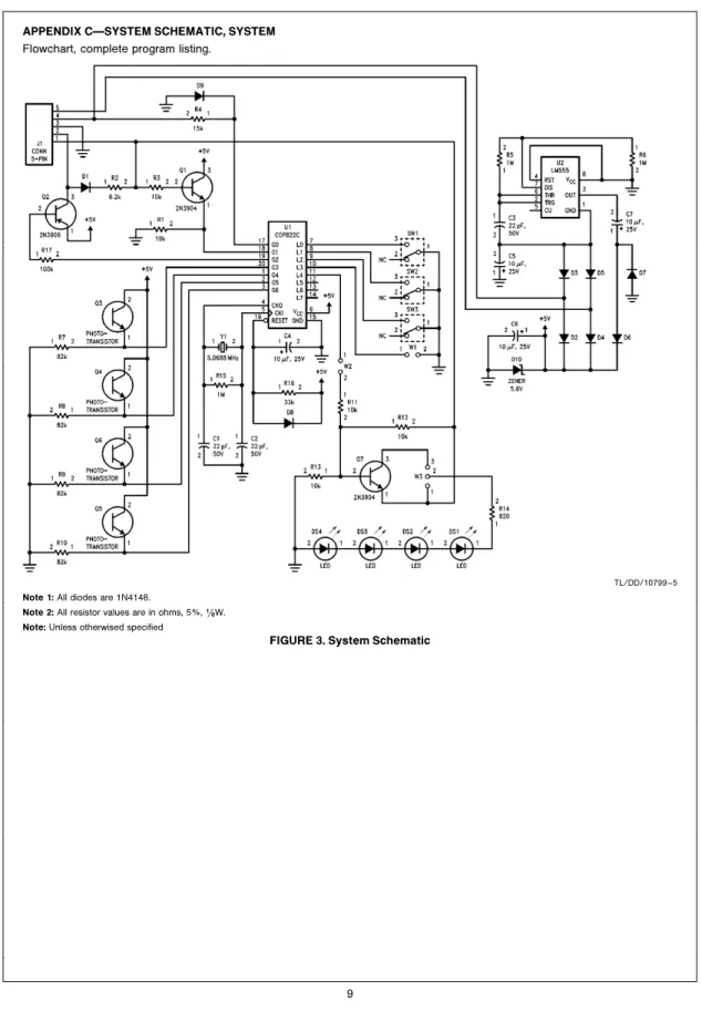
APPENDIX CÐSYSTEM SCHEMATIC, SYSTEM
Flowchart, complete program listing.
TL/DD/10799 – 5
Note 1:All diodes are 1N4148.
Note 2:All resistor values are in ohms, 5%,(/8W.
Note:Unless otherwised specified
Flowchart for Mouse Systems and Microsoft Mouse
TL/DD/10799 – 20
TL/DD/10799 – 22
PC
MOUSE
Implementation
Using
COP800
LIFE SUPPORT POLICY
NATIONAL’S PRODUCTS ARE NOT AUTHORIZED FOR USE AS CRITICAL COMPONENTS IN LIFE SUPPORT DEVICES OR SYSTEMS WITHOUT THE EXPRESS WRITTEN APPROVAL OF THE PRESIDENT OF NATIONAL SEMICONDUCTOR CORPORATION. As used herein:
1. Life support devices or systems are devices or 2. A critical component is any component of a life systems which, (a) are intended for surgical implant support device or system whose failure to perform can into the body, or (b) support or sustain life, and whose be reasonably expected to cause the failure of the life failure to perform, when properly used in accordance support device or system, or to affect its safety or with instructions for use provided in the labeling, can effectiveness.
be reasonably expected to result in a significant injury to the user.
National Semiconductor National Semiconductor National Semiconductor National Semiconductor National Semiconductores National Semiconductor