Important
Read, understand and obey the safety rules and operating instructions in the Genie S-100 and Genie
S-105 Operator's Manual or the Genie S-120 and Genie S-125 Operator's Manual before attempting
any maintenance or repair procedure.
This service manual covers the Genie S-100 and Genie S-105 and Genie S-120 and Genie S-125 models.
This manual provides detailed scheduled maintenance information for the machine owner and user. It also provides troubleshooting and repair procedures for qualified service
professionals.
Basic mechanical, hydraulic and electrical skills are required to perform most procedures. However, several procedures require specialized skills, tools, lifting equipment and a suitable workshop. In these instances, we strongly recommend that
maintenance and repair be performed at a Genie dealer service center.
Genie Industries has endeavored to deliver the highest degree of accuracy possible. However, continuous improvement of our products is a Genie policy. Therefore product specifications are subject to change without notice.
Readers are encouraged to notify Genie of errors and send in suggestions for improvement. All communications will be carefully considered for future printings of this and other manuals. Please write to the technical publications team in care of Genie Industries, PO Box 97030, Redmond WA
Contact us:
http://www.genielift.com e-mail: [email protected]
Safety Rules
Danger
Failure to obey the instructions and safety rules in this manual, and the Genie S-100 & Genie S-105
Operator's Manual or the Genie S-120 & Genie S-125 Operator's Manual will result in death or
serious injury.
Many of the hazards identified in the operator's manual are also safety hazards when maintenance and repair procedures are performed.
Do Not Perform Maintenance
Unless:
You are trained and qualified to perform maintenance on this machine.
You read, understand and obey:
- manufacturer’s instructions and safety rules - employer’s safety rules and worksite
regulations
- applicable governmental regulations You have the appropriate tools, lifting equipment and a suitable workshop.
SAFETY RULES
Workplace Safety
Be sure to keep sparks, flames and lighted tobacco away from flammable and combustible materials like battery gases and engine fuels. Always have an approved fire extinguisher within easy reach.
Be sure that all tools and working areas are properly maintained and ready for use. Keep work surfaces clean and free of debris that could get into machine components and cause damage.
Be sure that your workshop or work area is properly ventilated and well lit.
Be sure any forklift, overhead crane or other lifting or supporting device is fully capable of supporting and stabilizing the weight to be lifted. Use only chains or straps that are in good condition and of ample capacity.
Be sure that fasteners intended for one time use (i.e., cotter pins and self-locking nuts) are not reused. These components may fail if they are used a second time.
Be sure to properly dispose of old oil or other fluids. Use an approved container.
Personal Safety
Any person working on or around a machine must be aware of all known safety hazards. Personal safety and the continued safe operation of the machine should be your top priority.
Read each procedure thoroughly. This manual and the decals, on the machine, use signal words to identify the following:
Indicates the presence of a hazard that will cause death or serious injury. Indicates the presence of a hazard that may cause death or serious injury. Indicates the presence of a hazard that will or may cause serious injury or damage to the machine. Indicates special
operation or maintenance information.
Be sure to wear protective eye wear and other protective clothing if the situation warrants it.
Be aware of potential crushing hazards such as moving parts, free swinging or unsecured components, and lifting or
Table of Contents
Introduction
Important Information ... ii
Section One Safety Rules
General Safety Rules ... iii
Section Two Specifications
Machine Specifications, S120 and S-125 Models ... 2 - 1 Performance Specifications, S120 and S-125 Models ... 2 - 2 Machine Specifications, S100 and S-105 Models ... 2 - 3 Performance Specifications, S100 and S-105 Models ... 2 - 5 Hydraulic Specifications ... 2 - 6 Perkins Engine 1004-42 Specifications ... 2 - 7 Cummins Engine B3.9L Specifications ... 2 - 8 Deutz Engine F4L 913 Specifications ... 2 - 9 Hydraulic Hose and Fitting Torque Specifications ... 2 - 10
Section Three Theory of Operation
Theory of Operation ... 3 - 1
Section Four Scheduled Maintenance Procedures
Introduction ... 4 - 1 Maintenance Inspection Report ... 4 - 3 A-1 Inspect the Manuals ... 4 - 5 A-2 Inspect the Decals and Placards ... 4 - 5 A-3 Inspect for Damage and Loose or Missing Parts ... 4 - 6 A-4 Check the Engine Oil Level ... 4 - 6
TABLE OF CONTENTS
Section Four Scheduled Maintenance Procedures, continued
A-5 Check the Engine Coolant Level - Liquid Cooled Models ... 4 - 7 A-6 Check the Engine Belt(s) - Cummins Models ... 4 - 8 A-7 Check the Engine Cooling Fan - Liquid Cooled Models ... 4 - 9 A-8 Drain the Inline Fuel Filter/Water Separator ... 4 - 10 A-9 Inspect the Engine Air Filter ... 4 - 11 A-10 Check for Fuel Leaks ... 4 - 12 A-11 Check the Hydraulic Oil Level ... 4 - 12 A-12 Check for Hydraulic Leaks ... 4 - 13 A-13 Check the Hydraulic Filter Condition Indicators ... 4 - 13 A-14 Test the Platform and Ground Controls ... 4 - 15 A-15 Test the Auxiliary Power Operation ... 4 - 16 A-16 Test the Tilt Sensor and Alarm ... 4 - 17 A-17 Test the Operating Envelope ... 4 - 18 A-18 Perform 30 Day Service ... 4 - 19 A-19 Check the Engine Fasteners - Deutz Models ... 4 - 20 A-20 Check the Batteries ... 4 - 21 B-1 Check the Radiator - Liquid Cooled Models ... 4 - 23 B-2 Check the Oil Cooler and Cooling Fins - Deutz Models ... 4 - 24 B-3 Check the Engine Belt(s) - Deutz and Perkins Models ... 4 - 25 B-4 Replace the Inline Fuel Filter/Water Separator Element ... 4 - 26 B-5 Replace the Air Filter ... 4 - 32 B-6 Inspect the Air Intake System ... 4 - 33 B-7 Check the Exhaust System ... 4 - 33
TABLE OF CONTENTS
Section Four Scheduled Maintenance Procedures, continued
B-8 Replace the Hydraulic Tank Return Filters ... 4 - 35 B-9 Replace the Hydraulic Tank Breather Filter ... 4 - 36 B10 Replace the Medium and High Pressure Hydraulic Filters ... 4 - 37 B-11 Inspect the Electrical Wiring ... 4 - 38 B-12 Confirm the Proper Brake Configuration ... 4 - 39 B-13 Inspect the Tires and Wheels (including lug nut torque) ... 4 - 39 B-14 Check the Oil Level in the Drive Hubs ... 4 - 40 B-15 Check and Adjust the Engine RPM ... 4 - 41 B-16 Test the Key Switches ... 4 - 44 B-17 Test the Emergency Stop Buttons ... 4 - 46 B-18 Test the Ground Control Override ... 4 - 46 B-19 Test the Safety Envelope and Circuits ... 4 - 47 B-20 Test the Platform Self-leveling ... 4 - 53 B-21 Test the Horn ... 4 - 54 B-22 Test the Foot Switch ... 4 - 54 B-23 Test the Engine Idle Select ... 4 - 55 B-24 Test the Drive Enable System ... 4 - 56 B-25 Test the Drive Brakes ... 4 - 57 B-26 Test the Drive Speed - Stowed Position ... 4 - 58 B-27 Test the Drive Speed - Raised or Extended Position ... 4 - 58 B-28 Test the Alarm Package (if equipped) ... 4 - 60 B-29 Replace the Engine Oil and Filter - Cummins Models ... 4 - 61 B-30 Inspect the Fuel Tank Cap Venting System ... 4 - 62 B-31 Perform Hydraulic Oil Analysis ... 4 - 63
TABLE OF CONTENTS
Section Four Scheduled Maintenance Procedures, continued
C-1 Check the Engine Valve Clearances - Deutz Models ... 4 - 64 C-2 Clean the Fuel Pump Strainer - Perkins Models ... 4 - 64 C-3 Replace the Fuel Filter Element - Perkins and Cummins Models ... 4 - 66 C-4 Replace the Engine Oil and Filter - Deutz and Perkins Models ... 4 - 68 C-5 Check the Specific Gravity of the Coolant - Liquid Cooled Models ... 4 - 70 C-6 Inspect the Boom Extend/Retract Cables ... 4 - 71 D-1 Check the Boom Wear Pads ... 4 - 73 D-2 Check the Extendable Axle Wear Pads ... 4 - 74 D-3 Check the Free-wheel Configuration ... 4 - 75 D-4 Check the Turntable Rotation Bearing Bolts ... 4 - 76 D-5 Check the Turntable Rotation Gear Backlash ... 4 - 77 D-6 Grease the Turntable Rotation Bearing and Rotate Gear ... 4 - 78 D-7 Replace the Drive Hub Oil ... 4 - 78 D-8 Inspect the Engine Belt(s) - Cummin Models ... 4 - 82 D-9 Replace the Fuel Filter/Water Separator - Deutz Models ... 4 - 84 D-10 Check the Engine Valve Clearances - Perkins and Cummins Models ... 4 - 85 E-1 Test or Replace the Hydraulic Oil ... 4 - 86 E-2 Change or Recondition the Engine Coolant - Liquid Cooled Models ... 4 - 89 E-3 Change the Fuel Hoses ... 4 - 90 E-4 Check the Engine Valve Clearances - Cummins Models ... 4 - 92 E-5 Check the Fuel Injectors - Deutz Models ... 4 - 92 E-6 Remove and Inspect the Boom Extend/Retract Cables ... 4 - 93
TABLE OF CONTENTS
Section Five Troubleshooting Flow Charts
Introduction ... 5 - 1 Fault Code Chart ... 5 - 3 1 Display Not Active ... 5 - 11 2 Engine Will Not Crank Over ... 5 - 16 3 Engine Cranks Over But Will Not Start ... 5 - 22 4 Engine Starts and Runs for 3 Seconds and Dies ... 5 - 25 5 Engine High Idle Inoperative ... 5 - 28 6 Engine Low Idle Inoperative ... 5 - 30 7 All Functions Inoperative, Engine Starts and Runs ... 5 - 31 8 Boom Up/Down, Extend/Retract, Turntable Rotate and
Platform Functions Inoperative,
Drive, Steer and Axle Extend/Retract Functions Operational ... 5 - 32 9 All Platform, Steering and Axle Functions Inoperative,
All Other Functions Operational ... 5 - 33 10 Ground Controls Inoperative, Platform Controls Operate Normally ... 5 - 38 11 Platform Controls Inoperative, Ground Controls Operate Normally ... 5 - 40 12 Boom Angle Switch Fault ... 5 - 42 13 Boom Up Function Inoperative ... 5 - 45 14 Boom Down Function Inoperative ... 5 - 49 15 Boom Length Switch Fault ... 5 - 54 16 Boom Extend Function Inoperative ... 5 - 58 17 Boom Retract Function Inoperative ... 5 - 67 18 Boom Envelope Operational Switch Failure, S-100 and S-105 Models ... 5 - 72 19 Boom Envelope Operational Switch Failure, S-120 and S-125 Models ... 5 - 77 20 Boom Envelope Safety Switch Failure, S-100 and S-105 Models ... 5 - 86
TABLE OF CONTENTS
Section Five Troubleshooting Flow Charts, continued
21 Boom Envelope Safety Switch Failure, S-120 and S-125 Models ... 5 - 104 22 Turntable Rotate Clockwise Function Inoperative ... 5 - 128 23 Turntable Rotate Counter Clockwise Function Inoperative ... 5 - 133 24 Platform Level Function Inoperative ... 5 - 138 25 Platform Level Up Function Inoperative ... 5 - 140 26 Platform Level Down Function Inoperative ... 5 - 144 27 Platform Level Safety Fault ... 5 - 148 28 Platform Rotate Clockwise Function Inoperative ... 5 - 151 29 Platform Rotate Counter Clockwise Function Inoperative ... 5 - 154 30 Jib Up Function Inoperative ... 5 - 157 31 Jib Down Function Inoperative ... 5 - 160 32 Auxiliariy Functions Inoperative ... 5 - 163 33 Axle Extend Function Inoperative ... 5 - 168 34 Axle Retract Function Inoperative ... 5 - 174 35 Blue End Blue Side Steering Function Inoperative ... 5 - 178 36 Blue End Yellow Side Steering Function Inoperative ... 5 - 181 37 Yellow End Blue Side Steering Function Inoperative ... 5 - 184 38 Yellow End Yellow Side Steering Function Inoperative ... 5 - 187 39 Drive Forward Function Inoperative ... 5 - 190 40 Drive Reverse Function Inoperative ... 5 - 196 41 Drive Enable Fault ... 5 - 202 42 Drive Mode Select Inoperative ... 5 - 204 43 Engine Start Assist Inoperative ... 5 - 210
TABLE OF CONTENTS
Section Six Schematics
Introduction ... 6 - 1 Electrical Components ... 6 - 2 Wire Circuit Legend ... 6 - 4 Limit Switches ... 6 - 8 Relay Layout ... 6 - 10 Drive Chassis Controller Pin Legend ... 6 - 11 Platform Controller Pin Legend ... 6 - 12 Turntable Controller Pin Legend ... 6 - 13 Electrical Schematic Legend
-Drive Chassis (DCON) and Platform Controls (PCON) ... 6 - 14 Electrical Schematic Legend - Ground Controls (TCON) ... 6 - 15 Electric Symbols Legend ... 6 - 16 Electrical Schematic
-Drive Chassis and Platform Controls (Sheet 1 of 2) ... located at end of manual Electrical Schematic
-Ground Controls (Sheet 2 of 2) ... located at end of manual Limit Switch Harness Schematic, S-100 & S-105 Models ... 6 - 17 Limit Switch Harness Schematic, S-120 & S-125 Models ... 6 - 18 Safety Circuit Schematic ... 6 - 19 Electrical Schematic - Generators ... 6 - 20 Electrical Schematic - Deutz Models ... 6 - 21 Electrical Schematic - Cummins and Perkins Models ... 6 - 22
TABLE OF CONTENTS
Section Six Schematics, continued
Hydraulic Symbols Legend ... 6 - 24 Hydraulic Schematic, S-100 Models with 2 Wheel Steer ... 6 - 25 Hydraulic Schematic, S-100 Models with 4 Wheel Steer ... 6 - 27 Hydraulic Schematic, S-105 Models with 2 Wheel Steer ... 6 - 29 Hydraulic Schematic, S-105 Models with 4 Wheel Steer ... 6 - 31 Hydraulic Schematic, S-120 Models ... 6 - 33 Hydraulic Schematic, S-125 Models ... 6 - 35
Section Seven Repair Procedures
Introduction ... 7 - 1 Display Module ... 7 - 2 Platform Controls
1-1 Circuit Boards ... 7 - 5 1-2 Membrane Decal ... 7 - 6 1-3 Joystick Controllers ... 7 - 7 1-4 Foot Switch ... 7 - 10 1-5 Toggle Switches ... 7 - 10 Platform Components
2-1 Platform ... 7 - 12 2-2 Platform Leveling Cylinder ... 7 - 12 2-3 Platform Rotator ... 7 - 14
Section Seven Repair Procedures, continued
Jib Boom Components, S-105 and S-125 Models
3-1 Jib Boom, S-105 and S-125 Models ... 7 - 18 3-2 Jib Boom Lift Cylinder, S-105 and S-125 Models ... 7 - 20 Boom Components
4-1 Cable Track ... 7 - 23 4-2 Boom ... 7 - 26 4-3 Boom Lift Cylinder ... 7 - 37 4-4 Extension Cylinders ... 7 - 39 4-5 Boom Extend/Retract Cables ... 7 - 43 Turntable Covers
5-1 Turntable Covers ... 7 - 47 Engines
6-1 RPM Adjustment ... 7 - 49 6-2 Flex Plate ... 7 - 49 6-3 Oil Pressure and Coolant Temperature Sending Units,
Cummins and Perkins Models ... 7 - 50 6-4 Oil Pressure and Temperature Sending Units, Deutz Models ... 7 - 51 Ground Controls
7-1 Circuit Boards ... 7 - 52 7-2 Membrane Decal ... 7 - 53 7-3 Control Relays ... 7 - 54 Limit Switches
8-1 Limit Switches ... 7 - 57 TABLE OF CONTENTS
Section Seven Repair Procedures, continued Hydraulic Pumps
9-1 Function Pumps ... 7 - 60 9-2 Drive Pump ... 7 - 61 9-3 Auxiliary Pump ... 7 - 64 9-4 Power Relay ... 7 - 65 Manifolds
10-1 Function Manifold Components, S-100 and S-105 Models ... 7 - 66 10-2 Valve Adjustments - Function Manifold, S-100 and S-105 Models ... 7 - 70 10-3 Proportional Valves - Function Manifold ... 7 - 71 10-4 Function Manifold Components, S-120 and S-125 Models ... 7 - 72 10-5 Valve Adjustments - Function Manifold, S-120 and S-125 Models ... 7 - 76 10-6 Proportional Valves - Function Manifold ... 7 - 77 10-7 Distribution Manifold Components ... 7 - 78 10-8 Valve Adjustments - Distribution Manifold ... 7 - 80 10-9 Platform Manifold Components, S-100 and S-120 Models ... 7 - 82 10-10 Platform Manifold Components, S-105 and S-125 Models ... 7 - 84 10-11 Proportional Valves - Platform Manifolds ... 7 - 86 10-12 Platform Rotate Counterbalance Valve Manifold ... 7 - 86 10-13 Turntable Rotation Manifold Components ... 7 - 87 10-14 Steer and Axle Extend/Retract Manifold Components - View 1 ... 7 - 88 10-15 Steer and Axle Extend/Retract Manifold Components - View 2 ... 7 - 92 10-16 Valve Adjustments - Steer and Axle Extend/Retract Manifold ... 7 - 96 10-17 Drive Manifold Components ... 7 - 98 TABLE OF CONTENTS
TABLE OF CONTENTS
Section Seven Repair Procedures, continued
. Fuel and Hydraulic Tanks
11-1 Fuel Tank ... 7 - 103 11-2 Hydraulic Tank ... 7 - 104 Turntable Rotation Components
12-1 Turntable Rotation Hydraulic Motor and Drive Hub ... 7 - 106 Axle Components
13-1 Steer Sensors ... 7 - 110 13-2 Yoke and Hub ... 7 - 112 13-3 Drive Motor ... 7 - 114 13-4 Drive Hub ... 7 - 115 13-5 Steering Cylinders ... 7 - 116 13-6 Extendable Axles ... 7 - 117
Appendix Electrical Schematic , Genie part number 62304
Drive Chassis and Platform Control ... Sheet 1 of 2 Ground Controls ... Sheet 2 of 2
TABLE OF CONTENTS
Specifications
Machine Specifications,
S-120 and S-125 Models
Stowed dimensions S-120 S-125
Length, transport position 39 ft 11 in 39 ft 11 in 12.17 m 12.17 m Length, stowed 42 ft 8 in 46 ft
13 m 14 m
Width, axles retracted 8 ft 6 in 8 ft 6 in 259 cm 259 cm Width, axles extended 11 ft 6 in 11 ft 6 in 351 cm 351 cm Height, stowed maximum 10 ft 1 in 10 ft 1 in 308 cm 308 cm
Weight 44,340 lbs 44,640 lbs
20,112 kg 20,248 kg Ground clearance 153/4 in 153/4 in
40 cm 40 cm
Operational dimensions
Platform height, maximum 120 ft 125 ft 36.6 m 38.1 m Working height, maximum 126 ft 131 ft 38.4 m 39.9 m Horizontal reach maximum 75 ft 80 ft 22.9 m 24.4 m Maximum load capacity 750 lb 500 lb 340 kg 227 kg Turntable tailswing, 66 in 66 in
axles retracted 168 cm 168 cm
Turntable tailswing 48 in 48 in
axles extended 122 cm 122 cm
Wheelbase 12 ft 12 ft
366 cm 366 cm Turning radius, outside, 24 ft 4 in 24 ft 4 in
Turning radius, inside, 16 ft 4 in 16 ft 4 in
axles retracted 4.9 m 4.9 m
Turning radius, outside, 20 ft 8 in 20 ft 8 in
axles extended 6.3 m 6.3 m
Turning radius, inside, 10 ft 1 in 10 ft 1 in
axles extended 3.1 m 3.1 m
Turntable rotation (degrees) 360° continuous
Platform rotation 160°
Maximum allowable 150 lbs
side force (ANSI and CSA) 667 N
Maximum allowable 90 lbs
side force (CE) 400 N
Controls 12V DC proportional
Platform dimensions
Length 96 in
244 cm
Width 36 in
91 cm Tires and wheels
Tire size 18 x 22.5, 18 pr FF
Tire ply rating 18
Overall tire diameter 46.5 in
118 cm
Wheel diameter 22.5 in
57 cm
Wheel width 13 in
33 cm
Wheel lugs 10 @ 3/4 -16
Lug nut torque, dry 420 ft-lbs 569.5 Nm Lug nut torque, lubricated 320 ft-lbs 433.9 Nm
Performance Specifications,
S-120 and S-125 Models
Drive speeds, maximum
Drive speed, stowed 3 mph 4.8 km/h 40 ft/9.1 sec 12.2 m/9.1 sec
Drive speed, 0.7 mph 1.1 km/h
raised or extended 40 ft/40 sec 12.2 m/40 sec
Drive speed, 0.4 mph 0.6 km/h
fully extended 40 ft/70 sec 12.2 m/70 sec
Gradeability (boom stowed) 40%
Boom function speeds, maximum from platform controls
Jib boom up (S-125 models) 28 to 32 seconds Jib boom down (S-125 models) 28 to 32 seconds Boom up
Boom fully retracted 80 to 88 seconds Boom extended to >4 ft (>1.2 m) 100 to 110 seconds (time between fully lowered and
a fully raised position)
Boom extended to >80 ft (>24.4 m) 50 to 55 seconds (time between 53° envelope
limit and a fully raised position)
Boom extended to >100 ft (>30.5 m) 24 to 28 seconds (time between 68° envelope
limit and a fully raised position) Boom down
Boom fully retracted 80 to 88 seconds Boom extended to >4 ft (>1.2 m) 100 to 110 seconds SPECIFICATIONS
Fluid capacities
Hydraulic tank capacity 55 gallons 208 liters Hydraulic system capacity 80 gallons
(including tank) 303 liters
Fuel tank capacity 40 gallons
151 liters Airborne noise emissions 80 dB Maximum sound level at normal operating workstations (A-weighted)
Continuous improvement of our products is a Genie policy. Product specifications are subject to change without notice.
SPECIFICATIONS
Boom extend
horizontal, 0 to 80 ft (0 to 24.4 m) 75 to 83 seconds vertical, 0 to 120 ft (0 to 36.6 m) 170 to 190 seconds Boom retract
horizontal, 80 ft to 0 (24.4 m to 0) 75 to 83 seconds vertical, 120 ft to 0 (36.6 m to 0) 170 to 190 seconds Turntable rotate, 360°
boom horizontal and
fully retracted 170 to 190 seconds Turntable rotate, 360°
boom horizontal and
extended >0 ft (>0 m) 285 to 315 seconds Turntable rotate, 360°
boom horizontal and
extended >80 ft (>24.4 m) 490 to 540 seconds Platform rotate, 160° 18 to 22 seconds
Machine Specifications,
S-100 and S-105 Models
Stowed dimensions S-100 S-105
Length, transport position 39 ft 11 in 39 ft 11 in 12.17 m 12.17 m Length, stowed 42 ft 8 in 46 ft
13 m 14 m
Width, axles retracted 8 ft 6 in 8 ft 6 in 259 cm 259 cm Width, axles extended 11 ft 6 in 11 ft 6 in 351 cm 351 cm Height, stowed maximum 10 ft 1 in 10 ft 1 in 308 cm 308 cm
Weight 39,700 lbs 40,000 lbs
18,007 kg 18,143 kg Ground clearance 151/2 in 151/2 in
39 cm 39 cm
Operational dimensions
Platform height, maximum 100 ft 105 ft
30.5 m 32 m
Working height, maximum 106 ft 111 ft 32.3 m 33.8 m Horizontal reach maximum 75 ft 80 ft 22.9 m 24.4 m Maximum load capacity 750 lb 500 lb 340 kg 227 kg Turntable tailswing, 66 in 66 in
axles retracted 168 cm 168 cm
Turntable tailswing 48 in 48 in
axles extended 122 cm 122 cm
Wheelbase 12 ft 12 ft
366 cm 366 cm Turning radius, outside, 24 ft 4 in 24 ft 4 in
Turning radius, outside, 20 ft 8 in 20 ft 8 in
axles extended 6.3 m 6.3 m
Turning radius, inside, 10 ft 1 in 10 ft 1 in
axles extended 3.1 m 3.1 m
Turntable rotation (degrees) 360° continuous
Platform rotation 160°
Maximum allowable 150 lbs
side force (ANSI and CSA) 667 N
Maximum allowable 90 lbs
side force (CE) 400 N
Controls 12V DC proportional
Platform dimensions
Length 96 in
244 cm
Width 36 in
91 cm Tires and wheels
Tire size 15 x 22.5, 18 pr FF
Tire ply rating 18
Overall tire diameter 43.1 in
109.5 cm
Wheel diameter 22.5 in
57 cm
Wheel width 11.75 in
30 cm
Wheel lugs 10 @ 3/4 -16
Lug nut torque, dry 420 ft-lbs
Fluid capacities
Hydraulic tank capacity 55 gallons 208 liters Hydraulic system capacity 80 gallons
(including tank) 303 liters
Fuel tank capacity 40 gallons
151 liters Airborne noise emissions 80 dB Maximum sound level at normal operating workstations (A-weighted)
Continuous improvement of our products is a Genie policy. Product specifications are subject to change without notice.
Performance Specifications,
S-100 and S-105 Models
Drive speeds, maximum
Drive speed, stowed 3 mph 4.8 km/h 40 ft/9.1 sec 12.2 m/9.1 sec
Drive speed, 0.7 mph 1.1 km/h
raised or extended 40 ft/40 sec 12.2 m/40 sec
Drive speed, 0.4 mph 0.6 km/h
fully extended 40 ft/70 sec 12.2 m/70 sec
Gradeability (boom stowed) 42%
Boom function speeds, maximum from platform controls
Jib boom up (S-105 models) 28 to 32 seconds Jib boom down (S-105 models) 28 to 32 seconds Boom up
Boom fully retracted 80 to 88 seconds Boom extended to >4 ft (>1.2 m) 100 to 110 seconds (time between fully lowered and
a fully raised position)
Boom extended to >80 ft (>24.4 m) 50 to 55 seconds (time between 53° envelope
limit and a fully raised position) Boom down
Boom fully retracted 80 to 88 seconds Boom extended to >4 ft (>1.2 m) 100 to 110 seconds (time between fully raised and
a fully lowered position)
Boom extended to >80 ft (>24.4 m) 50 to 55 seconds (time between fully raised and
the 50° envelope limit)
Boom extend, boom fully raised
0 to 100 ft (0 to 30.5 m) 120 to 140 seconds Boom retract, boom fully raised
100 ft to 0 (30.5 m to 0) 120 to 140 seconds Turntable rotate, 360°
boom horizontal and
fully retracted 170 to 190 seconds Turntable rotate, 360°
boom horizontal and
extended >0 ft (>0 m) 285 to 315 seconds Turntable rotate, 360°
boom fully raised and
extended >80 ft (>24.4 m) 490 to 540 seconds Platform rotate, 160° 18 to 22 seconds SPECIFICATIONS
Hydraulic Specifications
Hydraulic fluid Dexron equivalent
Drive pump
Type: bi-directional, variable displacement piston pump Displacement @ 2350 rpm 28 gpm
106 L/min Maximum drive pressure 4250 psi 293 bar Charge pump
Type: gear
Displacement @ 2350 rpm 5.2 gpm 19.7 L/min
Charge pump pressure 290 psi
20 bar Function manifold
Function relief 2600 psi
valve pressure 179.3 bar
Boom extend relief 1800 psi
valve pressure 124.1 bar
Four wheel steer and axle extend/retract manifold
Steer/axle extend 3 gpm
flow regulator 11.4 L/min
Drive manifold
Brake relief pressure 250 psi
17.2 bar Drive motors
Function pump
Type: two-section gear pump
Displacement (Pump 1) 1.75 cu in 28.7 cc Displacement @ 2350 rpm (Pump 1) 17.8 gpm 67.4 L/min
Displacement (Pump 2) 1 cu in
16.4 cc Displacement @ 2350 rpm (Pump 2) 10.2 gpm 38.5 L/min Auxiliary pump
Type: two section gear pump
Displacement (Section 1) 0.159 cu in 2.61 cc Displacement @ 2687 rpm (Section 1) 1.85 gpm 7 L/min Displacement (Section 2) 0.051 cu in 0.84 cc Displacement @ 2687 rpm (Section 2) 0.59 gpm 2.2 L/min Auxiliary pump relief pressure
Section 1 2500 psi 172.4 bar
Section 2 3000 psi 206.8 bar
Hydraulic filters
High pressure filter B3-200
High pressure filter 100 psi
bypass pressure 6.9 bar
Perkins Engine 1004-42
Displacement 258 cu in
4.23 liters
Number of cylinders 4
Bore & stroke 4.06 x 5 inches
103.1 x 127 mm
Horsepower 81 @ 2200 rpm
Firing order 1 - 3 - 4 - 2
Compression ratio 18.5:1
Compression pressure
pressure (psi or bar) of the lowest cylinder must be at least 75% of the highest cylinder.
Low idle - no load 1300 rpm
High idle - no load 2350 rpm
Valve clearance, cold
Intake 0.008 in
0.20 mm
Exhaust 0.018 in
0.45 mm Lubrication system
Oil pressure 51 psi
3.45 bar
Oil capacity 8.9 quarts
(including filter) 8.4 liters
Oil viscosity requirements
below 32°F / 0°C 0W
-13°F to 68°F / -25°C to 20°C 5W-20 10°F to 104°F / -12°C to 40°C 10W-30 14°F to 122°F / -10°C to 50°C 15W-40
above 23°F / -5°C 20W-50
Injection system
Injection pump make Zexel
Injector opening pressure 2204 psi 152 bar Fuel requirement
Summer grade diesel number 2-D Winter grade At operating temperatures below 32°F (0°C), use a special winter fuel.
Alternator output 55A, 12V
Battery - System
Type 12V, Group 27TM
Quantity 1
AH rating 109AH
Cold cranking ampere 630A
Reserve capacity @ 25A rate 160 minutes Battery - Engine starting
Type 12V, Group 4D
Quantity 1
AH rating 190AH
Cold cranking ampere 1020A
Reserve capacity @ 25A rate 325 minutes Cooling system
Engine capacity 9.5 quarts
9 liters
System capacity 20 quarts
18.9 liters Fan belt deflection 3/8 to 1/2 inch
9 to 12 mm SPECIFICATIONS
Injection system
Injection pump make Bosch
Injection pump pressure 5500 psi 379.2 bar Injector opening pressure 3480 psi 240 bar Fuel requirement diesel number 2-D
Alternator output 63A, 12V
Battery - System
Type 12V, Group 27TM
Quantity 1
AH rating 109AH
Cold cranking ampere 630A
Reserve capacity @ 25A rate 160 minutes Battery - Engine starting
Type 12V, Group 4D
Quantity 1
AH rating 190AH
Cold cranking ampere 1020A
Reserve capacity @ 25A rate 325 minutes Cooling system
Engine capacity 8.8 quarts
8.3 liters
System capacity 20 quarts
18.9 liters
Cummins Engine B3.9L
Displacement 238 cu in
3.9 liters
Number of cylinders 4
Bore and stroke 4.02 x 4.72 inches 102 x 120 mm
Horsepower 75 @ 2200 rpm
Firing order 1 - 3 - 4 - 2
Compression ratio 16.5:1
Compression pressure
pressure (psi or bar) of the lowest cylinder must be at least 75% of the highest cylinder.
Low idle - no load 1300 rpm
High idle - no load 2350 rpm
Valve clearance, cold
Intake 0.010 in
0.254 mm
Exhaust 0.020 in
0.508 mm Lubrication system
Oil pressure 50 psi
3.45 bar
Oil capacity 9.5 quarts
(including filter) 9 liters
Oil viscosity requirements
below 68°F / 20°C 5W-30
Injection system
Injection pump make IMSA
Injection pump pressure 8702 psi 600 bar Injector opening pressure 3626 psi 250 bar Fuel requirement diesel number 2-D
Alternator output 55A, 12V
Battery - System
Type 12V, Group 27TM
Quantity 1
AH rating 109AH
Cold cranking ampere 630A
Reserve capacity @ 25A rate 160 minutes Battery - Engine starting
Type 12V, Group 4D
Quantity 1
AH rating 190AH
Cold cranking ampere 1020A
Reserve capacity @ 25A rate 325 minutes Fan belt deflection 3/8 to 1/2 inch
9 to 12 mm
Deutz Engine F4L 913
Displacement 249.3 cu in
4.086 liters
Number of cylinders 4
Bore and stroke 4.02 x 4.92 inches 102 x 125 mm
Horsepower 77 @ 2200 rpm
Firing order 1 - 3 - 4 - 2
Compression ratio 18:1
Compression pressure
pressure (psi or bar) of the lowest cylinder must be at least 75% of the highest cylinder.
Low idle - no load 1300 rpm
High idle - no load 2350 rpm
Valve clearance, cold
Intake 0.006 in
0.15 mm
Exhaust 0.006 in
0.15 mm Lubrication system
Oil pressure 40 to 60 psi
2.75 to 4.14 bar
Oil capacity 14.3 quarts
(including filter) 13.5 liters Oil viscosity requirements
below 60°F / 15.5°C (synthetic) 5W-30 -10°F to 90°F / -23°C to 32°C 10W-40
above -4°F / -34°C 15W-40
Engine oil should have properties of API classification CC/SE or CC/SF grades OR ACEA classification E1-96.
Hydraulic Hose and Fitting Torque Specifications
SAE O-ring Boss Port - tube fitting Seal-Lok® - hose end SAE Dash
Size
Installing
into... ft. lbs. Nm
SAE Dash
Size ft. lbs. Nm
-4 Aluminum 11 14.9 -4 18 24.4
Steel 16 21.7 -6 27 36.6
-6 Aluminum 23 31.2 -8 40 54.2
Steel 35 47.5 -10 63 85.4
-8 Aluminum 40 54.2 -12 90 122
Steel 60 81.3 -16 120 162.7
-10 Aluminum 69 93.6 -20 140 190
Steel 105 142.4 -24 165 223.7
-12 Aluminum 93 126.1
Steel 140 190
-16 Aluminum 139 188.5
Steel 210 284.7
-20 Aluminum 172 233.2
Steel 260 352.5
-24 Aluminum 208 282
Steel 315 427.1
Hydraulic Hose and Fitting Torque Specifications
Your machine is equipped with Parker Seal-Lok® O-ring face seal fittings and hose ends. Machines that utilize Parker Seal-Lok® O-ring face seal hoses and fittings require that the fittings and hose ends be torqued to specification when they are removed and installed or when new hoses or fittings are installed.
Torque Procedure
1 Replace the O-ring. The O-ring must be replaced anytime the seal has been broken.
3 Be sure that the face seal O-ring is seated and retained properly.
Theory of Operation
Power Source
The Genie S-100, S-105, S-120 and S-125 are powered by one of three diesel engines:
the Cummins B3.9L, the Deutz F4L 913 and the Perkins 1004-42.
Auxiliary power is supplied by a hydraulic pump powered by a 12V battery.
Hydraulic System
All machine functions are performed by the hydraulic system. The hydraulic system can be divided into two groups: Boom and Steer/Axle functions and Drive functions.
Boom and Steer/Axle functions are powered by two-section gear pumps, rated at 17 gpm (64.4 L/ min) and 10 gpm (37.9 L/min). When the engine is running, these pumps supply hydraulic fluid under pressure to function manifolds, where the
directional and flow control valves are located. To protect from over-pressurization of the systems, each manifold is provided with a pressure relief valve. The Steer and Axle extend/retract manifold relief valve is set at 3000 psi (206.8 bar); the Function manifold relief valve is set at 2600 psi (179.3 bar); the Platform manifold relief valve is located in the Distribution manifold and is set at 3000 psi (206.8 bar).
Drive functions are powered by a bi-directional, variable displacement piston pump rated at 28 gpm (106 L/min) @ 2350 rpm. Two internal 4250 psi (293 bar) relief valves are used to prevent over-pressurization of the closed loop drive system.
The boom lift cylinder, boom extend cylinders, platform leveling slave cylinder, platform rotator and jib boom cylinder (S-105 and S-125 models) incorporate counterbalance valves to prevent movement in the event of a hydraulic line failure. A regeneration circuit is used to increase the performance of the primary boom extension function. This circuit transfers hydraulic fluid from one end of the primary cylinder into the other end when the cylinder is extending or retracting. The auxiliary pump is a two-section gear pump. One section is rated at 1.85 gpm (7 L/min) and the other is rated at 0.59 gpm (2.2 L/min).
The 1.7 gpm (7 L/min) section is supplied with a 2500 psi (172.4 bar) relief valve and the 0.59 gpm (2.2 L/min) section is supplied with a 3000 psi (206.8 bar) relief valve.
Electrical System
Two separate 12V batteries are used for this system. The larger, Group 4D, battery is used to start the engine and power the auxiliary pump. The smaller, Group 31, battery is used to power the three Electronic Control Modules (ECM's) which manage boom functions and engine controls. The batteries are charged through a common engine driven alternator. A battery separator is used to charge the smaller battery before charging the larger battery. The control system is protected by two circuit breakers that may be manually reset.
THEORY OF OPERATION
Service Bypass/Recovery
Key Switch
The Service Bypass/Recovery key switch is only to be used by properly trained service personnel. When the Service Bypass/Recovery key switch is turned to the service bypass position, the boom can be raised while the axles are retracted. This feature of the machine is especially helpful for storage purposes or when loading the machine for transport. When the boom is raised with the axles retracted, the boom cannot be rotated past either circle-end wheel.
When the Service Bypass/Recovery key switch is turned and held to the recovery position, the auxiliary power unit will turn on and fully retract the boom, and then lower the boom to a stowed position. This feature of the machine is especially helpful if the operator in the platform cannot lower the boom, if the platform controls become
inoperative or for returning the machine to a safe position when the safety switches have been tripped.
Machine Controls
Three ECMs manage the boom functions. They are located at the turntable (ground controls or TCON), the platform (platform controls or PCON) and the drive chassis (drive chassis controller or DCON). Communication between the controllers is maintained via a high speed data bus (CAN bus). For example, steering inputs from PCON are sent to DCON via the high speed data bus using multiplexed signals.
A series of proximity switches and mechanical limit switches provide information to the controllers. These proximity and mechanical switches maintain and define the safe operating parameters of the machine. In addition, there is a back-up safety system using mechanical limit switches which will cut power to selected portions of the controllers should the operational system fail to operate properly.
The ground controls (TCON) have membrane operated switches. They are non-tactile touch switches for greater durability. When one button is pressed there is an audible beep indicating operation. In addition, there is a display on the ground control box that is used to show fault codes, engine condition, machine status and setup, and the display language selected. Boom speeds, turntable rotation and ramp rates are adjustable. Also, various options and operating limitations can be programmed. For example, the boom extension can be limited to 80 ft (24.4 m) or 100 ft (30.5 m).
The platform controls (PCON) has three joystick controllers for operational control. Drive and steer functions are controlled through one dual-axis joystick, boom up/down and turntable rotate functions are controlled through another dual-axis joystick, and the boom extend/retract functions are controlled through a single axis joystick. Standard toggle switches are used to control the platform level up/down, platform rotate and jib boom up/ down functions (S-105 and S-125 models). Membrane type switches are used to select the various steering and operating modes.
The drive chassis controller (DCON) has no operator accessible controls. The various steering controls, axle status, brake and motor speed is managed by this controller. There are status LED's on this module to indicate power, data link
communications, system fault and sensor power. Platform leveling is accomplished with
electrohydraulic controls. An angle sensor is mounted on the platform rotator which senses the level of the platform. This signal is processed by PCON and sent to TCON using the data bus. The signal from the tilt sensor on the turntable is compared to the PCON signal and adjustments are made to level the platform.
For safety, machine drive speed is reduced relative to the steer angle of the wheels and boom length. Steering is accomplished using hydraulic cylinders at each wheel. Correct steering geometry is maintained through the use of four steering sensors, one at each wheel. Steering angles are sent from the primary steering sensor to DCON and the appropriate adjustments are made to the other three wheels to correspond with the steer mode selected. If the machine is equipped with four wheel steering, there are four steering modes available: 2 wheel front steer, 2 wheel rear steer, 4 wheel coordinated steer and crab steer. Having independent control over each wheel allows the machine to determine the correct wheel geometry in each steering mode.
Washing electronic components is not suggested. Instead, use low pressure compressed air to remove debris from these components.
Scheduled Maintenance Procedures
Observe and Obey:
Maintenance inspections shall be completed by a person trained and qualified on the
maintenance of this machine.
Scheduled maintenance inspections shall be completed daily, quarterly, semi-annually, annually and every 2 years as specified on the Maintenance Inspection Report.
Failure to perform each procedure as presented and scheduled could result in death, serious injury or substantial damage.
Immediately tag and remove from service a damaged or malfunctioning machine. Repair any machine damage or malfunction
before operating the machine.
Keep records on all inspections for three years. Machines that have been out of service for a
period longer than 3 months must complete the quarterly inspection.
Unless otherwise specified, perform each maintenance procedure with the machine in the following configuration:
· Machine parked on a flat, level surface · Boom in stowed position
· Turntable rotated with the boom between the circle-end (yellow arrow) wheels
· Turntable secured with the turntable rotation lock
About This Section
This section contains detailed procedures for each scheduled maintenance inspection.
Each procedure includes a description, safety warnings and step-by-step instructions.
Symbols Legend
Safety alert symbol—used to alert personnel to potential personal injury hazards. Obey all safety messages that follow this symbol to avoid possible injury or death. Red—used to indicate the presence of an imminently hazardous situation which, if not avoided, will result in death or serious injury.
Orange—used to indicate the presence of a potentially
hazardous situation which, if not avoided, could result in death or serious injury.
Yellow with safety alert symbol— used to indicate the presence of a potentially hazardous situation which, if not avoided, may cause minor or moderate injury.
Yellow without safety alert symbol—used to indicate the presence of a potentially
hazardous situation which, if not avoided, may result in property damage.
Green—used to indicate operation or maintenance information. Indicates that a specific result is expected after performing a series of steps.
Maintenance Symbols Legend
The following symbols have been used in this manual to help communicate the intent of the instructions. When one or more of the symbols appear at the
beginning of a maintenance procedure, it conveys the meaning below.
Indicates that tools will be required to perform this procedure.
Indicates that new parts will be required to perform this procedure.
Indicates that a cold engine will be required to perform this procedure.
Indicates that a warm engine will be required to perform this procedure.
Indicates that dealer service will be required to perform this procedure.
Maintenance Schedule
There are five types of maintenance inspections that must be performed according to a schedule— daily, quarterly, six months, annual, and two year. The Scheduled Maintenance Procedures Section and the Maintenance Inspection Report have been divided into five subsections—A, B, C, D and E. Use the following chart to determine which group(s) of procedures are required to perform a scheduled inspection.
Inspection Table or Checklist
Daily or every 8 hours A
Quarterly or every 250 hours A + B
Semi-annually or every 500 hours A + B + C
Annual or every 1000 hours A + B + C + D
Two year or every 2000 hours A + B + C + D + E
Maintenance Inspection Report
The maintenance inspection report contains checklists for each type of scheduled inspection. Make copies of the Maintenance Inspection Report to use for each inspection. Store completed forms for three years.
Maintenance Inspection Report
Checklist B Y N R
B1 Check radiator Liquid cooled models B2 Oil cooler and fins Deutz models B-3 Engine belt(s) - Deutz and Perkins models B-4 Replace inline fuel filter/water separator B-5 Replace air filter B-6 Air intake system B-7 Exhaust system B-8 Hydraulic tank return filters
B-9 Hydraulic tank breather filter B-10 Medium and high pressure filters B-11 Electrical wiring B-12 Brake configuration B-13 Tires and wheels B-14 Drive hub oil level B-15 Engine RPM B-16 Key switches B-17 Emergency Stop B-18 Ground control override B-19 Safety envelope B-20 Platform self leveling B-21 Horn
B-22 Foot switch B-23 Engine idle select B-24 Drive enable system B-25 Drive brakes B-26 Drive speed - stowed B-27 Drive speed - raised or extended
B-28 Alarm package B29 Engine oil and filter Cummins models B-30 Fuel tank cap vent B-31 Hydraulic oil analysis
Checklist A Y N R
A-1 Manuals
A-2 Decals and placards A-3 Damage and loose or missing parts A-4 Engine oil level A5 Engine coolant level Liquid cooled models A6 Engine belt(s) Cummins models A7 Engine cooling fan Liquid cooled models A-8 Drain inline fuel filter/water separator A-9 Inspect air filter A-10 Fuel leaks A-11 Hydraulic oil level A-12 Hydraulic leaks A-13 Hydraulic filter condition indicators A-14 Platform and ground controls A-15 Auxiliary power A-16 Tilt sensor and alarm A-17 Operating envelope
Perform after 40 hours:
A-18 Perform 30 day service A19 Engine fasteners Deutz models
Perform every 125 hours:
A-20 Batteries
Instructions
· Make copies of this report to use for each inspection.
· Select the appropriate checklist(s) for the type of inspection to be
performed.
Daily or 8 hour
Inspection: A
Quarterly or 250 hour
Inspection: A+B
Semi-annual or 500 hour Inspection: A+B+C Annual or 1000 hour
Inspection: A+B+C+D 2 Year or 2000 hour
Inspection: A+B+C+D+E
· Place a check in the appropriate box after each inspection procedure is completed.
· Use the step-by-step procedures in this section to learn how to perform these inspections.
· If any inspection receives an “N”, tag and remove the machine from service, repair and re-inspect it. After repair, place a check in the “R” box.
Legend
Y = yes, acceptable N = no, remove from service
Model Serial number Date
Hour meter Machine owner Inspected by (print) Inspector signature Inspector title Inspector company
MAINTENANCE INSPECTION REPORT
Checklist E Y N R
Refer to Table E E-1 Hydraulic oil E-2 Engine Liquid cooled models E-3 Fuel hoses
E4 Valves
Cummins models
Perform every 3000 hours:
E-5 Fuel Deutz models
Perform every 5 years:
E-6 Remove and inspect boom extend/ retract cables
Checklist C Y N R
Refer to Table C
C-1 Valves - Deutz models C2 Fuel pump strainer Perkins models C3 Fuel filter element Perkins and Cummins C4 Engine oil and filter Deutz and Perkins C5 Check the coolant Liquid cooled models C-6 Boom extend/retract cables
Checklist D Y N R
Refer to Table D D-1 Boom wear pads D-2 Axle wear pads D-3 Free-wheel configuration D-4 Turntable bearing bolts D-5 Turntable gear backlash D-6 Grease rotation bearing D-7 Drive hub oil
D8 Engine Belt(s) Cummins models D-9 Fuel filter-Deutz models D10 Valves
Cummins and Perkins
Instructions
· Make copies of this report to use for each inspection.
· Select the appropriate checklist(s) for the type of inspection to be
performed.
Daily or 8 hour
Inspection: A
Quarterly or 250 hour
Inspection: A+B
Semi-annual or 500 hour Inspection: A+B+C Annual or 1000 hour
Inspection: A+B+C+D 2 Year or 2000 hour
Inspection: A+B+C+D+E
· Place a check in the appropriate box after each inspection procedure is completed.
· Use the step-by-step procedures in this section to learn how to perform these inspections.
Model Serial number Date
Hour meter Machine owner Inspected by (print) Inspector signature Inspector title Inspector company
A-1
Inspect the Manuals
Maintaining the operator’s and safety manuals in good condition is essential to safe machine operation. Manuals are included with each machine and should be stored in the container provided in the platform. An illegible or missing manual will not provide safety and operational information necessary for a safe operating condition.
1 Check to be sure that the storage container is present and in good condition.
2 Check to make sure that the operator's,
responsibilities and safety manuals are present and complete in the storage container in the platform.
3 Examine the pages of each manual to be sure that they are legible and in good condition. 4 Always return the manuals to the storage
container after use.
Contact your authorized Genie distributor or Genie Industries if replacement manuals are needed.
Table A Procedures
A-2
Inspect the
Decals and Placards
Maintaining all of the safety and instructional decals and placards in good condition is mandatory for safe machine operation. Decals alert operators and personnel to the many possible hazards associated with using this machine. They also provide users with operation and maintenance information. An illegible decal will fail to alert personnel of a procedure or hazard and could result in unsafe operating conditions.
1 Refer to the Decals section in the Genie S-100 & Genie S-105 Operator's Manual or the Genie
S-120 & Genie S-125 Operator's Manual and use the decal list and illustrations to determine that all decals and placards are in place. 2 Inspect all decals for legibility and damage.
Replace any damaged or illegible decal immediately.
Contact your authorized Genie distributor or Genie Industries if replacement decals are needed.
TABLE A PROCEDURES
A-3
Inspect for Damage and Loose or
Missing Parts
Daily machine condition inspections are essential to safe machine operation and good machine performance. Failure to locate and repair damage, and discover loose or missing parts may result in an unsafe operating condition.
1 Visually inspect the entire machine for damage and improperly installed or missing parts including:
· Electrical components, wiring and electrical cables
· Hydraulic hoses, fittings, cylinders and manifolds
· Fuel and hydraulic tanks
· Drive and turntable motors and drive hubs · Boom and axle wear pads
· Dents or damage to machine · Tires and wheels
· Engine and related components · Limit switches and horn
· Alarms and beacon (if equipped) · Nuts, bolts and other fasteners · Platform entry mid-rail or gate
· Cracks in welds or structural components
A-4
Check the Engine Oil Level
Maintaining the proper engine oil level is essential to good engine performance and service life. Operating the machine with an improper oil level can damage engine components.
Check the oil level with the engine off.
1 Check the engine oil dipstick. Add oil as needed.
Cummins models:
Result: The oil level should be within the "L" and "H" marks on the dipstick.
Deutz models:
Result: The oil level should be within the two marks on the dipstick.
Perkins models:
Result: The oil level should be within the two notches on the dipstick.
Cummins B3.9L Engine 11.5 quarts
Oil capacity (including filter) 10.9 liters
Cummins B3.9L Engine
Engine oil viscosity requirements
below 68°F / 20°C 5W-30
TABLE A PROCEDURES
Deutz F4L 913 Engine 14.3 quarts
Oil capacity (including filter) 13.5 liters
Deutz F4L 913 Engine
Engine oil viscosity requirements
below 60°F / 15.5°C (synthetic) 5W-30
-10°F to 90°F / -23°C to 32°C 10W-40
above -4°F / -34°C 15W-40
Engine oil should have properties of API classification CC/SE or CC/SF grades OR ACEA classification E1-96.
Perkins 1004-42 Engine 8.9 quarts
Oil capacity (including filter) 8.4 liters
Perkins 1004-42 Engine
Engine oil viscosity requirements
below 32°F / 0°C 0W
-13°F to 68°F / -25°C to 20°C 5W-20
10°F to 104°F / -12°C to 40°C 10W-30
14°F to 122°F / -10°C to 50°C 15W-40
above 23°F / -5°C 20W-50
Engine oil should have properties of API classification CF4 grade OR ACEA classification E3.
A-5
Check the Engine Coolant Level
-Liquid Cooled Models
Maintaining the engine coolant at the proper level is essential to engine service life. Improper coolant level will affect the engine's cooling capability and can damage engine components. Daily checks will allow the inspector to identify changes in coolant level that might indicate cooling system problems. 1 Check the fluid level in the coolant recovery
tank. Add fluid as needed.
Result: The fluid level should be in the
NORMAL range.
Bodily injury hazard. Fluids in the radiator are under pressure and extremely hot. Use caution when removing cap and adding fluids.
TABLE A PROCEDURES
A-6
Check the Engine Belt(s)
-Cummins Models
Maintaining the engine belt(s) is essential to good engine performance and service life. The machine will not operate properly with a loose or defective belt(s) and continued use may cause component damage.
Bodily injury hazard. Do not inspect while the engine is running. Remove the key to secure from operation.
Bodily injury hazard. Beware of hot engine components. Contact with hot engine components may cause severe burns.
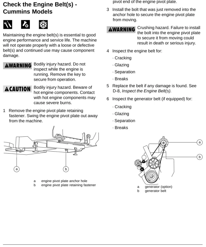
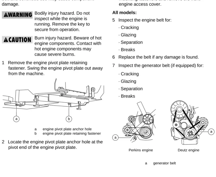
1 Remove the engine pivot plate retaining
fastener. Swing the engine pivot plate out away from the machine.
2 Locate the engine pivot plate anchor hole at the pivot end of the engine pivot plate.
3 Install the bolt that was just removed into the anchor hole to secure the engine pivot plate from moving.
Crushing hazard. Failure to install the bolt into the engine pivot plate to secure it from moving could result in death or serious injury. 4 Inspect the engine belt for:
· Cracking · Glazing · Separation · Breaks
5 Replace the belt if any damage is found. See D-8, Inspect the Engine Belt(s).
6 Inspect the generator belt (if equipped) for: · Cracking
· Glazing · Separation · Breaks
b a
a
TABLE A PROCEDURES
7 Replace the belt if any damage is found. See D-8, Inspect the Engine Belt(s).
Cummins engines are equipped with a serpentine belt and
incorporate a self-adjusting pulley tensioner. No adjustment is required.
8 Remove the engine pivot plate retaining
fastener from the engine pivot plate anchor hole at the pivot end of the engine pivot plate. 9 Swing the engine pivot plate in towards the
machine.
10 Install the bolt that was just removed into the original hole to secure the engine pivot plate.
Crushing hazard. Failure to install the bolt into the engine pivot plate to secure it from moving could result in death or serious injury.
Belts - Genie part numbers
Cummins engine belt 62437
Cummins generator belt 60725
A-7
Check the Engine Cooling Fan
-Liquid Cooled Models
Maintaining the engine cooling fan is essential to good engine performance and service life. The machine will not operate properly with a loose or defective cooling fan and continued use may cause component damage.
Bodily injury hazard. Do not inspect while the engine is running. Remove the key to secure from operation.
Bodily injury hazard. Beware of hot engine components. Contact with hot engine components may cause severe burns.
1 Open the engine side turntable cover and locate the engine cooling fan.
2 Inspect the engine cooling fan for: · Cracking
· Loose rivets (if equipped) · Bent or loose blades
3 Check the fan to make sure it is securely mounted. Tighten the cooling fan mounting fasteners if necessary.
TABLE A PROCEDURES
A-8
Drain the Inline Fuel Filter/ Water
Separator
Proper maintenance of the fuel filter/water separator is essential for good engine
performance. Failure to perform this procedure can lead to poor engine performance and component damage.
Explosion and fire hazard. Engine fuels are combustible. Perform this procedure in an open, well-ventilated area away from heaters, sparks, flames and lighted
tobacco. Always have an approved fire extinguisher within easy reach.
Poor fuel quality or very wet conditions may necessitate performing this procedure more often.
Perform this procedure with the engine off.
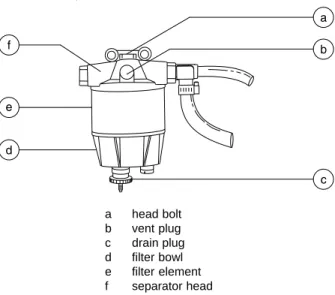
1 Open the engine side turntable cover and locate the fuel filter/water separator.
2 Loosen the vent plug located on the fuel filter/ water separator head.
a head bolt b vent plug c drain plug d filter bowl e filter element f separator head
3 Loosen the drain plug located at the bottom of the bowl. Allow the water to drain into a suitable container until fuel starts to come out.
Immediately tighten the drain plug.
Do not completely drain the fuel bowl.
4 Tighten the vent plug.
5 Clean up any diesel fuel that may have spilled during the procedure.
6 Start the engine from the ground controls and check the fuel filter/water separator for leaks.
If the engine will not start or runs erratically, the fuel system may need to be bled. Refer to B-4, Replace The Fuel Filter/Water
TABLE A PROCEDURES
A-9
Inspect the Engine Air Filter
Maintaining the engine air filter in good condition is essential to good engine performance and service life. Failure to perform this procedure can lead to poor engine performance and component damage.
Perform this procedure with the engine off.
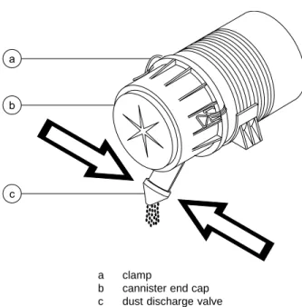
1 Open the engine side cover. Empty the dust discharge valve by pressing together the sides of the discharge slot. Clean the discharge slot as needed.
a clamp
b cannister end cap c dust discharge valve
2 Release the clamps from the end cap of the air filter canister. Remove the end cap.
3 Remove the filter element.
4 Clean the inside of the canister and the canister end cap with a damp cloth.
5 Inspect the filter element. If needed, blow from the inside out using low pressure dry
compressed air, or tap out dust, taking care not to damage the element.
6 Install the filter element.
7 Install the end cap onto the canister. Secure the clamps.
Air filter element
TABLE A PROCEDURES
A-10
Check for Fuel Leaks
Failure to detect and correct fuel leaks will result in an unsafe condition. An explosion or fuel fire could result in death or serious injury.
Explosion and fire hazard. Engine fuels are combustible. Inspect the machine in an open,
well-ventilated area away from heaters, sparks, flames and lighted
tobacco. Always have an approved fire extinguisher within easy reach.
1 Perform a visual inspection around the following areas:
· Fuel tank, shutoff valve, hoses and fittings, fuel pump, fuel filter, fuel injection pumps and fuel injectors.
Explosion and fire hazard. If a fuel leak is discovered, keep any additional personnel from entering the area and do not operate the machine. Repair the leak immediately.
A-11
Check the Hydraulic Oil Level
Maintaining the hydraulic oil at the proper level is essential to machine operation. Improper hydraulic oil levels can damage hydraulic components. Daily checks allow the inspector to identify changes in oil level that might indicate the presence of hydraulic system problems.
Perform this procedure with the boom in the stowed position and the axles extended.
1 Visually inspect the sight gauge located on the side of the hydraulic oil tank.
Result: The hydraulic oil level should be 3/4 inch (19 mm) from the top of the sight gauge.
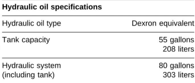
Hydraulic oil specifications
Hydraulic oil type Dexron equivalent
Tank capacity 55 gallons
208 liters
Hydraulic system 80 gallons
A-12
Check for Hydraulic Leaks
Detecting hydraulic fluid leaks is essential to operational safety and good machine performance. Undiscovered leaks can develop into hazardous situations, impair machine functions and damage machine components.
1 Inspect for hydraulic oil puddles, dripping or residue on or around the following areas: · Hydraulic tank—filter, fittings, hoses,
auxiliary power unit and turntable surface · Engine compartment—fittings, hoses,
pumps, filters and turntable surface · All hydraulic cylinders
· All hydraulic manifolds · Boom
· The underside of the turntable · The underside of the drive chassis · Axles
· Ground area under the machine
A-13
Check the Hydraulic Filter
Condition Indicators
Maintaining the hydraulic filters in good condition is essential to good system performance and safe machine operation. The filter condition indicators will show when the hydraulic flow is bypassing a clogged filter. If the filters are not frequently checked and replaced, impurities will remain in the hydraulic system and cause component damage.
There are five hydraulic filters located on the machine. There is two tank return filters, one medium pressure filter and two high pressure filters. All the filters have condition indicators on them, except the drive motor case drain return filter.
1 Start the engine from the platform controls.
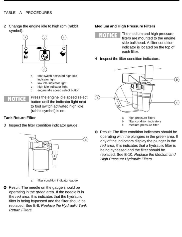
2 Change the engine idle to high rpm (rabbit symbol).
a foot switch activated high idle indicator light
b low idle indicator light c high idle indicator light d engine idle speed select button
Press the engine idle speed select button until the indicator light next to foot switch activated high idle (rabbit symbol) is on.
Tank Return Filter
3 Inspect the filter condition indicator gauge.
a filter condition indicator gauge
Result: The needle on the gauge should be
Medium and High Pressure Filters
The medium and high pressure filters are mounted to the engine side bulkhead. A filter condition indicator is located on the top of each filter.
4 Inspect the filter condition indicators.
a high pressure filters b filter condition indicators c medium pressure filter
Result: The filter condition indicators should be operating with the plungers in the green area. If any of the indicators display the plunger in the red area, this indicates that a hydraulic filter is being bypassed and the filter should be replaced. See B-10, Replace the Medium and High Pressure Hydraulic Filters.
TABLE A PROCEDURES
a
b
c
a c
b
d a
A-14
Test the Platform and
Ground Controls
Testing the machine functions and the Emergency Stop buttons for malfunctions is essential for safe machine operation. An unsafe working condition exists if any function fails to operate properly or either Emergency Stop button fails to stop all the machine functions and shut off the engine. Each function should activate, operate smoothly and be free of hesitation, jerking and unusual noise.
Tip-over hazard. Do not raise or extend the boom unless both axles are extended. If the axle extension system is not operating correctly, the stability of the machine is compromised and it may tip over.
Be sure the axles are retracted before performing this procedure. 1 Turn the key switch to ground controls and pull
out the Emergency Stop button to the ON
position at both the ground and platform controls.
Result: The LCD screen will come on and display no error messages. The beacon (if equipped) should flash.
In cold climates, the LCD readout screen will need to warm up before the display appears. 2 Start the engine.
TABLE A PROCEDURES
3 Push and hold a function enable/speed select button and push the boom up button.
Result: The boom should raise to 10° above horizontal and then stop. The boom should not raise above the limit switch unless both axles are extended.
4 Push and hold a function enable/speed select button and push the boom down button. Result: The boom should lower and return to the stowed position.
5 Push and hold a function enable/speed select button and press the boom extend button. Result: The boom will extend approximately 3 feet (1 m) and stop. The boom should not extend further unless both axles are extended. 6 Push and hold a function enable/speed select
button and push the boom retract button. Result: The boom should retract.
7 Turn the key switch to platform controls. 8 Press down the foot switch.
9 Move the drive control handle in the forward direction and push the extend axle button. Result: The machine should drive and the axles should extend. The indicator light will flash while the axles are moving and stay on when the axles are fully extended.
The extend axle function will only work while the machine is moving.
TABLE A PROCEDURES
10 Stop the machine when the axles are fully extended.
Test the Ground Controls
11 Turn the key switch to ground controls.
12 Do not press and hold a function enable/speed select button. Attempt to activate each boom and platform function button.
Result: No boom and platform functions should operate.
13 Press and hold a function enable/speed select button and activate each boom and platform function button.
Result: All boom and platform functions should operate through a full cycle. Descent alarm (if equipped) should sound while boom is lowering.
Test the Platform Controls
14 Turn the key switch to platform controls. 15 Do not press down the foot switch. 16 Attempt to activate each machine function
control handle, toggle switch or button.
Result: No boom and platform functions should operate.
17 Press down the foot switch.
18 Activate each machine function control handle, toggle switch or button.
Result: All functions should operate through a full cycle. Descent alarm (if equipped) should sound while boom is lowering.
A-15
Test the Auxiliary Power
Operation
Detection of auxiliary power system malfunctions is essential for safe machine operation. An unsafe working condition exists if the auxiliary powered functions do not operate in the event of a main power loss. When operating the machine on engine power, selecting auxiliary power will stop the engine immediately. Auxiliary power is designed for short term use only and excessive use will result in battery drain and component damage.
Perform this procedure with the axles extended and the engine off. 1 Turn the key switch to ground control and pull
out the Emergency Stop button to the ON
position at both the ground and platform controls.
2 Simultaneously push and hold the auxiliary power button and push each boom function button.
To conserve battery power, test each function through a partial cycle.
Result: All boom functions should operate. 3 Turn the key switch to platform controls. 4 Press down the foot switch.
5 Simultaneously press and hold the auxiliary power button and activate each function control
A-16
Test the Tilt Sensor and Alarm
The tilt sensor sounds an alarm located in the platform when the incline of the turntable exceeds the rating on the serial plate.Select a level test area. The tilt alarm should not be sounding prior to the test.
Be sure the engine is off.
1 Turn the key switch to ground controls and pull out the Emergency Stop buttons out to the ON
position at both the ground and platform controls.
2 Push one of the LCD screen buttons shown until TURNTABLE LEVEL X AXIS appears.
Result: The LCD screen should display the angle in degrees.
3 Push one of the LCD screen buttons shown until TURNTABLE LEVEL Y AXIS appears.
Result: The LCD screen should display the angle in degrees.
TABLE A PROCEDURES
4 Push one of the LCD screen buttons shown until PLATFORM LEVEL appears.
Result: The LCD screen should display the angle in degrees.
5 Turn the key switch to platform controls. 6 Push a button, such as the engine RPM button
or the fuel select button.
Result: The alarm should sound at the platform controls.
TABLE A PROCEDURES
A-17
Test the Operating Envelope
Testing the machine operating envelope is critical to safe machine operation. If the boom is allowed to operate outside of the operating envelope, the machine stability is compromised and may tip over. 1 Turn the key switch to ground controls and pullout the Emergency Stop buttons out to the ON
position at both the ground and platform controls.
2 Simultaneously push the LCD screen buttons shown to activate status mode.
3 Push one of the LCD screen buttons shown until BOOM ANGLE is
displayed.
4 Raise the boom and observe the LCD screen. Result: The LCD screen should display:
<10 >10 >50 >65
5 Push one of the LCD screen buttons shown until BOOM LENGTH is
displayed.
6 Extend the boom and observe the LCD screen. Result: The LCD screen should display: at 0
> 0 >80 = 100 >100
7 Retract the boom. 8 Lower the boom.