DRM Introduction and
Implementation Guide
www.drm.org
DIGITAL
radio mondiale
IMPRESSUM
The DRM Digital Broadcasting System
Introduction and Implementation Guide
Copyright:
DRM Consortium, Postal Box 360, CH – 1218 Grand-Saconnex, Geneva, Switzerland
All rights reserved. No part of this publication may be reproduced or transmitted, in any form or by any means, without permission.
Published and produced by the DRM Consortium Editor: Nigel Laflin Date of Publication: August 2012 Designed by: Matthew Ward
For inquiries and orders contact: [email protected]
www.drm.org
Registered address:
DRM Consortium, PO BOX 360, CH – 1218, Grand-Saconnex, Geneva, Switzerland
DRM Project Office, C/o BB Global News
3rd Floor, Brock House, 19 Langham Street, London, W1A 1AA Phone: +44 (0)20-36142310
3
DRMIntroduction and Implementation Guide
The DRM Digital Broadcasting System
Introduction and Implementation Guide
PREFACE
This guide is aimed at the management of broadcasting organisations in areas of policy making as well as in programme making and technical planning. It explains in some detail the advantages gained by radio
broadcasters introducing the DRM Digital Radio Mondiale technology and some of the technical and commercial considerations they need to take into account in formulating a strategy for its introduction.
The guide is a development of the previous ‘Broadcast User Guide’ and includes information on latest system and regulatory aspects for the introduction of the various DRM system variants. It also includes links to reports and articles on an extensive range of highly successful real-life trials.
Digital Radio MondialeTM (DRM) is the universal, openly standardised digital broadcasting system for all broadcasting frequencies up to 240 MHz, including LW, MW, SW, bands I, II (FM band) and III.
DRM is greener, clearer, wider, bigger, better quality & audio content and cost efficient than analogue radio; it provides digital sound quality and the ease-of-use that comes from digital radio, combined with a wealth of enhanced features such as, Surround Sound, Journaline text information, Slideshow, EPG, and data services. DRM on short, medium and long wave for broadcasting bands up to 30 MHz (called 'DRM30') provides large coverage areas and low power consumption. The DRM standard for broadcast frequencies above 30 MHz (called 'DRM+') uses the same audio coding, data services, multiplexing and signalling schemes as DRM30, but
introduces an additional transmission mode optimised for those bands. This provides a digital radio solution for those broadcasters seeking a single service solution (i.e. not part of a multiservice multiplex). The DRM system specification is published as ETSI standard ES 201 980 [1]. A full list of DRM standards and specifications is available on-line at www.drm.org. A summary list is also included in Annex 1.
Readers looking for greater technical detail can refer to a range of published information that covers various specialised aspects of the DRM system and which provides detailed explanations of its operation. The most important ones are noted in Section 12, or are listed on the DRM website: www.drm.org.
The DRM Consortium (Digital Radio Mondiale) is an international not-for-profit organisationcomposed of broadcasters, network providers, transmitter and receiver manufacturers, universities, broadcasting unions and research institutes. Its aim is to support and spread a digital broadcasting system suitable for use in all the frequency bands up to VHF Band III. As of 2012 there are 93 members and 90 Supporters from 39 countries active within the Consortium.
CONTENTS
IMPRESSUM
2
PREFACE
3
2
EXECUTIVE SUMMARY
8
2.1 What is DRM?
8
2.2 Why go Digital?
9
2.3 Key system features
9
3
INTRODUCTION
11
3.1 The objectives of this guide
11
3.2 What’s included in this guide?
11
4
LAUNCHING DIGITAL RADIO SERVICES
13
4.1 Introduction
13
4.2 Critical success factors for Digital Radio
13
4.2.1 Working together promotes success
13
4.2.2 Consumers need a reason to buy
14
4.2.3 Technology solutions need to be readily available
14
4.2.4 Marketing needs to be right
14
4.3 Digital Migration
14
4.4 Migration policy and choice of technology
14
4.5 Migration Strategies
15
4.5.1 ‘Market Seeding’
15
4.5.2 ‘Trojan Horse’ migration
15
5
THE DRM SYSTEM
16
5.1 Principle features
16
5.2 The Broadcast chain
17
5.2.1 DRM content encoding and Multiplexing
17
5.2.2 DRM distribution
18
5
DRMIntroduction and Implementation Guide
5.3.1 Modulation & Coding parameters
20
5.3.2 Service multiplexing and pay-load capacity
21
5.3.3 Single and Multi Frequency Networks
23
5.3.4 Simulcast
24
5.3.5 Alternative Frequency Signalling (Checking and Switching)
25
5.3.6 Programme acquisition
26
5.4 The AM Signalling System (AMSS)
26
6
DRM CONTENT
28
6.1 Broadcast meta-data
28
6.1.1 Service ID {M}
28
6.1.2 Service Labelling {M}
28
6.1.3 Programme Type
29
6.1.4 Service Language
29
6.1.5 Country of origin
29
6.2 Audio content
29
6.2.1 Audio Coding
29
6.2.2 Optimising sound quality
31
6.3 Value-added services
31
6.3.1 Overview
31
6.3.2 DRM Text Messages
32
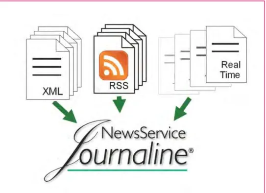
6.3.3 Journaline text information service
32
6.3.4 Electronic Program Guide (EPG)
34
6.3.5 Slideshow
35
6.3.6 TMC (Traffic Message Channel)
35
7
DRM RECEIVERS
38
7.1 DRM Receiver Specifications
38
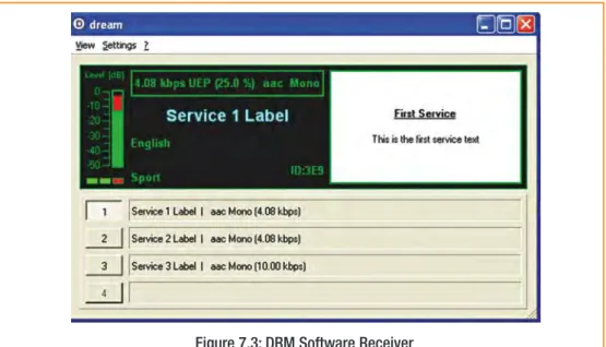
7.2 Receiver development
38
7.3 Software radios
39
7.4 Man-machine interface (MMI)
39
8
REGULATION & STANDARDISATION
41
8.1 Regulation
41
9
BROADCAST NETWORK INFRASTRUCTURE
46
9.1 Programme distribution
46
9.1.1 Multiplex Distribution
46
9.1.2 Network Synchronization
47
9.2 Transmitting in DRM30 modes
48
9.2.1 Overview
48
9.2.2 DRM Amplification
48
9.2.3 Using Non-Linear Amplifiers for DRM
48
9.2.4 The DRM Signal
49
9.2.5 AM transmitter conversion
49
9.2.6 Performance of DRM30 transmitters
50
9.2.7 Out of band Power (OOB)
52
9.2.8 Use of older Transmitters for DRM Trials
53
9.3 Transmitting in DRM+ configuration
53
9.3.1 Network system architectures for DRM+
54
9.3.2 Basic DRM+ setup
54
9.3.3 DRM+ ‘Simulcast Mode’
55
9.3.4 DRM+ combined Mode Setup (signal level combining)
57
9.4 Spectrum masks and protection levels for DRM+
58
9.4.1 VHF Bands I and II
58
9.4.2 VHF Band III
59
9.5 Transmitter Monitoring
59
9.5.1 Characterising Transmitter Performance: the MER
60
9.6 Test Equipment
61
9.7 Antenna Systems
61
9.7.1 MF Antennas
61
9.7.2 LF Antennas
62
9.7.3 Matching and Combining Networks
63
9.7.4 Implementing a DRM Service on an Existing Antenna System
63
10 SERVICE PLANNING
66
10.1 Scope
66
10.2 Network topologies
66
10.2.1 Single Frequency Networks (SFNs)
67
7
DRMIntroduction and Implementation Guide
10.3.3 Band I (47 – 68 MHz)
69
10.3.4 Band II (87.5 – 108 MHz)
69
10.3.5 Band III (174 – 230 MHz)
69
10.3.6 Other VHF Frequency Bands
69
10.4 Planning tools
69
10.5 Planning data for DRM30
70
10.5.1 DRM30 Theoretical S/N ratios
70
10.5.2 DRM minimum field-strengths (MFS)
71
10.5.3 Relative protection and power reduction
74
10.6 Planning data for DRM+
74
10.6.1 Reception modes
74
10.6.2 Correction factors for field-strength predictions
74
10.6.3 System parameters for field-strength predictions – Mode E
75
10.6.4 Single frequency operation capability
76
10.6.5 Minimum wanted field strength values
76
10.6.6 Position of DRM frequencies
78
10.6.7 Protection ratios for DRM
78
10.6.8 Protection ratios for other broadcasting systems interfered with by DRM 82
10.6.9 Sharing Criteria with Other Services
83
10.7 Reception Monitoring
83
11 DRM INTELLECTUAL PROPERTY
84
11.1 Summary
84
11.2 IPR and the DRM Consortium
84
11.3 Licenses for DRM IPR
85
11.3.1 Manufacturers of DRM equipment
85
11.3.2 Marketing of DRM products
85
11.3.3 Use of DRM logo on products
85
12 REFERENCES
87
13 GLOSSARY OF ABBREVIATIONS
89
14 ANNEXES
90
ANNEX 1 – List of main DRM Standards
90
ANNEX 2 – COFDM basics
91
ANNEX 3 – DRM Radio Reciever Profiles
92
DIGITAL
radio mondiale
2
Executive Summary
2.1 What is DRM?
The DRM Broadcasting system has been designed by broadcasters, for broadcasters, but with the active assistance and participation of both transmitter and receiver manufacturers and other interested parties (such as regulatory bodies). It has been designed specifically as a high quality digital replacement for current analogue radio broadcasting in the AM and FM/VHF bands; as such it can be operated with the same channelling and spectrum allocations as currently employed. An overview of the frequency-bands where DRM operates is shown in Figure 2.1.
The DRM standard describes a number of different operating modes, which may be broadly split into two groups as follows:
‘DRM30’ modes, which are specifically designed to utilise the AM broadcast bands below 30MHz, and
‘DRM+’modes, which utilise the spectrum from 30 MHz to VHF Band III, centred on the FM broadcast Band II.
DRM has received the necessary recommendations from the ITU, hence providing the international regulatory support for transmissions to take place. The main DRM standard [1] has been published by ETSI. In addition, ETSI publishes and is the repository of the entire range of current DRM technical standards.
Apart from the ability to fit in with existing spectrum requirements, the DRM system also benefits from being an open system1. All manufacturers and interested parties have free access to the complete technical standards, and are able to design and manufacture equipment on an equitable basis. This has proved to be an important mechanism for ensuring the timely introduction of new systems to the market and for accelerating the rate at
9
DRMIntroduction and Implementation Guide
2.2 Why go Digital?
There is a global trend towards the adoption of digital technology in radio and communications, especially for distribution and transmission. Digitalisation offers many substantial advantages to national and international broadcasters and ‘infocasters’.
We are now seeing the introduction of high quality digital delivery system in homes. Although FM sound broadcasting is gradually moving to a DAB standard in Band III, the possibilities for extending coverage in the FM Band (88-108 MHz) remains limited. For many national and international broadcasters, the advantages of a complementary digital broadcast system below 30 MHz are becoming clear. However, the limited fidelity of existing AM services is causing listeners to search for other alternatives.
Implementation of digital radio in today's AM bands (i.e. long, medium and shortwave) will enable operators to provide services which will be successful with both existing and future high-quality services operating on other parts of the dial. Digital broadcasting on short-, medium-, or long wave (AM) has many advantages when compared to the conventional analogue system we use now.
DRM+ has a narrow bandwidth that provides an ideal ‘digital’ solution for those regional and local broadcasters for whom a broadband-shared multiplex is not suitable. The coverage can be tailored to the individual
broadcasting station requirements and there are no complex and potentially expensive multiplex agreements to negotiate. Furthermore, the high commonality with the existing DRM standard allows easy and fast equipment implementation. It is therefore a flexible solution allowing single or small numbers of audio services to be broadcast together.
The introduction of DRM services allows a broadcaster to provide listeners with significant improvements in service reliability, audio quality and, most importantly, usability. By usability we mean those features that enhance the listener experience, as outlined below.
The DRM standard provides many features and facilities that are impossible to replicate in analogue
broadcasting. It is essential that prospective broadcasters understand the potential and flexibility of the system in order to allow them to optimise and configure their DRM networks in accordance with their particular market conditions.
From a technical perspective, a key and revolutionary feature of DRM is the ability to select from a range of transmission modes. This allows the broadcasters to balance or exchange bit-rate capacity, signal robustness, transmission power and coverage. What’s more, it is possible to do this dynamically, in response to any local changes in the environment, without disturbing the audience. A classic problem that can be mitigated by this feature is dealing with night-time sky-wave interference in the AM bands.
Furthermore, DRM is the only digital radio system that embraces all the currently used radio frequency bands; it provides an ideal replacement for existing analogue services as well as complementing existing digital services such as DAB.
From a commercial perspective, there is no demand from audiences to ‘consume’ digital services for their own sake. It is essential therefore that the audience is presented both with receivers at prices it is prepared to pay and, more importantly, an attractive package of benefits:
• The availability of a wider range of services,
• Easier tuning and selection of programming – e.g. automatic switching between different transmitters or electronic programme guides.
• Improved formats such as stereo in the ‘AM bands’ and surround-sound in cars, • Improved and more consistent sound quality
• Programme-associated data, textual content description or even independent services such as traffic information
The importance of quality content, while outside the scope of this guide, cannot be stressed too highly. Subsequent sections of this guide provide more detailed information on these enhancements.
2.3 Key system features
The system is specifically designed to allow the new digital transmissions to co-exist with the current analogue broadcasts, and a significant amount of work has been undertaken to quantify the operating
parameters that assure mutual analogue and digital compatibility. Hence the changeover from analogue to digital broadcasting can be phased over a period of time, which in turn allows existing broadcasters to spread the required investment to meet any budgetary constraints. Furthermore, unlike some other digital systems, the DRM
system has been designed to allow suitable analogue transmitters to be modified to switch easily between digital and analogue broadcasts. This can significantly reduce the initial investment cost for a broadcaster. An additional budgetary benefit is the reduction of transmission energy costs.
DRM exploits the unique propagation properties of the AM bands. The introduction of DRM30 services allows a broadcaster to provide listeners with significantly improved audio qualityand service reliability. As a result, international broadcasters can provide services on SW and MW that are comparable to local FM services, whilst enhancing the listener experiencewith easier tuning and added data services. National and local LF and MF broadcasters will derive similar benefits.
This is not all; a summary of the key benefits of DRM for the listeners, manufacturers, broadcasters and regulators is given in Figure 2.3.
In the VHF bands, DRM+ can be configured to useless spectrumthan current stereo FM broadcasts, whilst additionally deriving the potential benefits of increased robustness, reduced transmission power, increased coverageor additional services.
DRM is unique in providing an extensive and extremely powerful ‘toolkit’ array of operating modes and
techniques, which allow a broadcaster to tailor the system to best meet the needs of his or her particular market. For instance, DRM allows the independent selection of modulation parameters (code-rates, constellation, guard-intervals etc.) to enable an optimum trade-off between capacity and signal robustness. DRM also supports both multi- and single-frequency network operation, (MFN/SFN), and hand-over to other frequencies and even other networks(AFS – Automatic Frequency Checking & Switching). This latter feature allows a broadcaster operating on several different platforms to hand a listener from DRM to AM, FM or DAB and back again. The appropriate signalling is intrinsically supported by DRM and DAB, and by data carriers on AM and FM (AMSS and RDS respectively).
Of particular note amongst the various data services is the DRM Electronic Programme Guide(EPG), which allows listeners with appropriate receivers to access the broadcast schedule and set recording times accordingly,
Figure 2.3: Key Benefits of DRM
• Excellent quality sound in stereo DRM30, CD quality in DRM+ • Data such as text, pictures and Journaline
• Easy tuning on station name
• Replace receivers with new digital receivers • Increase the market potential
• Increase possibilities for new areas of interest and content
• Multilingual programme are possible plus extra information • Reduced power consumption of up to 40-50%
• Increased opportunity for revenue generation streams
• Uses less spectrum and release spectrum for other use • An international standard
• Lower power costs – green broadcasting • Emergency warning alert
LISTENERS
MANUFACTURERS
BROADCASTERS
11
DRMIntroduction and Implementation Guide
3
Introduction
3.1 The objectives of this guide
This document is written primarily as a guide to radio broadcasters contemplating a transition from analogue to digital broadcasting in the AM and VHF broadcasting bands. It will also be of value to manufacturers, service-planners, administrations and regulatory bodies involved with broadcasting systems and/or policy. The document is intended to:
• Explain how and why a broadcaster might go digital, from both technical and commercial perspectives.
• Describe the basic operation of the DRM system and its many features.
• Provide a definitive source of references to key technical standards, including regulatory, co-ordination and planning information for DRM broadcasting.
• Supplement various existing documents, as appropriate.
• Provide information on where to find additional material on the practical experiences and know-how that DRM members, broadcasters and supporters have gained from several system trials.
3.2 What’s included in this guide?
This guide provides more detailed information on both the techniques described above and other useful features, such as bespoke commercial applications designed to run on the DRM platform. The techniques are generally applicable equally to international, national and local services.
This document addresses the following aspects of the DRM system in particular, and Digital Radio in general:
• Launching Digital Radio:Includes a summary of the critical success factors and lessons learnt by broadcasters who have migrated and launched digital radio services.
• DRM Technology:Description of the broadcast chain and main features of the DRM System, followed by a look at the options for tailoring a DRM system to broadcasters’ requirements. The DRM System section also introduces multi- and single-frequency networks, alternative-frequency signalling and DRM simulcast options.
• DRM Content:This section covers all aspects of DRM content, from essential meta-data relating to receiver tuning through audio coding and quality issues, to finally, an overview of value-added services.
• Broadcast Network Infrastructure:contains a description the broadcast network from studio output through to the radiated signal. This section includes a wealth of practical knowledge related to DRM transmitter specifications, antenna systems, programme distribution, network synchronisation and information relating to transmitter measurements and monitoring equipment.
• DRM receivers: It provides an overview of recent DRM receiver technology and relevant specifications.
• Regulatory aspects and Service Planning:Information on how DRM services may be introduced into the bands with respect to the HFCC planning process in the SW bands, and the existing Regional Plans covering the LW and MW or higher frequency bands. Specialised applications such as NVIS (Near Vertical Incidence Sky-wave) and SFN (Single Frequency Networks) are also explained here. Information is also included here on how transmissions may be monitored in order to verify coverage. In addition, this guide includes information on the regulatory and planning aspects for the introduction of DRM+ in the VHF frequency bands.
• IPR:A description of DRM branding and logos, together with a description of the DRM technology licensing process.
Annexes:Further technical descriptions of the DRM system and related technology, together with reference to published articles and system trials.
Advertisement
Thomson Broadcast Systems
Expertise and Innovation
Paving the way towards digital radio broadcasting
Thomson Broadcast AG
13
DRMIntroduction and Implementation Guide
4
Launching Digital
Radio Services
4.1 Introduction
Building a digital radio network is relatively easy. Migrating listeners and/or building an audience from scratch is a significant challenge. Over the last decade this has been amply demonstrated in a diversity of markets and driven by both public and commercial radio consortia. It is instructive to examine the underlying reasons for this situation, and indeed for those markets where digital radio has achieved some success, much analysis has already been undertaken to understand both the mistakes made and the critical success factors involved. These are summarised below.
4.2 Critical success factors for Digital Radio
Several factors have all been identified as key determinants to success in building an audience on digital radio. The principle challenge lies in getting digital receivers into the market in volume. Inevitably, for a new technology, we’re starting from an installed-receiver base of zero. Consumers need to be initially made aware that exciting new services are on-air, and then be told how they can receive them. These are marketing issues.
The approach taken by an individual broadcaster will clearly be dependent on a number of factors, not least the budget available, access to broadcast spectrum, the nature, competitiveness and maturity of the local radio market, and the demographics of the target audience.
4.2.1 Working together promotes success
All the stake-holders need to be co-ordinated and committed to the launch of digital radio services to reduce overall risk. Factors that are crucial to ensuring success include:
• Regulatory incentives and support from the local administration.
• Ideally, all broadcasters operating in the same region (both commercial and public service) participating in the launch, or at least a grouping with sufficient resources to launch a critical mass of new services. • Similarly, the full engagement of transmission providers, and crucially, retailers and receiver manufacturers. Getting the whole process started involves a series of logical conditions to be met. These feed back ‘positively’ in a loop, which fundamentally requires the broadcaster to take the initiative:
In some countries this process is aided and the loop ‘booted’ through the formation of one or more. National Platforms, where plans are developed and co-ordinated and funding agreed.
Consumers won’t buy new radio products unless there is a compelling reason to buy (exciting new content, ‘must have added-value services or features, etc.)
Retailers won’t stock new products unless they can see consumer demand.
Manufacturers will not produce radios without retailers’ orders.
All too frequently, a broadcaster will not launch new digital services due to an absence of digital radios or very low market penetration.
4.2.2 Consumers need a reason to buy
The most powerful driver found to date is access to new content. There are other drivers, for instance ease of use and launching services with an absence of advertising into a market where such advertising is perceived as intrusive by a large section of the audience. Additionally;
• Benefits need to match price of entry.
• Improved quality has only marginal attraction: there may be some examples where this does assist take-up, but it is very much a secondary factor.
4.2.3 Technology solutions need to be readily available
• It goes without saying that the receiver industry must play its part in ensuring that products are available at the right moment and at the right price-point. Creating a strong initial demand through appropriate
marketing assists in raising volumes and reducing costs. 4.2.4 Marketing needs to be right
• It is essential that the marketing of the new services is sustained and high profile. Existing broadcasters can use their own media to cross-promote: television, radio and on-line. Competitions can be held with prizes of digital radios. Using creative scheduling, it is possible to entice people to use digital services by, for
example, pre-releasing prime content on digital ahead of analogue, or vice-versa, using the digital service to repeat programmes which were missed the first time round.
It is important that all stakeholders play their part for the greater good. Each party may perceive high risks (though not at the same time); a collaborative model reduces these risks as far a possible and should lead more quickly to success.
4.3 Digital Migration
The DRM system was specifically designed to align with and make use of current analogue spectrum allocations to co-exist with current analogue broadcasts2. This allows broadcasters to make the required investment on a
timescale that meets their budgetary needs. It will ensure that expensively acquired and perfectly satisfactory transmission equipment and infrastructure is not suddenly made obsolete. Suitable analogue transmitters can be modified to switch between digital and analogue broadcasts, further reducing the initial investment required for a broadcaster wishing to migrate to DRM. This in turn allows broadcasters to focus their capital resources on new content and services. Additionally, the reduction of the transmitting energy costs allows additional revenue savings, which can be ploughed back into programming.
Apart from the ability to fit in with existing spectrum requirements, the DRM system also benefits from being an ‘open’ system, allowing any manufacturer to design and manufacture equipment on an equitable basis. This has proved, in the recent past, to be an important mechanism for ensuring the timely introduction to market of new systems and for accelerating the rate at which equipment prices reduce. This is a significant consideration for broadcasters but even more so for the millions of listeners who will need to invest in new, DRM-capable receivers.
4.4 Migration policy and choice of technology
It is clearly important for any administration regulating broadcasting to choose the systems used for digital broadcasting, both radio and TV, in order to avoid consumer confusion and a proliferation of standards. It also avoids the premature writing-off of investments made by broadcasters in the ‘wrong’ technology.
Factors that might become of greater importance in the 21st century include:
• Energy constraints:choice of system to minimise power consumption in both transmitters and consumer receivers. Efficient network planning and robust transmission parameters play a key part, optimising
coverage and avoiding excessive transmitter power levels.
• Economic and Social benefitswhich might flow from, for instance, the provision of universal real-time traffic information, or local design and manufacture of digital receivers.
15
DRMIntroduction and Implementation Guide
• Market Regulationwhich works toward the common-good, and avoids the disenfranchisement of some listeners and/or broadcasters. For instance, this might include the requirement to co-site transmitters to avoid local ‘holes’ being punched in the service area of other radio stations, and a mandate that radio receivers should incorporate all relevant standards used for radio within the territory.
4.5 Migration Strategies
Many creative solutions have been proposed which address the issue of how to initially launch a new digital service when there are no receivers in the market.
4.5.1 ‘Market Seeding’
The most radical example of this technique requires an up-front investment in receivers: the broadcaster places an order for a large quantity of digital receivers, which are then either given to consumers or sold with a
significant discount. One broadcaster proposed purchasing 500,000 receivers, and free-issuing to taxi-cabs, retails outlets and domestic consumers. This strategy yields a low initial receiver cost, combined with the ability to guarantee potential advertisers a sizeable audience from day one.
4.5.2 ‘Trojan Horse’ migration
The ‘Trojan Horse’ approach to digital migration has the potential to seed the market with digital radios ahead of a formal digital radio service. This serves as a catalyst to the launch process and boots the positive feedback loop described earlier. The technique is simply to introduce and market new ‘analogue’ receivers which include some new or distinctive features which are either intrinsic to the radio itself (e.g. recording-to-memory, radical styling), and, or can be readily supported by existing broadcasts (some RDS or AMSS data service etc.).
These new radios also support DRM, but initially this is not the key feature used for marketing; the DRM function is ‘hidden’, and hence the term ‘Trojan Horse’. In this scenario, it is clearly vital to have a medium-term strategy agreed and co-ordinated with the receiver manufacturers. Once sales have reached some target, digital services can be launched to an audience that is ready-equipped with receivers.
Nautel’s Advanced User
Interface (AUI) gives you
more
DRM
transmitter
control and instrumentation
at the transmitter site, office
or even your living room.
Learn more at
www.nautel.com/drm
MORE CONTROL
+1.902.823.5131 www.nautel.com/drm
5
The DRM System
This section includes a brief description of some of the more important features and supported services of the DRM system, followed by an overview of the main components found in the broadcast chain.
5.1 Principal features
DRM30 uses the existing AM broadcast frequency bands and is designed to fit in with the existing AM broadcast band plans, based on signals of 9 kHz or 10 kHz bandwidth. It also has modes requiring only 4.5 kHz or 5 kHz bandwidth (AM), and modes that can take advantage of wider bandwidths – 18 kHz or 20 kHz.
DRM+ has a narrow bandwidth and is designed to fit in the FM broadcast band plan with a frequency grid of 100 kHz. Its small spectrum needs supports its use in crowded bands. DRM+ provides bit rates from 35 kbps to 185 kbps and, like DRM, permits up to four services. It is therefore a flexible solution allowing single or small
numbers of audio services to be broadcast together.
The above features allow DRM to operate alongside existing analogue transmissions in every world market. The DRM system uses COFDM (Coded Orthogonal Frequency Division Multiplex). This means that all the data, produced from the digitally encoded audio and associated data signals, is shared out for transmission across a large number of closely spaced carriers. All of these carriers are contained within the allotted transmission channel. Time interleaving is applied in order to mitigate against fading. Various parameters of the OFDM and coding can be varied to allow DRM to operate successfully in many different propagation environments - the selection of the parameters allows transmissions to be planned that find the best combination of transmit power, robustness and data capacity.
The DRM system uses MPEG 4 HE AAC v2 for mixed programming providing high quality at low data rates. In addition, CELP and HVXC coders are included in the specification to provide speech-only programming at even lower data rates.
From a broadcaster’s perspective, DRM offers a wealth of features and a powerful array of options. For instance, DRM provides support for
• Broadcasting in all frequency bands (LF/MF/HF and Bands I, II, II) currently used for AM and FM analogue radio.
• Migration from, and co-existence with, analogue broadcasting: complies with existing spectrum masks and analogue frequency grids.
• Up to four services per frequency, each of which can be any mixture of audio and data.
• Single-frequency and multi-frequency networks, plus associated signalling and automated receiver tuning.
• a choice of three audio coders supporting bit-rates from 2kb/s upwards.
• text-messaging, slide-shows, multi-media object transmission, traffic and news headlines and a wide range of similar value-added services.
DRM additionally offers assistance to broadcasters and manufacturers by virtue of publishing an extensive range of open standards3, which support the main system standard [1]
Above all else DRM is designed to improve the listener experience though a combination of improved usability, improved audio quality and data-enhancements to the audio content.
17
DRMIntroduction and Implementation Guide
5.2 The Broadcast chain
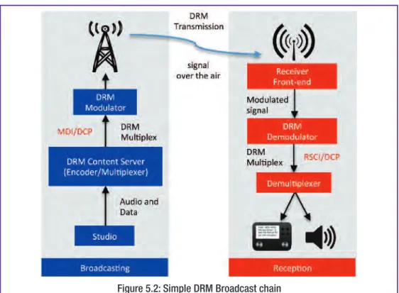
Figure 5.2 shows a very simple ‘single-service, single transmitter’ broadcast chain and depicts the general flow of different classes of information (audio, data, etc.) from their origination in a studio or control centre on the left of the figure to a DRM receiver on the right.
In the following sections we will examine the operation of the two main functional blocks shown above: the Content Server and the Modulator. In most (but not all) installations, these functional blocks correspond to commercially available products. They communicate via a Multiplex Distribution interface (MDI) over a Distribution and Communications protocol (DCP), both of which have been standardised [2], [3].
5.2.1 DRM content encoding and Multiplexing
These functions may be integrated into a product that is known as a Content Server (Figure 5.2.1).
Figure 5.2: Simple DRM Broadcast chain
Setting aside local control and command interfaces, there are two basic classes of input information: i. The encoded audio and broadcast data services which form the Main Service Channel (MSC);
ii. Information which travels via the Fast Access Channel (FAC)and Service Description Channel (SDC). These channels communicate service identification and parameter selection for a transmission and ensure that the appropriate decoding parameters are selected within a receiver.
• The FAC contains a set of core parameters required to quickly check for available services within a multiplex and to allow de-modulation of the DRM signal.
• The SDC carries advanced information like audio and data coding parameters, service labels, current time and date, AFS tables (Alternative Frequency Signalling), etc.
The audio encoderand the data encodersensure the adaptation of the input streams into an appropriate digital format. The output of these encoders may optionally comprise a higher and a lower protected part, each of which will be given one of two different protection levels within the subsequent channel encoder.
The multiplexercombines the protection levels of all data and audio services, in a defined format, within the frame structure of the bit stream.
If the audio coding and multiplexing is performed remotely from the transmission site (as is the norm), the signal is distributed using the Multiplex Distribution Interface (MDI)protocol, described below.
5.2.2 DRM distribution
To enable both the audio and data services, (together with the associated transmission parameter data) to be combined into one transmission feed, DRM has specified a standardised and efficient method for combining all this data into a single multiplex; known as
• the MDI (Multiplex Distribution Interface [2]) , which in turn employs a standardised protocol;
• the DCP(Distribution and Communications Protocol [3]).
Although the broadcaster is strongly advised to locate the audio encoder and/or DRM Content Server at the studio centre, (for the reasons set out under 6.2.2 Optimising Sound Quality), there remains the option of distributing the audio to a DRM multiplexer at the transmitter site, in which case the existing programme distribution system would likely be used. There will be additional information required for the operation of the multiplexer, which would not typically be required for, say, an analogue AM service. This information relates to the choice of audio coding, audio data rate, AFS list, transmission Mode (A, B, C, D & E), modulation (e.g. 4, 16, or 64QAM) and transmission bandwidth etc. This must be supplied to the multiplexer and encoder to ensure that the correct parameters are used for a particular transmission. This will be particularly relevant to SW
transmissions, but less so for ‘fixed’ services on VHF frequencies.
5.2.3 DRM Coding and Modulation
MDI Interface
MDI/DCP Input
P Input erface
19
DRMIntroduction and Implementation Guide
• The energy dispersal provides a 'randomising' of the bits that reduces the possibility of unwanted regularity in the transmitted signal.
• The channel encoder adds redundant bits to the data in a defined way, in order to provide a means for error protection and correction, and defines the mapping of the digitally encoded information into QAM cells. These are the basic carriers of the information supplied to the transmitter for modulation.
• Cell interleaving rearranges the time sequence of the signal bits in a systematic way as a means of "scrambling" the signal, so that the final reconstruction of the signal at a receiver will be less affected by fast fading than would be the case if speech or music data were transmitted in its original continuous order.
• The pilot generator injects non-data carriers of prescribed amplitude and phase which permits a receiver to derive channel-equalisation information, thereby allowing coherent demodulation of the signal.
• The OFDM cell-mapper collects the different classes of cells and places them on a time-frequency grid, in effect distributing the information across the sub-carriers.
The output from the Modulation process can take one of several forms:
i. A complex waveform representing the broadcast signal, already modulated onto an IF or RF frequency ii. Analogue or digital representations of In-phase and Quadrature base-band signals (“I-Q”): the I-Q signals
can then be used to modulate an IF or RF carrier
iii. Analogue or digital representations of Phase and Amplitude signals, (which can be derived from a transform of the I-Q signals) : this signal format is known as “A-RFP”
The A-RFP signal is of particular importance for DRM amplification using the traditional transmitter topography employed by high-efficiency AM transmitters. This is described in greater detail in Section 9.
5.2.4 Broadcast signal framing
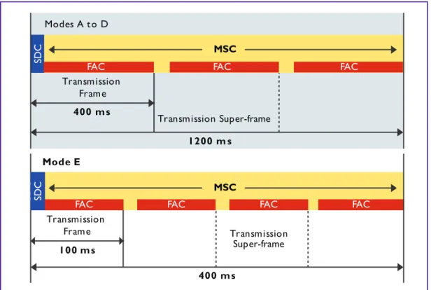
Figure 5.2.4 shows the framing and temporal relationship between the three basic classes of transmitted data. The scheme employed is governed principally by the requirements of receivers for tuning, re-tuning and content operations
The data carried in the FAC is not time-interleaved, and is confined to a specific group of carriers in the frequency-domain. This enables the receiver to rapidly achieve synchronisation and determine the modulation parameters used for the MSC.
The SDC is broadcast across all carriers for a period of two symbols at the start of each super-frame. This data is normally static and hence repetitious; this allows a fully-synchronised receiver to use this period for alternative frequency switching (see section 5.3.5).
5.2.4.1 Fast Access Channel structure
The FAC’s structure is built around a 400 or 100ms frame (Figure 5.2.4). The FAC is used to provide information on the channel parameters required for the de-modulation of the multiplex as well as basic service selection information for fast scanning.
The channel parameters (for example the spectrum occupancy and interleaving depth) allow a receiver to quickly decode the multiplex. It also contains information about the services in the multiplex which allow the receiver to decide to either decode this multiplex or, if the desired service is not present, to change frequency and search again.
Each transmission frame contains an FAC block. An FAC block contains parameters that describe the channel and parameters to describe either one or two services along with a CRC (Cyclic Redundancy Check).
For robustness modes A, B, C and D, the FAC block contains parameters that describe both the channel together with one set of service parameters, along with a CRC.
For robustness mode E, the FAC block is similarly configured but includes two sets of service parameters. When more services are carried in the multiplex than can be described within one FAC block, a number of FAC blocks are required to describe all the services.
Full details and a description of the FAC structure and contents can be found in Section 6.3 of the DRM specification [1].
5.2.4.2 Service Description Channel structure
The SDC contains information on how to decode the MSC, how to find alternative sources of the same data, and gives attributes to the services within the multiplex.
The SDC’s frame-periodicity corresponds to the super-frame length (1200 or 400 ms), as defined by the DRM mode. The data capacity of the SDC varies with the spectrum occupancy of the multiplex and other parameters. Making use of the AFS index can also increase the SDC capacity.
Alternative frequency checking may be achieved, without loss of service, by keeping the data carried in the SDC quasi-static. Therefore, the data in the SDC frames should be carefully managed.
The SDC conveys key data and information, including:
• Multiplex description
• Alternative frequency signalling
• Announcement support and switching
• Time and date information
• Audio information
• FAC channel parameters
• Language and country data
• Signalling of reconfigurations
A comprehensive description of the SDC’s structure and many components can be found in Section 6.4 of the DRM specification [1].
5.3 Configuring the DRM system
The following sections describe how the various component parts of the DRM system work together in order to provide a system that can be optimised to meet the broadcaster's specific requirements for quality and number of audio services, data services and service robustness.
5.3.1 Modulation & Coding parameters
This section provides an indication of how some of the DRM signal parameter options might be used for typical applications. The following paragraph provides more detail on how these parameter options might best fit the broadcaster's particular coverage requirements.
21
DRMIntroduction and Implementation Guide
spanning some 3 decades. Propagation in the AM bands can range from ground-wave, where electrical noise is the predominant interference mechanism, to sky-wave with varying degrees of channel complexity and where both differential delay and Doppler effects are additional adverse factors. In some circumstances signals may reach some locations in the coverage area by means of both types of propagation. In all of these cases the received signal is likely to suffer from the addition of distortions or noise, which have been caused by the imperfect transmission path.
Hence the system defines five pre-set “Modes”, labelled A to E respectively, which are outlined in Table 5.1 below.
• Mode A is designed to deliver the highest bit rate possible within the context of ground-wave or line-of-site coverage.
• Mode B will generally be the first choice for sky-wave services.
• Where propagation conditions are more severe, such as for long paths with multiple hops, or near vertical incidence, where several very strong reflections may occur, Mode C or Mode D may need to be employed.
• Finally, Mode E is used for the VHF frequency bands from 30 MHz up to Band III (DRM+). ii. Modulation parameters
In addition to the basic transmission Modes, there is also a choice of modulation (QAM constellation) and coding (Viterbi) rates for the main service channel. Normally, provided the broadcaster has selected the transmission mode correctly, the service area achieved should be defined predominantly by the received signal-to-noise ratio. This allows the use of simple analogue planning tools (see Section 10)
In all DRM30 Modes the option exists to choose either 64QAM or 16QAM for the Main Service Channel, and this choice will be largely influenced by the signal-to-noise + interference ratio (SNR) that can be achieved in the target area. The more robust 16QAM option is normally chosen where the SNR is expected to be too low to support 64QAM. For DRM+ (Mode E), it is possible to employ either 16QAM or 4QAM for the Main Service Channel.
5.3.2 Service multiplexing and pay-load capacity
Within the constraints of the modulation parameters required to deliver the required quality of service, the broadcaster has some flexibility in the way the available capacity of the MSC is used. The broadcaster may wish to allocate some of the capacity to provide a data service alongside the audio, or to split the capacity to provide more than one audio service. Examples might be a high-quality service, containing music and speech, together with a low bit-rate speech service, carrying news headlines or a similar voice-only information service such as traffic updates.
Table 5.3.2 ‘DRM system Bit Rate Table’ sets out the range of bit rates that are available for different levels of signal robustness and channel bandwidth. The smallest bit-rate increment is 20bps in DRM30 modes, and 80bps (DRM+).
Table 5.3.1: DRM Transmission modes
Mode A B C D E DRM30 modes DRM+ MSC QAM options 16, 64 16, 64 16, 64 16, 64 4, 16 Bandwidth options (kHz) 4.5, 5, 9, 10, 18, 20 4.5, 5, 9, 10, 18, 20 10, 20 10, 20 100 Typical uses
LF & MF ground-wave, 26MHz band line-of-sight HF & MF transmission on sky-wave
Difficult sky-wave channels on HF
NVIS sky-wave (highest Doppler & delay spread) VHF transmissions in the bands above 30 MHz
In DRM, a ‘Service’ may be either audio or data:
• Audio services consist of one audio component, plus either zero or one associated data component.
• Data services consist of one data component.
A streammay contain one audio component plus one data component in synchronous stream mode, or up to 4 data components in packet mode – see figure 5.3.2.
Table 5.3.2: The DRM system Bit Rates
Mode A B C D E MSC Modulation (nQAM) 64 16 64 16 64 16 64 16 16 4 Robustness level Min. Max. Min. Max. Min. Max. Min. Max. Min. Max. Min. Max. Min. Max. Min. Max. Min. Max. Min. Max. 4.5 14.7 9.4 7.8 6.3 11.3 7.2 6.0 4.8 5 16.7 10.6 8.8 7.1 13.0 8.3 6.9 5.5 9 30.9 19.7 16.4 13.1 24.1 15.3 12.8 10.2 10 34.8 22.1 18.4 14.8 27.4 17.5 14.6 11.6 21.6 13.8 11.5 9.2 14.4 9.1 7.6 6.1 18 64.3 40.9 34.1 27.3 49.9 31.8 26.5 21.2 20 72.0 45.8 38.2 30.5 56.1 35.8 29.8 23.8 45.5 28.9 24.1 19.3 30.6 19.5 16.2 13.0 100 186.3 99.4 74.5 37.2 Nominal Signal Bandwidth (kHz)
23
DRMIntroduction and Implementation Guide
The system is flexible in other ways as well, in that the broadcaster has the facility to vary the occupied
bandwidth of the signal to exploit the spectrum available in different frequency bands and in different regions of the world. Alternatively, where planning conditions allow, double bandwidth signals (18 or 20 kHz bandwidth) can be transmitted in the AM bands to provide an increased level of audio quality.
5.3.3 Single and Multi Frequency Networks
The DRM system is capable of supporting Single Frequency Network (SFN)operation. This is the case where a number of transmitters transmit, on the same frequency, identical DRM signals. Generally these transmitters are arranged to have overlapping coverage areas, within which a radio will receive signals from more than one transmitter. Provided these signals arrive at the receiver within a time difference of less than the guard interval, they will provide positive signal reinforcement. Therefore the service coverage will be improved at that location, compared to that obtained if there was only a single transmitter providing service at that location.
By careful design, and using a number of transmitters in a SFN, a region or country may be completely covered using a single frequency, rather than a number of different frequencies, thus dramatically improving spectrum efficiency.
Figure 5.3.3 illustrates how an existing UK national network, currently using five analogue MF frequencies, could be migrated to a DRM SFN, thus releasing four channels for other services.
Figure 5.3.2: Relationship between DRM Services and MSC ‘Streams’
National Network 3 -1215kHz
+
National Network 3 -1215kHz+
--3 3 ork ork w w Net Net ional ional Nat Nat 1215kHz 1215kHz++
Where use of an SFN may be impractical for some reason, a Multi-Frequency Network (MFN)may be employed. In this case the transmitted DRM signals are identical but the frequency used for each transmitter is different. The DRM signal provides a short period during which no MSC data is transmitted. This is not audible to the listener as the data is re-timed in the receiver to ensure continuous data arrives at the audio decoder.
However this period provides a short time interval, during which the receiver may tune to an alternative frequency carrying the same programme, in order to determine its signal quality.
If the quality on the alternative frequency is better, the receiver can stay on that frequency, if not it can return to the original frequency. However this operation will only work seamlessly if the signals on the alternative
frequencies are accurately synchronised at the receiver. MFN operation relies on the use of AFS signalling, as described below in Section 5.3.5. Where a receiver is equipped with dual signal-decoding chains, it is possible to compare two or more signals on a continuous basis or even combine the signals to provide a significant
improvement in reception reliability through frequency and propagation-path diversity.
5.3.4 Simulcast
5.3.4.1 DRM30 Modes
Simulcast is an option of particular interest to broadcasters who have to continue to satisfy existing analogue listeners for several years to come, but who wish to introduce DRM services as soon as possible. In many cases these broadcasters are restricted in the ways in which the digital service can be introduced. For example they may have a single MW assignment and no prospect of receiving an additional frequency assignment to start a digital only version of their service. They may also be keen to avoid having to make a short-term investment in an additional transmitter and/or antenna and site to start a digital service on a new frequency. These broadcasters would like to be able to transmit simultaneously both the existing analogue service and a new DRM service, with the same content, whilst using the existing transmitter and antenna. This option is probably most applicable to broadcasters with LW or MW assignments, where there is generally less freedom to use new frequencies, although there may be similar SW applications where NVIS is used for domestic radio coverage. Nevertheless, it is now the case that Broadcasters in Europe are either closing or considering closing down LF and MF services and this would offer an ideal opportunity for the introduction of new digital radio services.
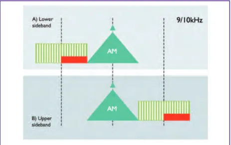
Strictly the term simulcast can be taken to describe the simultaneous transmission of more than one signal carrying the same programme content. In this context it often describes the simultaneous transmission of analogue and digital versions of the same programme from the same transmitter and therefore from a common location. In some cases it could be more economic to add a new lower powered transmitter for the DRM service, feeding the same antenna, rather than making extensive modifications to an older less suitable transmitter currently carrying the analogue service. DRM supports a number of different simulcast options. ETSI standard TS 102 509 [Annex 1, 3)] describes a single-channel simulcast mode for 9/10kHz channels (Figure 5.3.4.1a) whereby the upper sideband is replaced with a 4.5/5kHz DRM signal, and the lower sideband is processed and shaped to produce a resultant composite envelope which can be demodulated by a conventional AM receiver.
However, the more attractive simulcast modes require the use of either 18kHz channels or additional spectrum outside an assigned 9 kHz or 10 kHz channel in a Multi-Channel or Multi-frequency Simulcast (MCS)
configuration. The DRM signal can be located in the next adjacent upper or lower channel (see Figure 5.3.4.1b) and can occupy a half or whole channel depending on the bandwidth option chosen. Significant testing, both in the laboratory and in the field, has been carried out to determine the optimum level of DRM signal needed to provide a good quality DRM service, whilst avoiding significant impact on the analogue service.
25
DRMIntroduction and Implementation Guide
The conclusion is that a satisfactory compromise can be obtained when the level is around 14-16 dB below the adjacent analogue carrier level.
5.3.4.2 DRM+ Mode E
FM and DRM+ simulcast working is described in Section 9.3.2.
5.3.5 Alternative Frequency Signalling (Checking and Switching)
Alternative Frequency Switching forms an integral part of the mechanism allowing the use of MFN’s. The AF (alternative frequency) list is transmitted in the SDC part of the DRM multiplex and provides the receiver with a list of frequencies carrying the same programme or associated programmes. The AF list can also provide information on non-DRM services, such as analogue AM, FM and DAB multiplexes that carry the same or
associated programme. Depending on the coverage of the receiver, it may therefore be able to switch backwards and forwards between these other types of transmissions and the DRM service(s).
There are two distinct modes of Alternative Frequency switching, as follows:
• SeamlessAFS, whereby the receiver re-tunes with virtually no break in the audio. This is illustrated in Figure 5.3.5. Note that this mode requires network synchronisation similar to a single-frequency network, and seamless switching is only supported between DRM transmissions.
• Generic AFS, which allows the receiver to be directed to another transmission carrying the same service, and which is not constrained to be either a DRM broadcast nor time-synchronised.
Figure 5.3.4.1b: Adjacent-channel Simulcast Overview
An example of ‘generic’ AFS might be a metropolitan FM service, carrying RDS, which points to a DRM frequency. Outside the metropolitan area the coverage might be extended by using one or more DRM transmitters so that a car receiver could switch from the FM service to the DRM service. The reverse process would apply on returning to the metropolitan area. Another similar application might be an international SW service transmitted from outside a country, but where a local relay was provided in the capital city of that country, using a Band II FM frequency.
In the case of the DRM AFS function, it is possible not only to transmit information about current frequencies carrying the same programme but also other frequencies, which will carry the same service at other times of day or in other regions of the world. This can be particularly useful for SW services, where different frequencies are required to provide service to a region at different times of day, due to diurnal propagation variations, or to different regions, because of differing propagation paths. In these cases the receiver can be equipped with data storage to ensure that the listener can select a programme service by name and allow the receiver to select the optimum frequency for that region and time of day.
Annex G of the DRM system specification [1] contains some detailed information and guidance on AFS handling in receivers.
5.3.6 Programme acquisition
Where DRM services are to be broadcast at bit-rates below 30kb/s, it is important to ensure that the processes of content acquisition, editing, and storage and play-out retain the maximum audio fidelity prior to audio DRM coding, and avoid as far as possible multiple encode-decode concatenation. For further information see section 6.2.
5.4 The AM Signalling System (AMSS)
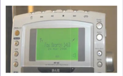
DRM has developed a system for digital signalling over AM transmissions. This system has been designed so that AMSS-equipped analogue transmissions can be identified, selected and tuned on hybrid analogue/DRM (or even analogue-only) radios, just as if they were digital services – see Figure 5.4. This greatly simplifies radio tuning and service selection for the listener and provides an extremely powerful and cost-effective facility during the migration of an audience from analogue to digital. In addition, the system supports alternative frequency signalling, such that a station equipped with AMSS can hand the listener’s receiver automatically to a digital, AM or FM simulcast transmission, as appropriate.
The system was engineered to be extremely robust whilst preserving excellent compatibility with existing AM receivers. The gross bit-rate is circ. 47b/s, and the system has been
successfully launched and tested on both MF and HF transmissions.
AMSS has now been published as ETSI standard TS 102 386 [4] and has been implemented in at least one first-generation DRM radio module. A description of the system, its features and implementation has been published by the EBU [5].
Figure 5.4: Screen-shot of DRM receiver in AM mode displaying AM service name
Advertisement
of
specialist
contact :[email protected] phone :+33 2 99 14 63 32 fax :+33 2 99 14 58 83
. Up to four services
. AAC+, CELP & HVXC audio encoding . Text Messages insertion
. Data insertion as option (MOT SLS & BWS, IP Tunneling etc.) . Management software through WEB . SNMP agent (MIB v2)
. SFN Ready . 1+1 redundancy
. All modes (A, B, C, D & E) and bandwidths
. IQ, Amplitude & Carrier, direct RF output types possibilities . Simulcast ready with spectral shaping (DRM30)
. SFN Ready
. Front Panel LCD for local settings . Management software through WEB . SNMP agent (MIB v2)
. Adaptive precorrection and delay adjustment
. Audio in RF out feature
DRM30
has never
been
so easy
!
DRM30/DRM+ AUDIO/CONTENT SERVER DRM30 MODUL ATOR/E XCITER DRM30/DRM+ MODULATOR/EXCITER with integrated audio encoder
o
of
specia
t
alis
actcont :[email protected] phone :+33 2 99 14 63 32 fax :+33 3 2 99 14 58 83
MORE
+1.902.823.5131 www.nautel.com/drm
Making Digital Radio Work.
Nautel offers the most advanced DRM transmitters available today. Choose
from power outputs of 1 kW to 2000 kW MW and 300 W to 88 kW FM.
Available with integrated instrumentation, industry leading efficiency,
comprehensive web management and of course Nautel’s renowned reliability
and support. Expect more from Nautel. Learn more at
www.nautel.com/drm
NXSeries MW or LW 25 kW – 2 MW
90%
E F F I C I E N C Y * *NX100 and aboveMO
E
R
Nautel offers the m
NXSeries MW or L
anced DRM transmitters av
most adv
W 25 kW – 2 MW
L
LW 25 kW – 2 MW
tters availab
*
0%
N C Y E E F F I C I%
*9
Expect
and support.
comprehensive web
ailable with integ
Av
from power outputs
Nautel offers the m
Making Dig
X100 and above N *Learn more at
t more from Nautel.
b management and of course Nautel’
ind
grated instrumentation,
s of 1 kW to 2000 kW MW a
anced DRM transmitters av
most adv
.
Work
gital Radio
.nautel.com/drm
www
more at
s renowned reliability
se Nautel’
,
ustry leading efficiency
y,
and 300
tters av
wailab
W to 88 kW FM.
rm
bility
.nautel.com/drm www +1.902.823.51316
DRM Content
This section describes the various elements of the broadcast signal. It may broadly be described as ‘content’. This includes the following main elements:
1. mandatory meta-data which is an essential component of the DRM system. Examples include much of the data carried in the Fast Access and Service Description channels (FAC/SDC)
2. non-mandatory information which a broadcaster may chose to include and which is automatically supported by receivers (e.g. text messages)
3. the audio content (radio services): both encoding and audio quality considerations 4. any value-added and/or data services which broadcasters may chose to implement
It should be noted that whilst ‘1’, ‘2’ and ‘3’ above will automatically be supported by any receiver which meets the relevant DRM specifications (Annex 3 and [6]), broadcasters should work closely with the receiver industry to ensure that support for any additional features (‘4.’ above) is properly integrated into consumer radios. See Section 7 − DRM Receivers for more information.
6.1 Broadcast meta-data
In this section, data that is mandatory is indicated by appending ‘{M}’ to the sub-heading. 6.1.1 Service ID {M}
The DRM Service ID is a worldwide unique identifier assigned to every DRM programme. It enables the AFS mechanism (Alternative Frequency Signalling) and allows a receiver to find and identify the selected programme even if its frequency has changed. It is not used by the listener for service or programme selection, nor is it shown on consumer receiver displays.
It is the broadcaster's responsibility to assign a unique ID to each of its DRM services. The DRM Service ID values are typically assigned by national authorities. More information on the format of the Service ID can be found on the DRM web site
6.1.2 Service Labelling {M}
The listener is informed about the tuned service by the name of the programme (DRM service label). The DRM service label is the primary programme identification and selection mechanism for the listener, while information about the current broadcast frequency or even the broadcast standard may not be disclosed at all by modern Digital Radio receivers.
The DRM service label can be any free text, up to 16 characters long. All worldwide scripts are supported for broadcast (up to 64 Label
Label
29
DRMIntroduction and Implementation Guide
6.1.3 Programme Type
The selection of a service can be made by the genre of the programme, for example news, rock music or drama. The figure above shows Pop Music and below
Finance/Business information, which could be information from the currency markets or stock exchange. DRM supports the optional signalling of 29 common programme types for audio services.
6.1.4 Service Language
The listener may be able select the language of the programmes he wants to receive on the radio. In regions with many languages, this might be helpful to avoid tuning into services that cannot be understood. DRM supports the optional signalling of all languages worldwide by using their respective ISO language codes.
6.1.5 Country of origin
The broadcast can optionally signal the country of origin for a particular DRM service. This information refers to the site of the studio, not a transmitter site. Thereby a receiver can enable the listener to scan for programmes originating from a particular country, for example to easily identify the national news programme whilst on vacation. All countries worldwide can be signalled by using their respective ISO country codes.
6.2 Audio content
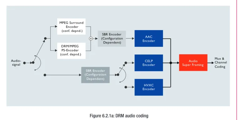
6.2.1 Audio Coding
In order to allow a trade-off between audio quality and number of services, the DRM system makes provision for three MPEG4 audio codecs (shown in Figure 6.2.1a). They vary in their field of application and bit rate
requirements. AAC provides the highest quality, whilst CELP and HVXC require progressively lower bit rates but are designed for speech-only services. In practice only AAC has been implemented saving on equipment
complexity and cost. The performance of all three codec’s can be enhanced by the optional use of SBR (Spectral Band Replication) coding.
Label Label
Figure 6.1.3: Programme Type (‘Finance/Business’)
Label Label
The enhancements of CELP and HVXC with SBR are specific to DRM audio coding. All three encoders can operate over a range of bit rates, and consequently support a range of programme content − see Figure 6.2.1b below and the DRM standard [1].
In the 18/20 kHz DRM30 modes and DRM+ mode, the available data rate allows the possible use of MPEG 4 stereo-compatible 5.1 surround sound broadcasts.
• AAC (Advanced Audio Coder) provides the highest quality at higher bit-rates. This codec can be used to code in mono, Parametric Stereo or full stereo modes, and is closely related to the audio coding used for the iTunes service.
• The CELP4(Code Excited Linear Prediction) Coder and HVXC (Harmonic Vector Excitation Coding) are
designed for mono speech-only applications. The bit rate can be down to 2 kbit/s with HVXC or 4 kbit/s for CELP. The performance of all three Codecs can be enhanced by the optional use of the SBR (Spectral Band Replication) tool, which requires an additional bit rate of around 2 kbit/s.
Figure 6.2.1b provides an indication of the operating ranges of the various coders set against the bit-rate capacity of some of the most common DRM modes.