6
I
January 2018
Hall Effects on the Flow of an Ionized Gas between
a Parallel Flat Wall and a long Wavy Wall
L.M. Vishnupriya1, S. Sreenadh2,
1
Department of Applied Mathematics, Sri Padmavathi Mahila Visva Vidyalayam, Tirupati – A.P, India 2
Department of Mathematics, Sri Venkateswara University, Tirupati – A.P, India
Abstract: Hall effects on the hydro magnetic flow of an ionized gas between a parallel flat wall and a long wavy wall have been studied. The analytical solution has been derived for velocity distribution. When the amplitude parameter
and the frequency parameter
are taken as zero, the results deduced agree with the corresponding of Sato [8]. The effects of Hartmann number M, Hall parameter m, amplitude parameter
on primary and secondary velocity distributions are presented graphically. It is observed that the primary and secondary velocities decrease with an increase in Hartmann number M in both partially and fully ionized cases. It is also observed that the effect of the amplitude parameters
is to increase both the primary and secondary velocities in both partially and fully ionized cases.Keywords: Hall currents, MHD, Ionized Gas, Plasma, Wavy wall,.
I. INTRODUCTION
Viscous fluid flow bounded by a wavy wall has attracted the attention of relatively few researchers although the analysis of such flows finds application in different areas such as transpiration cooling of reentry vehicles and rocket boosters, cross-hatching on ablative surfaces and film vaporization in combustion chambers. In view of these various applications, Lekoudis , Nayfeh and Saric [1] have made a linear analysis of compressible boundary layer flows over a way wall. Shankar and Sinha [2] have made a detailed study of the Rayleigh problem for a wavy wall and arrived at certain interesting conclusions, namely that at low Reynolds numbers, the waviness of the wall quickly ceases to be of importance as the liquid is dragged along by the wall, while at large Reynolds numbers the effects of viscosity are confined to a thin layer close to the wall and the known potential solution emerges in time. Vajravelu and Shastri [3] have devoted attention to the effect of waviness of one of the walls on the flow and heat transfer characteristics of an incompressible viscous fluid confined between two long vertical walls and set in motion by a difference in the wall temperatures. Lessen and Gangwani [4] have made a very interesting analysis of the effect of small amplitude wall waviness upon the stability of the boundary layer. Bhaskara Reddy and Bathaiah [5] have investigated the MHD flow of a viscous incompressible fluid between a parallel flat wall and a long wavy wall.MHD is the science of motion of electrically conducting fluid in the presence of magnetic field. Engineers apply MHD principle in fusion reactors, dispersion of metals, metallurgy, design of MHD pumps, MHD generators and MHD flow meters etc. MHD has important applications in biomedical engineering including cardiac, MRI and ECG. The principles of MHD are also used in stabilizing a flow against the transition from laminar to turbulent flow. Ionized gas is plasma which is the fourth state of matter. Plasma is a matter that starts as a gas and then becomes ionized. Ionization refers to the process whereby an atom or molecule loses an electron, resulting in two oppositely charged particles, a negatively charged electron and a positively charged ion. The degree of ionization refers to the proportion of neutral particles, such as those in a gas or aqueous solution that are ionized into charged particles. A low degree of ionization is sometimes called partially ionized, and a very high degree of ionization is termed as fully ionized.
Ahdanov [6] and Soo [7] studied transport phenomena in partially Ionized gases. The effects of hall currents in the viscous flow of an ionized gas between two parallel walls, under the action of a uniform transverse magnetic field are first studied by Sato [8] . Following this analysis, Raju and Rao [9] have studied the hall effects on temperature distribution in a rotating ionized hydromagnetic flow between parallel walls.
channel lined with non-erodible porous material on both the plates. In view of these several applications, it is interesting to study the flow of ionized gas between a parallel flat wall and a long wavy wall. The aim of the present paper is to study the combined effects of Hartmann number M, Hall parameter m and amplitude parameter
on the steady MHD flow of an ionized gas between a parallel flat wall and a long wavy wall for partially and fully ionized cases. The results are discussed through graphs.II. MATHEMATICAL FORMULATION OF THE PROB LEM
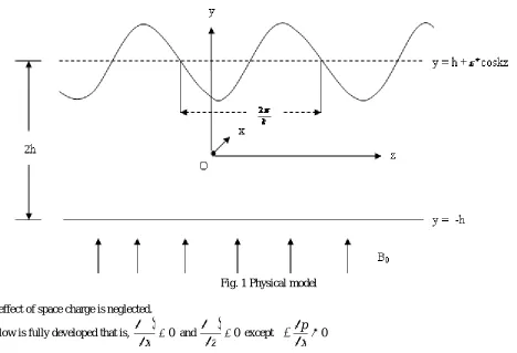
Consider the channel shown in figure 1, in which the z-axis is taken along the parallel flat wall and a straight line perpendicular to
that as the y-axis, so that the wavy wall is represented by
y
h
cos
kz
and the flat wall by yh. The height of the channel is denoted by 2h and the width is assumed to be very large in comparison with the channel height 2h. We asuume that the wavelength of the wavy wall which is proportional to
k
1
is large.
The x-axis is taken in the direction of hydrodynamic pressure gradient in the plane parallel to the channel walls, but not in the direction of flow. The fluid flow is along y-direction. A parallel uniform magnetic field B0 is applied in the y-direction and the Hall
currents are taken into account while, the fluid is driven by a constant pressure gradient
x p
. All physical quantities except
pressure become functions of y only, as the walls are infinite in extent along x- and z-directions. Further to simplify the theoretical analysis, the following assumptions in Sato [8], Raju and Rao [9] are considered :
The density of gas is everywhere constant.
[image:3.612.63.531.342.661.2]The ionization is in equilibrium which is not affected by the applied electric and magnetic fields
Fig. 1 Physical model
.The effect of space charge is neglected.
The flow is fully developed that is,
0
x and
0
z except 0
x p
The magnetic Reynolds number is small. The induced magnetic field is small when compared with the applied field. Therefore, components in the conductivity tensor are in terms of B0.
The flow is “two-dimensional”, namely
0
The physical configuration and the nature of the flow suggest the following forms of velocity vector q , the magnetic flux density
B, the electric field E and the current density J :
] , 0 ,
[u w
q ,
B
[
0
,
B
0,
0
]
,E
[
E
x,
0
,
E
z]
,J
[
j
x,
0
,
j
z]
In view of the above assumptions, the governing equations of motion reduce to
01
1 2 0 1 0 2 0
2 0
1
B E uB E wB
dy u d x
p
s z x
(1)
1 0 2 0
00 2 2
0
2
uB E wB E B dy w d x p
s
x
z
(2)
in which
s
p
ep
is the ratio of the electron pressure to the total pressure. The value of s is 0.5 for neutral fully-ionized plasmaand approximately zero for a weakly-ionized gas. u, w and
E
x,
E
z are x- and z- components of velocity q and electric field Erespectively.
Nomenclature
u, w Velocity components along x and z- directions.
q Velocity vector.
B The magnetic flux density.
E The electric field.
J The current density.
p Pressure.
Ex, Ez Electric fields along x and z-directions.
s =
p pe
Ionization parameter (the ratio of the electron pressure to the total pressure)
0 The coefficient of proportionality between the current density J and collision
term in the equation of motion of charged particles.
1, 2 The modified conductivities parallel and norma l to the direction of electric field.
2
.h x p up
Characteristic velocity.
m = 1 1 e e w Hall parameter.
we The gyration frequency of electron.
, e The mean collision time between electron, ion and electron, neutral particles
respectively.
amplitude parameter.kh
frequency parameter.
M= 0 2 2 0h B Hartmann Number.
Coefficient of viscosity (= )
Density of the fluid.
2 0 1
1m
; 2 0 21 m m
; e e w m
1 1The boundary conditions are
0
u
,w
0
aty
h
(3)0
u
,w
0
aty
h
*cos
kz
(4)We introduce the following non-dimensional variables and parameters .
,
*p
u
u
u
*,
p
u
w
w
*,
h
y
y
* ,h x
x * ,
h z
z ,
*
h
kh,
, . 2 h x p
up
0 ,
2 2 0 2 h B
M ,
0 p x x u B E
m ,
0 p z z u B E m , 1 1 2 0 1 m 2 0 2 1 m m 2 1 1 1 1 1 m s L 2 2 1 m sm L
In view of the above dimensionless quantities, equations (1) to (4) take the following form :
Neglecting the asterisks (*), we get,
2
00 2 2 0 1 2 2
1 M m u M m w dy
u d
L z x
(5)
2
00 2 2 0 1 2 2
2 M m w M m u dy
w d
L x z
(6)
The corresponding boundary conditions are
0
u
,w
0
at y1(7)0
u
,w
0
at y1
cos
z (8)For simplicity, we introduce the complex notations as
z x
im
m
E
iL
L
L
iw
u
q
,
1
2,
Equations (5) and (6) can be written in complex form as
E M E M i L q M i M dy q d 2 0 2 2 0 1 2 0 2 2 0 1 2 2
(9)
III. SOLUTION OF THE PROBLEM
If the side walls are made up of conducting material and short circuited by an external conductor, the induced electric current flows out of the channel. In this case no electric potential exists between the side walls. If we assume zero electric field also in the x- and z- directions, then mx = 0, mz= 0. In this case equation (9) becomes
2 2 1
1 m
M a
,
2 2 2
1 m
mM a
2 1
ia
a
a
Solving equation (10) subject to the boundary conditions (7) and (8), the expression for qis obtained as follows :
q A1cosha3ycosa4yA2sinha3ysina4y A3sinha3ycosa4yA4cosha3ysina4y f6
A1sinha3ysina4y A2cosha3ycosa4y A3cosha3ysina4y A4sinha3ycosa4y g6
i
(11)
Expanding real and imaginary parts, we get solutions for u and w. They all are dependent on s. The value of s is 0.5 for neutral fully-ionized gas and s = 0 for a weakly ionized gas. The primary and the secondary velocities (u and w) are obtained as follows:
A1cosha3ycosa4y A2sinha3ysina4y A3sinha3ycosa4y A4cosha3ysina4y f6
u
(12)
) cos
sinh sin
cosh cos
cosh sin
sinh
(A1 a3y a4y A2 a3y a4y A3 a3y a4y A4 a3y a4y g6
w (13)
We note that when amplitude parameter
0
and frequency parameter
0
, the results coincide with those of Sato [8].IV. RESULTS AND DISCUSSION
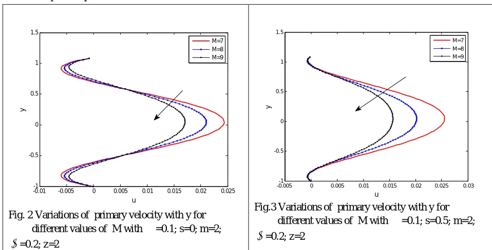
The closed form solutions for both the velocity distributions, such as primary velocity (u) and secondary velocity (w) distributions in the wavy wall channel are obtained. The results are depicted graphically in figures 2 to 13. The graphs are given for two cases, viz., partially ionized (s = 0) and fully ionized (s=0.5) cases.
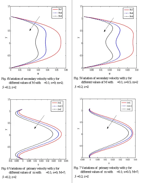
Figs. 2 to 5 show the variation in primary and secondary velocities for different values of Hartmann number M and for fixed m , ,
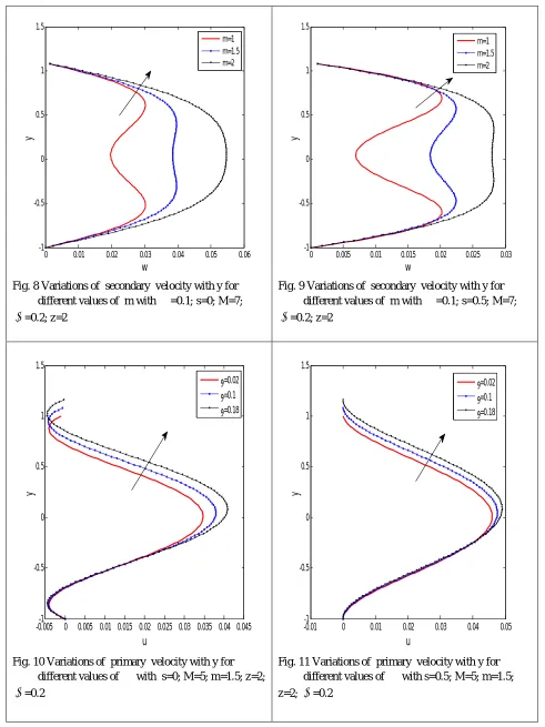
andz. It is observed that for partially and fully ionized cases, primary and secondary velocities decrease with an increase in the Hartmann number M. This is because the increase in the magnetic field gives rise to reduction in velocity in the channel.Figs. 6 to 9 show the variation in primary and secondary velocities for different values of Hall parameter m and for fixed M , ,
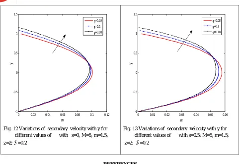
and z. It is observed that the primary velocity decreases with an increase in the Hall parameter m, whereas, the secondary velocity increases with an increase in the Hall parameter m.Figs. 10 to 13 show the variation in primary and secondary velocities for different values of amplitude parameter
and for fixedM, m,
andz. It is observed that for both partially and fully ionized cases, primary and secondary velocities increase with an increase in the amplitude parameter
.Fig. 2 Variations of primary velocity with y for different values of M with
=0.1; s=0; m=2; [image:6.612.64.543.456.700.2]
=0.2; z=2Fig.3 Variations of primary velocity with y for different values of M with
=0.1; s=0.5; m=2;
=0.2; z=2-0.01-1 -0.005 0 0.005 0.01 0.015 0.02 0.025 -0.5
0 0.5 1 1.5
y
u
M=7 M=8 M=9
-0.005-1 0 0.005 0.01 0.015 0.02 0.025 0.03 -0.5
0 0.5 1 1.5
y
u
Fig. 4Variation of secondary velocity with y for different values of M with
=0.1; s=0; m=2;
=0.2; z=2Fig. 6 Variations of primary velocity with y for different values of m with
=0.1; s=0; M=7; [image:7.612.68.544.89.693.2]
=0.2; z=2Fig. 5Variation of secondary velocity with y for different values of M with
=0.1; s=0.5; m=2
=0.2; z=2Fig. 7 Variations of primary velocity with y for different values of m with
=0.1; s=0.5; M=7;
=0.2; z=20 0.01 0.02 0.03 0.04 0.05 0.06
-1 -0.5 0 0.5 1 1.5
y
w
M=7 M=8 M=9
-0.01 -0.005-1 0 0.005 0.01 0.015 0.02 0.025 0.03 0.035
-0.5 0 0.5 1 1.5
y
u
m=1
m=1.5 m=2
0 0.005 0.01 0.015 0.02 0.025 0.03
-1 -0.5 0 0.5 1 1.5
y
w
M=7 M=8 M=9
-0.005-1 0 0.005 0.01 0.015 0.02 0.025 0.03
-0.5 0 0.5 1 1.5
y
u
Fig. 8 Variations of secondary velocity with y for different values of m with
=0.1; s=0; M=7;
=0.2; z=2Fig. 9 Variations of secondary velocity with y for different values of m with
=0.1; s=0.5; M=7;
=0.2; z=2Fig. 10 Variations of primary velocity with y for different values of
with s=0; M=5; m=1.5; z=2;
=0.2Fig. 11 Variations of primary velocity with y for different values of
with s=0.5; M=5; m=1.5; z=2;
=0.20 0.01 0.02 0.03 0.04 0.05 0.06
-1 -0.5 0 0.5 1 1.5
y
w
m=1
m=1.5 m=2
0 0.005 0.01 0.015 0.02 0.025 0.03
-1 -0.5 0 0.5 1 1.5
y
w
m=1
m=1.5 m=2
-0.005-1 0 0.005 0.01 0.015 0.02 0.025 0.03 0.035 0.04 0.045
-0.5 0 0.5 1 1.5
y
u
=0.02
=0.1
=0.18
-0.01-1 0 0.01 0.02 0.03 0.04 0.05
-0.5 0 0.5 1 1.5
y
u
=0.02
=0.1
Fig. 12 Variations of secondary velocity with y for different values of
with s=0; M=5; m=1.5; z=2;
=0.2Fig. 13 Variations of secondary velocity with y for different values of
with s=0.5; M=5; m=1.5; z=2;
=0.2REFERENCES
[1] Lekoudis SG, Nayfeh AH and Saric W S, “Linear analysis of compressible boundary layer flows over a wavy Wall”, Phys. Fluids., 1976, 19, pp. 514. [2] Shankar PN and Sinha UN, “Rayleigh problem for a wavy wall”,J. Fluid Mech.,1976, 77, pp. 243.
[3] Vajravelu K and Sastri KS , “Free convective heat transfer in a viscous incompressible fluid confined between a long vertical wavy and a parallel flat wall”, J. Fluid Mech, 1978, 86, pp. 365.
[4] Lessen M, Gangwani ST, “The effect of small amplitude wall waviness upon the stability of the laminarboundary layer”., Phys. Fluids., 1976, 19, pp. 510. [5] Bhaskara Reddy N and Bataiah D, “Magnetohydrodynamic flow of a viscous incompressible fluid between a parallel flatwall and a long wavy wall”, Def Sci.
J, 1981, 31, pp. 315-322.
[6] Ahdanov VM, “Transport Phenomena in a Partly Ionized gas”, PMM, 1962, 26, pp. 280-288.
[7] Soo, SL and Bahadori MN, “Non-Equilibrium Transport Phenomena of Partially Ionized Argon”, Int. J. of Heat Mass Transfer, 1965, 9,pp. 17-34.
[8] Sato H, “The Hall effects in the viscous flow of ionized gas between parallel plates undertransverse magneticfield”, J. Phys. Soc. Japan,1961, 16, pp. 1427-1433.
[9] Raju LT and Rao RVV, “Hall effects on temperature distribution in a Rotating Ionized Hydromagneticflow between parallel walls”, Int. J.Eng. Sci.,1993, 31(7), pp. 1073-1091.
[10] Yamanishi T, “Hall effects on hydromagnetic flow between two parallel plates”, Phy. Soc., Japan, Osaka,1962, 5, pp. 29.
[11] Ramadevi A, Sreenadh S and Ramesh Babu V, “Effects of Hall currents on hydromagnetic flow of an ionized gas between parallel porous walls through a porous medium”, Int. J. Math. Arc.,2012, 12, 4980-4988.
[12] Raju LT and Gowri Sankara Rao V, “Unsteady hydromagnetic flow of an ionized gas between parallel porous plates with Hall currents”, Advances in applied Science Research, 2013, 4, pp. 360-370.
[13] rotating system”, Int. J. Eng. Res. and Tech., 2013, 2, pp. 1316-1333.
[14] Ramadevi A, Sreenadh S, Ramesh Babu V, Sudhakara E, “MHD flow of an ionized gas in a parallel plate channel with porous lining”, Int. J. Math. Sci. & Engg. Appls., 2013 , 7, pp. 295-308.
[15] Sreenadh S, Vishnupriya LM and Ramadevi A, “MHD flow of an ionized gas in a parallel plate channellined with non-erodible porous material”, Int. J. Computer and Mathematical sciences, 2016, 5(1), 78-92.
0 0.02 0.04 0.06 0.08 0.1 0.12
-1 -0.5 0 0.5 1 1.5
y
w
=0.02
=0,1
=0.18
0 0.01 0.02 0.03 0.04 0.05 0.06
-1 -0.5 0 0.5 1 1.5
y
w
=0.08
=0.1