Efficient Fir Filter Implementation Based On
Minimum Logic Depth Tree
S.Romy Cathlane1, Ms. A.S Narmadaa2
1
PG Scholar, (VLSI Design), 2Assistant Professor/E.C.E Madha Engineering College, Kundrathur, Chennai – 600069
Abstract−Multiple constant multiplication (MCM) scheme is widely used for implementing direct-form FIR filters. While the research focus of MCM has been more effective on common sub expression elimination, the optimization of adder-trees, which sum up the computed sub-expressions for each coefficient, is largely omitted. This project provides a method to optimize the adder trees and thereby reducing the area. Canonical signed digit method is first used to optimize the adder tree. This method is compared with MIP optimization method. The problem is solved by assigning a binary tree for a single co-efficient and then by assigning the co-co-efficient value to the tree. Then overall minimization is carried out based on the Minimum Logic Depth Tree .This method is repeated for every iteration. The result shows 40% area reduction and 42% Dynamic Power Reduction. While the above methods reduce the area and power, speed is not taken care of. Hence the ripple carry adder used in the filter co-efficient is replaced by parallel prefix adder to reduce power and enhance speed. The result shows that speed is increased by 22%.
Index Terms −Adder-tree optimization, finite impulse response filter, FIR, MCM, CSD, multiple constant multiplication.
I. INTRODUCTION
FINITE IMPULSE RESPONSE (FIR) digital filters are widely used as a basic tool in many digital signal processing (DSP) and communication applications. The complexity of a FIR filter is largely dominated by the multiplication of input samples with filter coefficients. But fortunately, the filter coefficients are constants for a given filter, so that multiplications are implemented by a network of adders, subtractors, and hardwired shifts, where the number of adders and subtractors are minimized by a constant multiplication scheme. In case of a transposed direct-form FIR filter, the recent most input sample at any given clock period is multiplied with all the filter coefficients. A set of intermediate results are generated in this case, and shared across all the multiplications in order to minimize the total number of additions/subtractions using multiple constant multiplication (MCM) techniques. A great deal of research has been done to develop effective algorithms to identify the optimal set of non-redundant subex- pressions to achieve the minimum number of logic operators and the minimum logic depth of the MCM. Irrespective of differences in methodology and the level of optimality, in all these works, after the common subexpression terms are deter- mined and the ADD/SUB network of non-redundant subexpressions (or terms) is formed, the product value corresponding to each of the coefficients is computed by an adder-tree that sums up its relevant terms. Although many methods have been proved to reduce the number of additions and subtractions the adder tree is not optimized properly.So a new method is proposed in this paper optimize adder tree . Basically ripple carry adder is used in the adder tree structure. To enhance speed Parallel prefix adder is used.
II. CANONICAL SIGNED DIGIT
This section describes about the canonical signed digit method for reducing the number of adders and shifters used in the co-efficient to build up the adder tree. Canonical Signed Digit (CSD) representation of the filter coco-efficients can significantly reduce the complexity of the hardware implementation of digital FIR filters. It minimizes the area and power used. CSD has always been considered a fixed-point system, and available conversion algorithms operate on integers. Using methods applicable to many simple number systems, CSD for fractional numbers is rederived, deriving a simple floating-point recursion for converting fractions to CSD.
A. CSD Representation
182
tree.1) The number of non zero digits is minimal
2) No two consecutive digits are both non zero, that is, two non zero digits are not adjacent.
The first property implies a minimal Hamming weight, which leads to a reduction in the number of additions in arithmetic operations.
The second property provides its uniqueness characteristic.
However, if this property is relaxed, this representation is called the minimal signed digit(MSD) representation, which has as many non zeros as the CSD representation, but which provides multiple representations for a constant CSD representation has proven to be useful for the design and implementation of digital filters such as the area-efficient programmable.
B. Example
Binary --- 11111111
2^1+2^2+2^3+2^4+2^5+2^6+2^7+2^8 <<1+<<2+<<+3<<4+<<5+<<6<<7+<<8 CSD--- (1)000000(-1)
2^0 - 2^ = <<8
III. MINIMIUM RESOURCE BASED ON MIP METHOD
In this section, we describe a mixed integer programming (MIP) based formulation to schedule the adder-tree of an individual coefficient to minimize the hardware resource. As linearity is required in MIP, various techniques to transform modelling friendly non-linear expressions into linear equations and inequalities are indispensable and discussed in detail. This MIP procedure is then used in the next section as the building block for resource minimization for the entire FIR filter.
Given a set of input terms T={T0,...,TN-1} and their earliest arrival time or delay , we try to form an adder-tree of maximum
depth to sum up the input terms and at the same time minimize the hardware resource used.
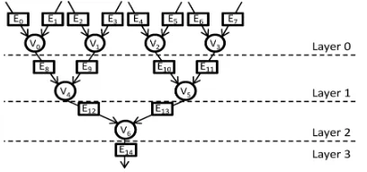
In order to model the above problem, we construct a complete binary tree G(V,E) of depth L. Each nodeVi € V on the tree is a
position to hold a binary operator (ADD/SUB), and |V|= 2L-1. Each edge Ei € E is a potential operand position to accommodate
[image:3.612.195.399.417.513.2]an input term, and |E| = 2L+1-1.
Fig. 1. Binary adder-tree of depth L=3 used for MIP modelling
Fig.1 shows an example of the decision tree when L=3 . An input term Ti of delay Di is schedulable on all edge positions of
layer Di and downwards.
For each input term, Ti we create a set of binary variables TSeti = {ti,j|Ej of depth equal or greater than Di} Ti is said to be
scheduled onEj if ti,j is assigned 1. The adder-tree scheduling problem is equivalent to finding an assignment of input terms to
the edge positions on the binary tree such that the resource of the adder-tree is minimized. Constraints are formulated to ensure that the adder-tree summing up these input terms is correctly formed.
A. Structural Constraints on Forming the Adder-Tree
Firstly, each input term should be scheduled exactly on edge position. For each input term , there is
∑∀ , ∈ t, =1
The next constraint ensures that no two input terms are assigned to dependent edge positions. On the binary tree Ej2, is
dependent on Ej1 if there exists a directed path from Ej1 to Ej2 .For example, E12 and E8 are both dependent on E0 ,while E12 is
Sum ETSetj1 + Sum ETSetj2 ≤ 1
Lastly, the number of ADD/SUB operators used for the summation of input terms totals to N-1. However, it is easier to compute the number of NULL operators on the binary tree. A NULL operator is an empty operator that is assigned neither an ADD nor a SUB in the end on the binary tree. It should be clear that if Ej is assigned any input term, all the operators which precede it on
the binary tree should be NULLs.
B. Constraints for the Type of Operators
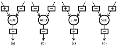
For a none NULL operator, its ADD/SUB type is determined by the simple rules. The number of operators on an adder-tree is determined by the number of input terms the coefficient uses from the term network On the binary decision tree, the types of each operator are determined by (1) the assignment of input terms which carry the original edge signs, and (2) the propagation of the signs throughout the network. There are two rules that are to be followed when assigning the operators. The following Fig 2 illustrates the relationship between the operator and the input
[image:4.612.192.390.229.314.2]
Fig 2 Relationship of Operator Type and The Output Sign With The Signs of Input Operands. The two rules are as follows:
(1) If two input edges are of the same sign, an ADD will be used; otherwise, it will be a SUB.
(2)The sign of the output edge is always the same as that of the “left” input edge (i.e., the minuend edge in the subtraction . Using these two rules, it is possible that the final term producing the summation result may carry a negative sign, such that a negation is needed after the adder-tree to correct the value .
C Constraints For Operator Cost
Edge Shifts
The shifts on the edges with a two step process by modeling the absolute shifts first, followed by the actual shifts. The absolute shift of a term (edge) within a coefficient is the shift of the LSB of the term against the LSB of the coefficient. Fig 3 gives an example of the absolute shift of each edge of a specific adder-tree of the coefficient. The absolute shift for an output edge simply takes the minimum value of that of its two input edges. Given that absolute shifts of all input terms are known constants for a coefficient, absolute shifts of intermediate terms on its possible adder-trees can be obtained by a top-down propagation process. Absolute shifts are modeled in a similar way that signs are modeled.
Fig 3 (a)Absolute Shift (b) Actual shifts
[image:4.612.170.393.525.645.2]184
Given the absolute shifts, the actual shifts are expressed in Fig 3(b)as follows. For a pair of input edges to the same operator,their common absolute shifts are trimmed off and taken care of by the output edge of the operator.
d. Cost of Structural Operators
For the sake of clarity, the structural operator(s) of the adder-tree are not modeled on the binary tree. In linear phase FIR filters, which are used in most cases, a coefficient is accumulated twice at symmetric tap positions, thus corresponding to two structural operators. In a general FIR filter, an adder-tree corresponds to one structural operator. For a structural operator, the adder-tree output edge always inputs to it as the right side operand, while the left input and output edges are on the accumulation line and their bit widths can be predetermined according to the upper/lower bound of accumulated values up to this coefficient tap. The left input edge is always “+” signed and carries 0 shift.
IV. RESOURCE MINIMIZATION FOR THE ENTIRE FIR FILTER
A top level algorithm to optimize the resource consumption of the entire FIR filter, based on the minimum resource of each individual coefficient returned by solving the MIP formulations discussed previously. The top level algorithm is based on the observation that logic depth relaxation on the coefficient may result in adder-tree of less resource. Without affecting the filter performance, logic depth relaxation is applicable to all the coefficients whose logic depths are smaller than the logic depth of the filter. first compute the minimum logic depth required by a coefficient adder-tree, and then apply logic depth relaxation to improve the minimum resource when applicable
1 compute the logic depth of the filter Lfilter
2 for each non-zero coefficient Cido
3 Compute Ci ’
s minimum logic depth of the filter LCi;
4 repeat
5 rsrc: MIPSched(Ci, LCi);
6 if rsrc is not improved over the previous iteration then
7 use the previous adder – tree schedule and break;
LCi = LCi+1;
8 Until LCi > Lfilter;
The algorithm for resource minimization of the entire FIR filter is elaborated in Algorithm. For a particular coefficient, the MIP based resource minimization procedure is first applied to yield an adder-tree schedule at its minimum logic depth (line5). Further logic depth relaxation is attempted provided that the current depth does not exceed that of the filter’s (line 8), and the current attempt did improve the minimum resource (line 6). At the end of the algorithm, each coefficient is resource minimized with its adder-tree schedule. The total resource of the entire filter is minimized, without increasing its overall logic depth. The above methods implemented using Ripple carry adder in the co-efficient tree. This paper is further extended to improve the speed of the adder. Parallel Prefix Adder is used to enhance speed.
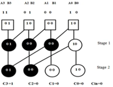
V. KOGGE STONE ADDER
operator. The KSA has the area (number of “o”operators) of (n*log2n)-n+1 where n is the number of input bit.
[image:6.612.212.396.99.241.2]
Fig 4 Parallel Prefix Adder
An example of a 4-bit Kogge–Stone adder is shown in Fig 4 . Each vertical stage produces a "propagate" and a "generate" bit, as shown. The culminating generate bits (the carries) are produced in the last stage (vertically), and these bits are XOR'd with the initial propagate after the input (the square boxes) to produce the sum bits.
VI. EXPERIMENTAL EVALUATIONS
[image:6.612.203.409.422.536.2]The given co-efficients of an FIR filter computed by MCM computation are converted using CSD method. It is compared with MIP method for area and power. Speed is increased by using parallel prefix adder. The following table shows the area and power comparison of the two methods and speed comparison of ripple carry and parallel prefix adder.
Table 1 : Comparison Of Area , Power And Speed Of The Two Methods
METHOD
AREA (No Of Logic Elements)
POWER mW
SPEED MHz
CSD 602 12.23
MIP
(RCA) 429 8.66 150.29
MIP
(PPA) 407 5.61 183.82
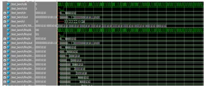
The following results shows the simulation waveform for all types of method simulated using Model Sim software.
[image:6.612.202.410.562.660.2]186
Figure 6 Simulation Waveform of MIP(RCA)Figure 7 Simulation Waveform Of MIP (PPA)
The above simulation waveform shows the simulation output for all the methods simulated using Model SIM
VII. CONCLUSION
MCM based filters consisting of shifters and adders are reduced occupy a considerable amount of area. Hence reducing the adders and shifters used helps reducing the area. CSD method reduces the area when compared to MCM method that can be proved manually. CSD method is then compared with MIP method for better optimization. The output results show that MIP method reduces 40% area utilisation and 42% Dynamic power consumed when compared to CSD method. Moreover replacing the Ripple Carry adder by parallel prefix adder enhances speed. The output computed using quartus tool shows that the speed is increased to about 22% using Parallel Prefix Adders when compared to Ripple Carry Adder.
REFERENCES
[1] Aksoy. L, Lazzari.C, Costa. E, Flores. P, and Monteiro. J, “Design of digit-serial FIR filters: Algorithms, architectures, and a CAD tool,” IEEE Trans. Very Large Scale Integration (VLSI) Syst., vol. 21, no. 3, pp. 498–511, Mar. 2013.
[2] Anshika Rajolia, Maninder Kaur. S Finite Impulse Response (FIR) Filter Design using Canonical Signed Digits (CSD).International Journal of Science and Research (IJSR), India Online ISSN: 2319-7064.
[3] Bull. D. R and Horrocks. D. H., “Primitive operator digital filter,” IEEE Proceedings-G, vol. 138, no. 3, pp. 401–412, Jun. 1991.
[4] Gustavo A.Ruiz n, MercedesGranda “Efficient canonic signed digit recoding” Departament of de Electro´nica and Computadores, Facultad de Ciencias, Avda.de Los Castross/ n,Universidad de Cantabria,39005 Santander,Spain.
[5] Hema Malini.A Srimathi.c “Low Complexity Digit Serial Fir Filter By Multiple Constant Multiplication Algorithms” IJRET: International Journal of Research in Engineering and Technology eISSN: 2319-1163 | pISSN: 2321-7308.
[6] Harini Sharma.D, Addanki Purna Ramesh “Floating point multiplier using Canonical Signed Digit”International Journal of Advanced Research in Electronics and Communication Engineering (IJARECE) Volume 2, Issue 11, November 2013.
[7] Mahesh. R and Vinod. A, “A new common subexpression elimination algorithm for realizing low-complexity higher order digital filters,” IEEE Trans. Computer-Aided Design. Integr. Circuits Syst., vol. 27, no.2, pp. 217–229, 2008.
[8] Mehendale. S. D. S. M and Venkatesh. G, “Synthesis of multiplier-less FIR filters with minimum number of additions,” in Proc. IEEE ICCAD,1995. [9] Park. I. C and Kang. H. J, “Digital filter synthesis based on minimal signed digit representation,” in Proc. Design Autom. Conf. (DAC),2001.
[10] Sundar.S, Mohanraj. V, Shandeep. S. D, Subhasri. E, Deepika. P. “A new Common Subexpression Elimination Technique for reducing logic operators and logic depth in FIR filter design.”
[11] Vernalde.S, Pasˇko.R, Schaumont.P, Derudder.V, Member, IEEE, and Dˇ uracˇkov.D “A New Algorithm for Elimination of Common Subexpressions” ieee transactions on computer-aided design of integrated circuits and systems, vol. 18, no. 1, january 1999.