Optimization of Co-ordination Control of FACTS
Devices by Using Fuzzy Lead-Lag Controller
Anand Chandrashekaran1, Anbalagan.A2, Bibin Jose.J.S3
1,2,3
PG Scholar, Department of Electrical and Electronics Engineering, Anna University, Regional Centre, Coimbatore - 47
Abstract— Power system stability control is an important task in power system operation. Several factors, such as external disturbances or internal mechanical torques, may easily affect the power system stability. Hence, the structural control of electric power networks has recently attracted more attention. FACTS devices are used to dynamically adjust the network configuration to enhance steady-state performance as well as dynamic stability. FACTS devices provide series or shunt compensation, but they interfere with one another when they are made to work together in a power system, causing damping oscillations in the line. In this paper, Thyristor-controlled series capacitor (TCSC) and the Static VAR compensator (SVC) are used for improving the power system stability. A novel approach of designing a controller which adaptively determines the parameters of two controllers at each control step according to the deviations of generator rotor speeds of the power system is developed to reduce the damping oscillations. The parameters are estimated by using the generator speeds and the monotonous time consuming and inaccurate process of human calculations is avoided, which has been used is proved to be more accurate than the conventional approach thus providing active power flow regulation and reactive power compensation.
IndexTerms—Flexible AC transmission system (FACTS), fuzzy control, static VAR compensator (SVC), thyristor controlled series capacitor (TCSC).
I. INTRODUCTION
406
FACTS devices are used to enhance both voltage stability margin and reduce losses in the system. For the better utilization of existing power system the proper coordination of one FACTS devices or multi-FACTS controller is necessary.In this project, two FACTS devices namely the Thyristor-controlled series capacitor (TCSC) and the Static VAR compensator (SVC) are used for improving the power system stability. A novel approach of controlling these two devices simultaneously to reduce the damping oscillations has been developed. The controller used adaptively determines the parameters of two lead-lag controllers at each control step according to the deviations of generator rotor speeds of the power system. The parameters are estimated by using the generator speeds and the monotonous time consuming and inaccurate process of human calculations is avoided. This parameter estimation technique which has been used is proved to be more accurate than the conventional approach. The impact of individual FACTS controllers on control centre operations is not very significant. However, as multiple FACTS systems are added to a transmission system, it becomes necessary for the control activities to be integrated and centrally coordinated. This is to avoid unforeseen interactions between control operations in one area with that in another area.
A Thyristor-controlled series capacitor (TCSC) is made up of a Thyristor controlled reactor in parallel with a fixed capacitor. Compared to TCR and SVC, TCSC is a series connected controller instead of a shunt-connected device. Hence, TCSC is always represented in single-phase form instead of three-phase form, and is always comprised of one or more sub-modules. TCSC changes the electrical length of the existing transmission line with negligible delay. This characteristic makes TCSC be used to perform the fast active power flow regulation. But adding TCSC into the existing system will change the phase angle of the buses. The Static VAR compensator (SVC) typically consists of a Thyristor-Controlled Reactor in parallel with a capacitor bank, which acts as a shunt connected variable reactance. The SVC cannot only generate but also absorb reactive power. When system voltage is low, the SVC generates reactive power (SVC capacitive). When system voltage is high, it absorbs reactive power (SVC inductive). Thus in this project the TCSC and SVC are operated together in a power system and they are co-ordinated to operate together so as to provide both active power flow regulation and reactive power compensation. The model is developed, simulated and validated with results to show the operations of both the FACTS devices together in a same power system.
II. FLEXIBLEACTRANSMISSIONSYSTEMS
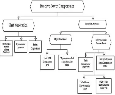
[image:3.612.212.401.438.594.2]FACTS is defined by ‘IEEE’ as power electronic based system and other static equipment that provide control of one or more AC transmission system parameters to enhance controllability and power transfer capability. The FACTS can be classified broadly into two main types. It is as follows:
Fig. 1Classification of FACTS devices
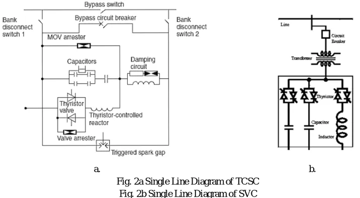
A.Thyristor Controlled Series Capacitor (TCSC)
a. b. Fig. 2a Single Line Diagram of TCSC
Fig. 2b Single Line Diagram of SVC
B.Static VAR Compensator (SVC)
The SVC regulates voltage at its terminals by controlling the amount of reactive power injected into or absorbed from the power system. When system voltage is low, the SVC generates reactive power (SVC capacitive). When system voltage is high, it absorbs reactive power (SVC inductive). An SVC can improve power system transmission and distribution performance in a number of ways. Installing an SVC at one or more suitable points in the network can increase transfer capability and reduce losses while maintaining a smooth voltage profile under different network conditions. The dynamic stability of the grid can also be improved, and active power oscillations mitigated.
III. MODELLINGOFTCSCANDSVC
A.Modelling of SVC
The SVC is a shunt device of the FACTS family using power electronics to control power flow and improve transient stability on power grids. The output of the compensator is controlled in steps by sequentially switching of TCRs and TSCs.By stepwise switching of reactors rather than continuous control, the need for harmonics filtering as part of the compensator scheme is eliminated. SVC application studies require appropriate power system models and study methods covering the particular problems to be solved by the SVC application.
[image:4.612.119.477.76.273.2]The parameters of the SVC have to be selected to SVC rating and performance criteria taking into account the power system behaviour under various operating conditions.
Table 1: Typical Parameters for SVC Models:
Module Parameters Definition Typical Value
Measuring Tm For Time Constant 0.001-0.005s
Thyristor Control
Td
Tb
Gating Delay Firing Delay
0.001s 0.003-0.006s Voltage
Regulator Ki Integrator Gain
Ki can be
adjusted
Slope XSL Steady-state error 0.01-0.05 p.u
1) Simplified Transfer Function of SVC: The system stability studies narrate how to get the substantial results by means of SVC to stabilize system voltages. For this situation the power system is represented by a source voltage in series with an equivalent system reactance Xe in p.u. Fig. 4 shows a simplified block diagram of the SVC with closed lope terminal
408
Fig.3 Simplified Transfer Function of SVCIn the simplified model:
H(s) = : transfer function of the voltage measuring device.
G (s) = : transfer function of voltage regulator and slope unit.
G (s) = : transfer function of compensator main circuit.
G (s) = X : transfer function of the network.
The slope of the steady-state characteristics is related to transfer function gain, K =
For simplified model, we have:
∆V (s) = G (s)G (s)G (s)
1 + G (s)G (s)G (s)H(s)∆V (s)
+ 1
1 + G (s)G (s)G (s)H(s)∆V (s)
2) Effects of location of SVC in transmission line: Location of an SVC strongly affects controllability of the swing modes. In general the best location is at a point where voltage swings are greatest. Normally, the mid-point of a transmission line between the two areas is a good candidate for placement. Thyristor Controlled Reactor (TCR): is a fixed reactor in series with bidirectional Thyristor valve. The amplitude of the TCR current can be changed continuously by varying the Thyristor firing angle from 90° to 180°. The TCR firing angle can be fully changed within one cycle of the fundamental frequency, thus providing smooth and fast control of reactive power supply to the system. Thyristor Switched Capacitor (TSC): comprises of a capacitor in series with bidirectional thyristor valve and a damping reactor, used to switch on and off the capacitor bank. The TSC can operate in coordination with the TCR so that the sum of the reactive power from the TSC and the TCR becomes linear.
B.Modelling of TCSC
A TCSC involves continuous-time dynamics, relating to voltages and currents in the capacitor and reactor, and nonlinear, discrete switching behaviour of thyristor. Deriving an appropriate model for such a controller is an intricate task. A TCSC model for transient and oscillatory-stability studies, used widely for its simplicity, is the variable-reactance model, the TCSC dynamics during power-swing other dynamics of the TCSC model, the variation of the TCSC response with different firing angles are neglected. It is assumed that the transmission system operates in a sinusoidal steady state, with the only dynamics associated with generators and PSS. This assumption is valid, because the line dynamics are much faster than the generator dynamics in the frequency range of 0.1-2Hz that are associated with angular-stability studies.The variable reactance TCSC model assumes the availability of a continuous-reactance range and is therefore applicable for multi-module TCSC configurations. This model is generally used for inter-area model analysis and provides high accuracy when the reactance-boost factor (XTCSC/Xc) is less than 1.5.
IV. RESULTS
A.Simulation of TCSC
The simulation of the TCSC is carried out by developing the transfer function model of the TCSC. The TCSC contains only one main block. The PID controller is used for controlling the output with the change in the input parameters. The output obtained is the Xtotal which is the total reactance.
[image:6.612.92.518.167.339.2]a. b. Fig. 5a Block Diagram of TCSC
Fig. 5b Simulation diagram of TCSC
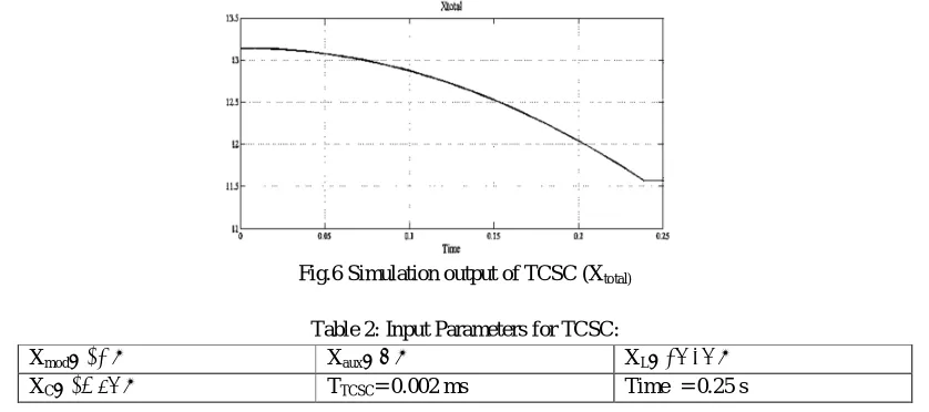
B.Simulation Output of the TCSC
The simulation of the TCSC is carried out in the MATLAB by developing the transfer function model as shown in the Figure 7 and the inputs are Xmod, Xaux, XL and XC. The output is obtained as shown in the Figure 8. The output depicts the value of Xtotal
which is the total net reactance. The values of the various input parameters are as follows:
Fig.6 Simulation output of TCSC (Xtotal)
Table 2: Input Parameters for TCSC:
Xmod= 12 Ω Xaux= 9 Ω XL= 28.38 Ω
XC= 15.68 Ω TTCSC= 0.002 ms Time = 0.25 s
C.Simulation of SVC
[image:6.612.96.515.399.585.2]410
a. b.Fig.7a Block diagram of SVC Fig. 7b Simulation diagram of SVC
D. Simulation output of the SVC
Thus the simulation of the SVC is carried out in the MATLAB by developing the transfer function model as shown in the Figure 10 and the inputs are Vt, Vref and Vaux. The output is obtained as shown in the Figure 11. The output depicts the value of
[image:7.612.96.512.271.441.2]Vt1 which is the terminal voltage. The values of the various input parameters are as follows:
Fig. 8 Simulation output of the SVC
Table 6.2: Input Parameters for SVC
Vt= 1.1 p.u Vref= 1 p.u Vaux= 0.67p.u Tm= 0.002ms
Tv1= 0.2ms Tv2= 0.02ms Tα= 0.004ms BLmax = 1
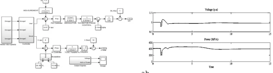
E. Simulation of Coordination Control of TCSC and SVC:
As shown above, the TCSC transfer function model and the SVC transfer function model have been modelled and simulated individually. Since the outputs of the SVC and the TCSC have been different parameters, we cannot combine these both as it is. Thus we require a generator rotor variation. Thus a real time power system is considered and the implementation of the SVC and the TCSC is obtained. The controller is designed for the purpose of modelling the outputs of the generator rotor speeds and analysing the current situation of the power system. When the fault occurs, the generator rotor speeds go out of synchronism. Thus the values are compared and the output Voltage and Power is shown in the output.
[image:7.612.72.525.564.686.2]a.b.
F. Simulation output of the Coordination control of TCSC and SVC
The outputs obtained are the voltage of the coordinated system and the power. The first graph indicates the output terminal voltage in per unit values. The second graph below indicates the power of the entire coordinated system. The fault occurs at the time t = 0.5s. This shows that the dynamic stability is achieved despite of large deviation in the rotor speeds of the generator which is caused because of the faults that occur in the power system. The generator rotor speeds block calculates the generator rotor speed that can be obtained from a multi-machine power system. The controller block controls the parameters of the input to the SVC and the TCSC by which a coordinated control can be obtained. The controller analyses the generator rotor speeds and the PID controller tunes the output with the obtained values of Vt, Vref, etc. The fault occurs at 0.5s and it is observed that
the voltage of the system is restored back to normal after quite some time. Thus the coordination control output is clearly obtained and the simulation diagram is shown in the Figure 12 and the output is shown in the Figure 13.
V. CONCLUSION
Thus the design of a controller which can control both the FACTS devices, Thyristor Controlled Series Capacitor (TCSC) and the Static VAR Compensator simultaneously was developed. The coordinated control of the two FACTS devices -Thyristor Controlled Series Capacitor (TCSC) and the Static VAR Compensator was successfully implemented. The TCSC and SVC was modelled individually and its results were observed and analysed. The coordination control of the FACTS devices requires analysing certain parameters. The generator rotor speeds is considered as the main parameter for obtaining the coordinated control of the TCSC and the SVC. The controller is designed such that the parameters are analysed on its own, instead of involving manual calculations which prove to be a maladroit technique. The development of the controller was carefully designed such that the damping inter-area oscillations are avoided. Thus the Coordination control of TCSC and SVC was achieved and theoretical and experimental results are presented to verify the new dispensation.
REFERENCES
[1] Y. Zhang and A. Bose (2008), “Design of wide area damping controllers for inter-area oscillations,” IEEE Transactions on Power Systems, Vol. 23, No. 3, pp. 1136–1143, August 2008.
[2] Alisha Bangla and S.S. Kaushik (2011), “Modelling and Simulation of SVC controller for enhancement of Power System Stability”, International Journal of Advances in Engineering & Technology.
[3] A.N.Tiwari, Bindeshwar Singh and N.K.Sharma (2013), “Coordinated Control and Interactions between FACTS controllers in Multi-Machine Power System Environments”, the Fifteenth National Power Systems Conference (NPSC), IIT Bombay, December 2013.
[4] Chia-Hung Hsu, Chia-Fang Juaung and Chun-Fang Lu (2013), “Coordinated Control of Flexible AC Transmission System Devices Using an Evolutionary Fuzzy Lead-Lag Controller with Advanced Continuous Ant Colony Optimization”, IEEE Transactions on Power Systems, Vol. 28, No. 1, February 2013.
[5] C. F. Juang (2011), “A hybrid of genetic algorithm and particle swarm optimization for recurrent network design,” IEEE Transactions on Power Systems, Vol. 34, No. 2, pp. 997–1006, April 2011.
[6] C. F. Juang and P. H. Chang (2010), “Designing fuzzy-rule-based systems using continuous ant-colony optimization,” IEEE Transactions on Fuzzy System, Vol. 18, No. 1, pp. 138–149, February 2010.
[7] C. F. Juang and C. F. Lu (2012), “Evolutionary fuzzy control of flexible AC transmission system,” Proc. Inst. Elect. Eng., Generation, Transmission, Distribution, Vol. 152, no. 4, pp. 441–448, July 2012.
[8] C. Y. Chung, K. W. Wang, C. T. Tse, X. Y. Bian, and A. K. David (2012), “Probabilistic Eigen value Sensitivity Analysis and PSS Design in Multi-machine Power Systems,” IEEE Transactions on Power Systems, Vol.18, No. 4, November 2012.