5
IX
September 2017
Shape and Size Effects on the Compressive
Strength of Stabilized Rammed Earth Both In Wet
and Dry Condition
Dr. Mahantesh M. Hanamasagar1, Keshavaraj Girinivas2,
1
Associate Professor, 2Research Scholar, Civil Engineering Department, Basaveshwar Engineering College-Bagalkot
Abstract- In this study we investigate the influence of shape and size of the specimens on the compressive strength of the rammed earth. We use cylinders and cubes for various sizes for performing stable stress – strain test. Rammed earth is simple to construct, non-combustible, thermally massive, strong and durable. However, structure such as walls can be labour - intensive to construct without protected or maintained. In order to gain deeper understanding of the additional causes influence the strength of rammed earth samples. Investigation on specimen slenderness, size, shape and capping methods has been also conducted. In the study carried out index properties of soil and classified the soil category. We are studying compressive strength of rammed earth using various sizes of cylinders and cubes.
Keywords: Cement stabilized Rammed Earth, Compressive strength, split tensile strength.
I. INTRODUCTION
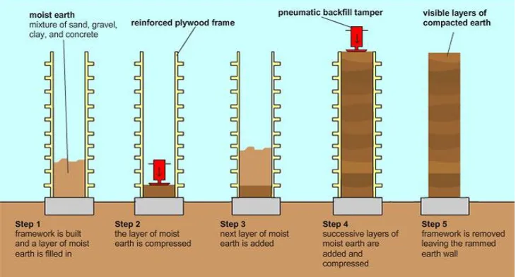
Rammed earth walls are formed by compacting wet soil in a rigid form work. It is a form of unbaked earthen construction used to build walls. Rammed earths are formed by process of packing wet soil particles closer by removing air voids through manual or mechanical means in progressive layers in a rigid form work. Large quantity of natural materials traditionally used in the construction of buildings and other similar civil engineering structures. The materials are prepared to their optimum moisture content and compacted inside a temporary rigid formwork to form walls. The earth composition varies greatly and always contains clay but should not include any organic components.
Clay acts as the binder between the grains, a mixture of silt, sand and gravel. [1]
The rammed earth wall is composed of several layers of earth. The earth is poured loose in layers about 10–15 cm thick into a timber or metal formwork, which is then rammed with a rammer (manual or pneumatic). After compaction, the thickness of each layer is typically 6–10 cm. The procedure is repeated until completion of the wall. Once the soil has been adequately compacted the form work is removed. Often immediately after compaction, living the finished walls to dry out. Walls are typically 300-450 mm thick, but this can vary wildly according to design requirements. In general, soil for rammed earth should be well graded, containing gravel, sand, silt, clay fractions. Ideally the soil should have reasonably high sand and gravel content, with some silt and sufficient clay act as binder and assist soil compaction.
A. Advantages
1) Low energy intensity and low carbon emissions.
2) Materials used are recyclable and bulk of the materials is locally available within a short distance from construction site.
3) Rammed earth offers wide variety of textures and finishes.
4) Flexibility in plan form for the buildings.
Figure 1. Construction steps of rammed earth structure (www.courtesyiagram.com)
Figure 2 Construction of cement stabilized rammed earth building at Kerala. (www.inspirationgreen.com)
[image:3.612.122.490.300.433.2]In general, soil for rammed earth should be well graded, containing gravel, sand, silt, clay fractions. Ideally the soil should have reasonably high sand and gravel content, with some silt and sufficient clay act as binder. Suitable soils for rammed earth wall construction in general meet the below criteria.
Table 1 Criteria for choosing the soil for construction of rammed earth wall Sand and gravel content 45 to 80% ( by mass)
Silt content 10 to 35% ( by mass)
Clay content 5 to 20% ( by mass)
Plasticity index 2 to 30 ( liquid limit < 45)
Linear shrinkage Not more than 5%
Soluble salt content Less than 2% ( by mass) Organic matter content Less than 2% ( by mass)
Rammed earths are monolithic solid materials and have been used for the construction of load-bearing walls, non-load bearing walls, free standing of internal and external walls, floors sub-base material in airport runways, roadways, aprons, foundations and earthen bunds. Soil, sand, cement and water from the ingredients for the construction of cement stabilized rammed earth panels.
B. Objectives
1) To study the influence of shape of the CSRE specimen in compression both in wet and dry condition.
2) To study the influence of shape of the CSRE specimen in compression both in wet and dry condition.
II. EXPERIMENTALINVESTIGATION A. Materials used
1) Natural Soil: This study discusses about the materials used and the methodology followed in the present study. In this work natural soil is used and completely experimental methodology is followed for engineering properties. A brief introduction about the above materials and methodology is presented as follows.
[image:4.612.211.421.142.300.2]
Figure 3 Natural soil collected from Gaddankeri Tanda, Bagalkot district.
2) Cement: Type of cement used shall be 43 grade Ordinary Portland Cement conforming to IS: 12269 (2009) code is used to prepare the rammed earth samples.
3) Water: Portable water shall be used for preparing samples.
B. Determination of particle size distribution
The percentage of various sizes of particles in a given dry sample can be found out by the mechanical analysis which is performed in two stages, i.e. dry sieve analysis and hydrometer analysis. In this work particle size analyzed by wet sieve analysis method following as per IS: 2720 (Part 4) –1985.
C. Grain size analysis test results
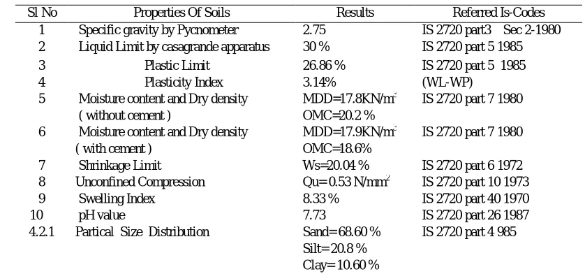
[image:4.612.133.474.454.718.2]Table 2 Properties of Natural Soil
1) Methodology
a) Steps involved in preparation of various sizes of CSRE cylinders, cubes and Material calculations
i) The dry soil is sieved through 4.75 mm sieve.
ii) The required materials are weight according to the calculation for density 17 kN/m3.
Figure 5 Weighed materials
iii) Then the soil is poured on a platform and levelled, spread thin layer of cement on the soil. iv) Then the materials are mixed manually in dry state.
[image:5.612.192.434.351.505.2]v) Again, the dry mix is mixed with calculated amount of water to get homogeneous mix
Figure 6 Homogenous mix
Sl No Properties Of Soils Results Referred Is-Codes
1 Specific gravity by Pycnometer 2.75 IS 2720 part3 Sec 2-1980
2 Liquid Limit by casagrande apparatus 30 % IS 2720 part 5 1985 3 Plastic Limit 26.86 % IS 2720 part 5 1985
4 Plasticity Index 3.14% (WL-WP)
5 Moisture content and Dry density ( without cement )
MDD=17.8KN/m3 OMC=20.2 %
IS 2720 part 7 1980
6 Moisture content and Dry density ( with cement )
MDD=17.9KN/m3 OMC=18.6%
IS 2720 part 7 1980
7 Shrinkage Limit Ws=20.04 % IS 2720 part 6 1972
8 Unconfined Compression Qu= 0.53 N/mm2 IS 2720 part 10 1973
9 Swelling Index 8.33 % IS 2720 part 40 1970
10 pH value 7.73 IS 2720 part 26 1987
4.2.1 Partical Size Distribution Sand= 68.60 % Silt= 20.8 % Clay= 10.60 %
Calculated amount of wet soil per layer is taken and placed in a mould.
Figure 7 Pouring wet soil per layer
vi) The loose soil is compacted with the help of rammer up to 1/3rdheight. The height of each layer is checked by using wooden logs.
Figure 8 Ramming wet soil using wooden logs Figure 9 Compacting wet soil with rammer
vii) •Thin layer of cement paste is applied to get better bond between successive layer. (figure 8)
viii) The same procedure is continued till the completion of third layer then it is levelled with the help of knife. ix) The specimens are demoulded after 24 hours of casting.
2) Curing
[image:6.612.116.497.292.441.2]The demoulded cube and cylindrical specimens are soaked in water for curing of 28 days.
3) Material calculation
Table 4 Material calculations for 17kN/m3various sizes of cubes and cylinders Where, CL= Cylinde, CB= Cube
Sl.No Shape Size Soil(Gm) Cement
(Gm)
Water (Gm)
Wet Soil Per Layer (Gm)
1 CL1 190mmx380mm 18000 1800 4356 7204.27
2 CL2 150mmx300mm 8500 850 6171 2057
3 CL3 100mmx200mm 2800 280 677.6 1050.34
4 CL4 32mmx76mm 120 12 29.04 40.87
5 CB1 150mmx150mmx150mm 5500 550 1331 2268.22
6 CB2 100mmx100mmx100mm 1500 150 363 668.66
7 CB3 70mmx70mmx70mm 600 60 145.2 229.35
8 CB4 50mmx50mmx50mm 230 23 55.66 83.58
III. TESTS CONDUCTED A. Experimental detail of Compressive strength
Compressive strength is conducted using different sizes such as:
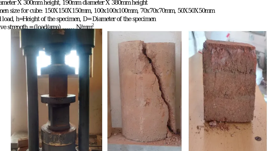
The specimen size for cylinder: 36mm diameter X 72mm height, 100mm diameter X 200mm height, 150mm diameter X 300mm height, 190mm diameter X 380mm height
The specimen size for cube: 150X150X150mm, 100x100x100mm, 70x70x70mm, 50X50X50mm P=Applied load, h=Height of the specimen, D= Diameter of the specimen
Compressive strength = (load/area) …… N/mm2
Figure 11 Compressive strength of CSRE specimens
B. Split Tensile Strength
After recording the mass and dimensions of the specimen the cylinder is mounted in displacement controlled testing machine as shown in Fig 4.7. The line load was applied through 10 mm * 10 mm square bar of 300 mm length mounted on diametrically opposite positions along the length of the cylinder. Based on the failure load split tensile strength was determined using the formula.
Ft=(2Pmax/ Dh) [1-ᵦ2](3/2)
Where, Ft=split tensile strength in MPa, Pmax=the maximum load in N, D=diameter of cylinder in mm, h=height of cylinder in mm ᵦ =The ratio of the width of distribution load to the diameter of the specimen.
[image:7.612.83.520.317.562.2]Figure 14 Schematic representation of Split strength test
[image:8.612.158.456.233.379.2]
Figure 15 Split tensile strength of CSRE specimens
C. Result and discussion.
Strength of CSRE are sensitive to moisture content of specimen during testing, as well as dry densities of the specimens therefore the CSRE specimens were tested under two extreme conditions of dry and wet conditions. Size and shape effect was compared and strength characteristics also compared and discussed below.
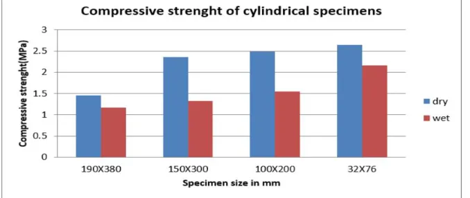
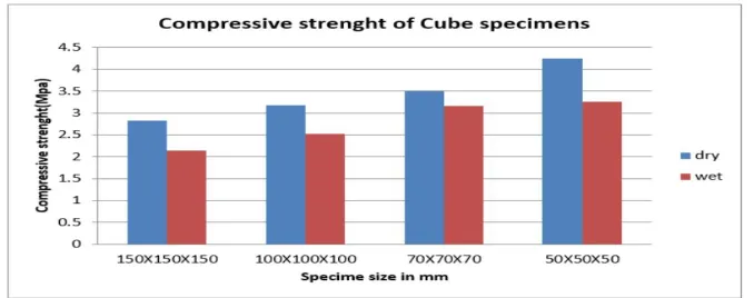
1) Compressive strength of CSRE: At 17kN/mm2the compressive strength of cylindrical specimen of 190mmx380mm is 1.46N/mm2& 1.17N/mm2, 150mmx300mm is 2.36N/mm2& 1.33N/mm2, 100mmx200mm is 2.49N/mm2& 1.55N/mm2, 32mmx76mm is 2.64N/mm2& 2.37N/mm2for both dry& wet conditions respectively. At 17kN/mm2 the compressive strength of cube specimen of 150mmx150mmx150mm is 2.83 N/mm2& 2.14 N/mm2, 100mmx100mmx100mm is 3.18 N/mm2& 2.53 N/mm2, 70mmx70mmx70mm is 3.5 N/mm2& 3.16 N/mm2, 50mmx50mmx50mm is 4.24 N/mm2& 3.20 N/mm2 for both dry& wet conditions respectively.
2) Split tensile strength of CSRE: At 17kN/mm2the split tensile strength of cylindrical specimens of size 150mmx300mm is 0.172N/mm2& 0.138N/mm2for both dry and wet conditions respectively.
[image:8.612.141.480.572.715.2]Figure 13 Comparison of compressive strength of CSRE cube specimens
IV. CONCLUSIONS
A. Test results show size effect. Large specimens resist less in terms of stress than the small ones. The size effect in the cubes is quite stronger than in cylinders.
B. The crack pattern observed after the test is sensitive to the shape of the specimen. A main inclined facture surface is nucleated in cylinders where as in cubes we found that the lateral sides get spalled and that there is fragmentation due to crushing and in several cases, a dense columnar cracking in the bulk of the specimen.
C. Cylinders broke in all cases by a diagonal fracture plain and cubes present a bursting rupture combined in some cases with a dense columnar cracking.
D. Compressive strength increases with decrease in specimen sizes.
E. Dry specimens give more strength than wet specimens.
V. ACKNOWLEDGMENT
We extremely happy to express our deep sense of gratitude and sincere thanks to our head of department Dr. M. S. Gadagi for giving opportunity to do experimental work in department, we would like to thank Dr. R. N. Herkal, principal Basaveshwar Engineering college Bagalkot for providing us the pleasant environment in the college. We also thanks support received from undergraduate students Uzma Muddebihal, Priyanka Angadi, Vishal Parasannavar, Vikaskumar. We wish to thanks post graduate student Sahana Antaratani for her support during the experimental work.
REFERENCES
[1] T-T Bui, Q-B Bui, A Liman, S.Maxmilien, Failure of rammed earth wall: From observation to quantification, Elsevier journal, Construction and Building Materials 51-2014 pp 295-302.
[2] Peter Walker, Rowland Keable, Joe Martin, Rammed earth: design and construction guidelines. BRE book shop Bucknalls.
[3] J.R.delviso, j.R.carmona, G Ruiz(2007). “Shape and Size effects on the compressive strength of high-strength concrete”. Journal, cement and concrete research 38(2008), pp 386-395.
[4] Vasiliousmaniatidis and peter walker (2008).“Structural capacity of rammed earth in compression”. Journalof materials in civil engineering, pp 230-238. [5] Givanildoazeredo, teanclaude morel and normandorerozzo Barbosa (2007). “Compressive strengthntesting of earth morters” journal of urban and
environmental engineering , V.I, n.i(2007) 26-35.
[6] P.A.jaquin, C.E.augarde, D Gallipoli and D.G.Toll(2009). “The strength of unsterilized rammed earth materials”. Journals,Geotechnique 59, no5, 487-490. [7] J.C,Moral, A Mesbah, M. Oggero, P. Walker(2000). “Building houses with local materials to drastically reduced the environmental impact of construction”.
Journal, Building and Environment 36(2001) 1119-1126.
[8] B.V.Venkataramareddy, P.Prasnnakumar(2011). “Part B: Compressive strength and stress-strain characteristics”.Journal, Materials and structures.
[9] Daniela Ciancio, Joshua Gibbings (2011). “Experimental investigation on the compressive strength of cored and molded cement-stabilized rammed earth samples”. Journal of construction and Building Materials 28 (2012)294-304.
[10] IS-12269(2009). Ordinary Portland Cement, 43 grade cement-Specification, Bureau of Indian Standards, New Delhi, India. [11] IS-code,IS-2720(Part-IV)1985, Methods of tests for soils-Part 4:Grain Size Analysis, Bureau of Indian standards, New- Delhi, India.
[12] IS-Code, IS-2720(Part V)1985, Methods of tests for soils- Part 5:Determination of Liquid and Plastic Limits, Bureau of Indian Standards, New-Delhi, India. [13] IS-Code, IS-2720(Part VII) 1985, Methods of tests for soils- Part 7: Determination of Water Content-Dry density using light compaction, Bureau of Indian
Standards, New-Delhi, India.
[14] IS-Code, IS-2720(Part 26) 1987, Methods of tests for soils- Part 26:Determination of pH value, Bureau of Indian Standards, New-Delhi, India. [15] www.greenspec.co.uk/.../rammed-earth