Multi-Objective Transmission Pricing Using
Mw-Mile Method
M.Divya1, V. Suma Deepthi2, 1, 2
Malla Reddy engineering College, EEE Department, Malla Reddy engineering College
Abstract: With regards to focused power markets, transmission settled expenses ought to be reasonably allotted to transmission clients. A sensible assignment technique could prompt effective uses of existing transmission offices and in the meantime, give financial signs to controlling future era arranging and load sitting. The proposed technique considers the active power flow in the network and power factor with loss cost and it is the first pricing strategy to consider the real network conditions and power flow in the network. MW mile method is a simple method useful to cover the total transmission system cost among all network users. The main objective of this paper is to provide cost economically to the customers by considering not only the active power flow but also the power factor with loss cost. The paper proposes the multi objective MW-Mile method which gives solution to transmission pricing with power factor and loss cost. The proposed technique is tested on IEEE-14 Bus system and it is simulated using MATLAB software.
Keywords: Cost allocation on transmission, MW method, MW power factor, loss calculation.
I. INTRODUCTION
The way that transmissions charges speak to a little level of working costs in utilities, the transmission arrange is an imperative system in aggressive power markets. In a rebuilt control framework, the transmission arranges is the place generators content to supply vast clients and appropriation organizations. Hence, transmission estimating ought to be a sensible monetary pointer utilized by the market to settle on choices on asset distribution, framework extension, and support.
The focused condition of power markets requires wide access to transmission and appropriation arranges that associate scattered clients and providers. Additionally, as power streams impact transmission charges, transmission evaluating may decide the privilege of section as well as energize efficiencies in control markets. For instance, transmission imperatives could keep an effective creating unit from being used. An appropriate transmission evaluating plan that considers transmission requirements or clogs could rouse speculators to construct new transmission as well as creating limit with respect to enhancing the effectiveness. In an aggressive situation, legitimate transmission estimating could meet income desires, advance a proficient operation of power markets, energize interest in ideal areas of era and transmission lines, and enough repay proprietors of transmission resources. Most critical, the valuing plan should execute decency and be functional.
In any case, it is hard to accomplish an effective transmission estimating plan that could fit all market structures in various areas. The continuous research on transmission valuing demonstrates that there is no summed up concurrence on evaluating procedure. By and by, every nation or each rebuilding model has picked a technique that depends on the specific qualities of its system. Measuring regardless of whether a specific transmission evaluating plan is in fact and monetarily sufficient would require extra guidelines.
A. Transmission Cost Designation Techniques
A proficient transmission valuing component ought to recuperate transmission costs by allotting the expenses to transmission arrange clients appropriately. The transmission expenses may include:
Running costs, for example, costs for operation, support, and auxiliary administrations. Past capital speculation.
Ongoing speculation for future development and support related to stack development and extra exchanges.
Running expenses are little contrasted and the capital speculation (or installed transmission costs). Subsequently, transmission charges for installed cost recuperation would to a great extent surpass running expenses over the venture recuperation period. The investigation destinations and market structures are primary variables for picking calculations in the assessment of transmission valuing. Despite the market structure, it is essential to precisely decide transmission use keeping in mind the end goal to execute utilization based cost portion strategies. In any case, deciding a precise transmission use could be troublesome because of the nonlinear idea of energy stream. This reality requires utilizing surmised models; affect ability lists, or following calculations to decide the commitments to the system streams from singular clients or exchanges.
1) MW-Mile Technique: The MW-mile technique is an implanted cost strategy that is otherwise called a line-by-line technique since it considers, in its figurines, changes in MW transmission stream and transmission line lengths in miles [Lim96, Pan00, Shi89, and Shi91]. The technique computes accuses related of each wheeling exchange in view of the transmission limit utilized as a component of the size of executed power, the way took after by executed power, and the separation went by executed power. The MW-mile technique is additionally utilized as a part of recognizing transmission ways for a power exchange. Thusly, this strategy requires dc control stream computations. The MW-mile technique is the principal valuing methodology proposed for the recuperation of settled transmission costs in view of the genuine utilization of transmission organize.
The strategy ensures the full recuperation of settled transmission costs and sensibly mirrors the genuine utilization of transmission frameworks. The accompanying calculation is utilized as a part of the MW-mile technique to appraise the use of firm transmission benefits by wheeling exchanges:
a) For every exchange t:
b) Use nodal control infusions engaged with exchange t, computer exchange related streams on all system lines utilizing a
surmised (dc) control stream demonstrate.
c) The size of MW stream on each line is duplicated by its length (in miles) and the cost per MW per unit length of the line (in
$/MW-mile) and summed over every one of the lines.
d) Repeat the procedure for different exchanges.
e) The commitment of exchange t to the aggregate transmission limit cost is ascertained as takes after Transmission office costs
are assigned to the extent to the proportion of stream size (outright esteem) contributed by exchange t and the whole of Supreme streams caused by all exchanges, as given by the condition.
TCt = TC
Where
TCt = Cost assigned to transaction t
TC = Cost of total lines in $
Lk = line length in K miles
Ck = Price per MW per length of line in units k
MWt,k = flow on line k caused by transaction t
T = no. of transactions K = no. of transmission lines
The magnitude of every line multiplies with the length of the line and price per MW per length in unit of a network of the transmission line. The main characteristic of the MW-Mile methodology is that we need to find out usage of each transaction on every individual branch. Based on this, there are various versions of MW-Mile approach.
The transmission cost utilizing MW mile strategy can be figured as
The power factor can be communicated as
The load with reactive power Q1 can be written as
Another power factor is obtained by expansion of responsive energy to the load, given as
The line current because of load included with responsive power Q2 can be composed as
Where
Where I is the line current and ΔI' is the adjustment in line current because of reactive power. Line misfortunes will be little when the line current is little. This will expand the transmission line conveying limit
C. Calculation of Proposed Technique
The genuine energy of load can be composed as
P=VI cos φ
This can likewise be composed as
Give us a chance to consider V as steady esteem and cosφ1 = cosφref. In this manner, the condition can be adjusted as
In this way the relationship is
Therefore,
This can be written as
By rewriting the equation, we get
If the transmission line’s resistance is constant then the power flow change ( ) is equivalent to current flow change. Therefore, equation (15) can be written as
is an additional power flow when load power factor less than reference power factor and P is the power flow of the line. The same calculation can be done to prove load power factor greater than reference power factor. This can be expressed as
where cos is the power factor of a load with load power factor>reference power factor
Now by substituting (17) in (1) we get
By substituting value in above equation
This condition can be reworked as
As a rule, we take as which is genuine estimation of energy factor In this manner, we get
This condition can be composed as
where, is the power factor remedy coefficient.
From the above condition, we can infer three conditions
Case 1 :
At the point when the genuine power factor is equivalent to reference control factor, the client pays the expense as indicated by the aggregate MW sum utilized.
Case 2:
The power factor remedy coefficient for this condition is
At the point when genuine power factor is not as much as reference control factor the client pays extra charges in light of the fact that the power factor redress coefficient is more prominent than 1
Case 3:
The power factor redress coefficient for this condition is
At the point when the genuine power factor is more prominent than reference control factor, the client pays lesser expenses. At last, the new MW mile strategy cost condition is
Where , C LF is controlling factor adjustment coefficient..
D. Mw power loss cost calculation
The equation of power handling capacity can be written as follows
(1)
Assuming unity power factor the current carrying capacity of the line can be calculated as follow
(2)
By substituting (1) in (2) we get
(3)
The power loss corresponding to the maximum power capability in a 3 phase system can be written as follows
(4)
By substituting (3) in (4) the expression for modifies to
(6)
Considering the stability mostly δ is limited to certain value hence by assuming the equation (6) can be re written as
follows
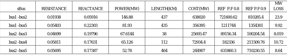
[image:7.612.35.593.188.296.2]
Table 1: Cost values of new proposed technique considering power factor and loss cost
sBus RESISTANCE REACTANCE POWER(MW) LENGTH(KM) COST(MW) REF P.F 0.8 REF P.F 0.9
MW LOSS
bus1 -bus2 0.01938 0.05916 146.88 437 638020 721600.62 810285.4 23.9
bus1 -bus5 0.05403 0.22303 81.93 435 356395 1211744 1354301 9.92
bus2 -bus3 0.04699 0.19796 67.6144 38 25693.47 89156.34 100204.54 8.019
bus2 -bus4 0.05811 0.17631 65.126 112 72934.4 182336 211509.76 10.72
II. RESULTS
: Fig1: IEEE-14 bus system
The proposed Techniques is implemented on IEEE -14 Bus system. It consists of generators on bus 1 and bus 2.and loads are at bus 2,bus 12, bus 13, bus 11, bus 5, bus 6, bus 10, bus 17, bus 3, bus 14, bus 4.The table 1 represents the cost values considering with power factor at0.8 and at 0.9 with Loss cost.
III.CONCLUSION
This MW method is the easiest method in transmission cost allocation system. This Paper demonstrates the outcomes for another calculation of MW mile technique with control power factor revision coefficient and with loss cost. This enables the reasonable portion of the cost to the clients by increasing the power factor. If the consumer improves power factor then there is a reduction in max demand and net annual savings for the customer as well as the generation side. The New technique Multi-objective MW-Mile method is to provide cost economically to the customers by considering not only the active power flow but also the power factor with loss cost and the results is shown in table1. The proposed technique is tested on IEEE-14 Bus system and results obtained with least cost.
REFERENCES
[1] Market operations in electric power systems, for casting, scheduling, and risk management by Mohammad shahid eh pour Hmit Yamin zuyi li
bus3 -bus4 0.06701 0.17102 -9.0747 6 544.2 1208.12 1360.5 1.77
bus4 -bus5 0.01335 0.04211 -55.0796 780 429620.9 489767.8 549914.72 8.73
bus4 -bus9 0 0.20911 36.8919 284 104767.6 0 0 0
bus5-bus6 0 0.55617 21.1681 284 60117.4 0 0 0
bus6 -bus11 0 0.25201 49.6398 188 93304.4 0 0 0
bus6 -bus12 0.9498 0.1989 7.2149 164 11824.4 205269.68 233261 1.72
bus6-bus13 0.12291 0.2558 9.5468 164 15656.75 29121 32877.6 2.2
bus7-bus8 0.06615 0.13026 26.1587 168 44618.62 7894.95 89237.2 6.74
bus7 -bus9 0 0.17614 0 164 0 0 0 0
bus9 -bus10 0 0.11001 36.8919 88 32464.8 0 0 0
bus9-bus14 0.03181 0.0844 6.3998 40 2559.6 5631.12 6399 1.2
bus10 -bus11 0.12711 0.27037 24.9406 40 9976.24 18954.85 21349 5.86
bus1 -bus18 0.08205 0.19206 -3.2739 40 1309.2 2618.4 2880.24 0.69
bus12 -bus13 0.22092 0.19987 3.2739 44 1642.9 1774.3 1971.4 2
[2] A Comprehensive Transmission Cost Allocation by Composite MW-mile & Composite MVA-mile Methods with Efficient ARR Babasaheb Kharbas, Manoj Fozdar, Harpal Tiwar
[3] Allocation of Transmission Line using a New Approach of MW Mile Method Monica Andukury1* and K.Sarada2
[4] D. Shirmohammadi, C. Rajagopalan, R. Eugene, A.Chifong, and L.Thomas, “Cost of transmission transactions: an introduction,” IEEE, Trans. on Power Syst., vol. 6 no. 4, pp.1546-1560, November 1991
[5] D. Shirmohammadi, X. V. Filho, B. Gorenstein and M.V.P. Pereira, “Some fundamental technical concepts about cost based transmission pricing,” IEEE Trans. on Power Syst., vol. 11 no. 2, pp.1002-1008, May 1996. J. W. Marangon Lima, “Allocation of transmission fixed charges: an overview,” IEEE Trans. on Power Syst., vol. 11 no. 3, pp.1409-1418, August 1996.
[6] Y. M. Park, J. B. Park, J. U. Lim, and J. R. Won, "An analytical approach for transaction costs allocation in the transmission system," IEEE Trans. on Power Syst., vol. 13 no. 4, pp. 1407-1412, November 1998.
[7] J. Pan, Y. Teklu, S. Rahman, and K. Jun, “Review of usage-based transmission cost allocation methods under open access,” IEEE Trans. on Power Syst., vol. 15 no. 4, pp.1218-1224, November 2000.
[8] Bialek J. Allocation of transmission supplementary charge to real and reactive loads.IEEE Transactions on Power Systems. 1998 Aug; 13(3):749–54. Bialek J. Allocation of transmission supplementary charge to real and reactive loads.IEEE Transactions on Power Systems. 1998 Aug; 13(3):749–54.