Xilinx System Generator
®
Based Implementation of a
Novel Method of Extraction of Nonstationary Sinusoids
Muhammad Abubakar, Arshad Aziz, Pervez Akhtar
Dept. of Electrical (Communication) Engineering, Pakistan Navy Engineering College National University of Sciences and Tech-nology, Islamabad, Pakistan.
Email: [email protected], [email protected], [email protected]
Received March, 2013.
ABSTRACT
Model based implementation of a novel nonlinear adaptive filter for extraction of time varying sinusoids using Xilinx system generator has been presented in this work. The practicality of this filter model along with its performance makes it one of the foremost candidates to be applied on nonlinear systems for the purpose of estimation and extraction using reconfigurable hardware like FPGA. A design implementation and verification approach has been discussed for more efficient implementation. Timing and power analysis has been performed and the architecture has been optimized for speed and power to perform at higher frequency when integrated on a Xilinx FPGA. The proposed hardware oriented architecture has been successfully implemented and simulated. The simulation results to track a noisy input have also been shown to demonstrate the exceptional performance of the hardware based architecture developed.
Keywords: Xilinx; System Generator; FPGA; Adaptive; Filter; Estimation; Sinusoid; Spatan6; Sta
1. Introduction
Field programmable gate array (FPGA) is the fastest growing emerging technology of present day and the need for reconfigurable and compatible design is in-creasing for system integration in present computation-ally expensive environments. Adaptive applications and systems are also widely used in the DSP and control sys-tems for unparalleled performance, so there is need to develop FPGA based adaptive algorithms to fulfill future demand. A versatile adaptive filter algorithm which is based upon nonlinear differential equations and tracks the amplitude, frequency and phase of the time varying input sine function [1-3] is taken as the base model and its fixed point hardware model has been created and suc-cessfully implemented using the schematic design envi-ronment of Xilinx System generator (XSG) [4]. VHDL\Verilog based programming and solution devel-opment is not desirable in most cases as the level of complexity involved is very great and a small mistake in the design can take even days of design time to debug, even if one succeeds in successfully implementing the design at hand it is still a big task to optimize the design to make it compatible with certain area or speed re-quirements. The Xilinx block set for system generator gives us a Simulink like schematic design environment to work in and create, convert, debug, optimize and imple-ment the DSP based designs easily and quickly onto the
desired FPGA device [5]. XSG has been successfully utilized in various domains including LMS adaptive fil-ters to design hardware oriented architectures to meet performance demands for systems [6]. Figure 1 shows the basic continuous time architecture for the filter, it has exceptional performance in nonlinear applications rele-vant to the mainstream nonlinear adaptive filter e.g. the extended Kalman filter (EKF) which makes it a suitable candidate for such applications and its simple structure is easy to understand and debug for performance related issues [2]. The discretized equations as used in the ex-perimental verification [7] have been taken and imple-mented on Simulink to create a reference model for the design on system generator. A module by module and block by block implementation was followed to imple-ment this design in system generator during which a number of implementation relevant design problems were faced and successfully solved. The final design was optimized to minimize the latency for critical path to get the results which make the design viable to implement on reconfigurable hardware to support the real-time applica-tions [8-10] and other time sensitive systems.
2. Previous Implementation
2.1. Computer SimulationsXilinx System Generator® Based Implementation of a Novel Method of Extraction of Nonstationary Sinusoids 8
Figure 1. Block diagram for the novel adaptive algorithm [2].
set of equations [7] which were implemented in Simulink to observe the tracking performance for the novel method. Equations (1-5) give the estimates for tracked amplitude, tracked frequency, tracked phase, tracked output and estimation error.
A[n+1] =A[n] +2Tsµ1e[n] sin Φ[n] (1)
w[n+1] =w[n] +2Tsµ2e[n] A[n] cos Φ[n] (2)
Φ[n+1] =Φ[n] +Ts w[n]+2Tsµ2µ3e[n]A[n]cos Φ[n] (3) y[n] =A[n] sin Φ[n] (4) e[n] =u[n] -y[n] (5)
2.2. Laboratory Verification
Texas Instruments TM TMS320C6711 floating point DSP was used in the laboratory verification of the adap-tive algorithm [7]. Equations (1-5) were converted to embedded C and later to DSP assembly using the inte-grated development environment for DSP. The results were verified for the successful estimation of the desired inputs amplitude and phase.
3. Simulink Based Implementation
The first step of the design process was to create an equivalent simulation model for the algorithm using the most basic blocks available in Simulink, although this has been done earlier in [7] but as the system generator only supports a discrete sample time Ts in equations (1-3) where n is a positive integer greater than zero.
Ts ≥ n (6) It was observed via experimentation that the only way for the discrete model to be successfully implemented was to be implemented for Ts ≤ “0.01”. A solution was developed and implemented in the form of a custom dis-crete integrator in Simulink to simulate the system satis-fying Ts and the desired results.
3.1. Implementing a Discrete Integrator
As observable in Figure 1 the only component which
affected by the Ts is the integrator as it represents as a continuous time function. During its discretization a step size µs was defined having the same value as the desired Ts for the system. Figure 3 shows the custom discrete integrator implemented in Simulink using the simplest blocks e.g. a constant multiplier, delay and a register to store the value. Such blocks are available for design in System generator. The constant multiplier block serves as the desired step size which is a small value of µs ≤ “0.001”.
3.2. Converting the model to fixed point
Simulink Fixed point tool was used to calculate the min/max values for the model and to purpose fraction lengths. Using these values the floating point model was converted to fixed point model.
3.3. Verifying Simulation Results
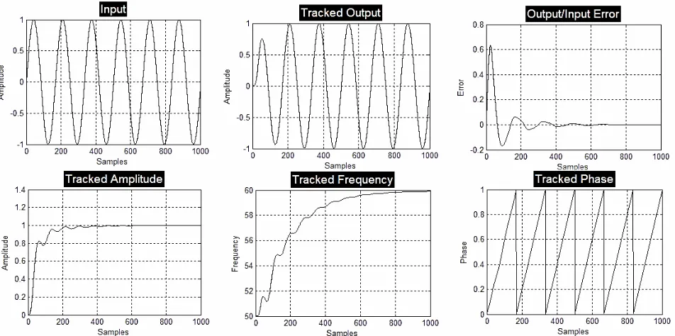
The fixed point model having the discrete integrator was simulated and its output, amplitude, phase and frequency results were verified. Figure 2 shows the results. Values for parameters 2µ1 = 500, 2µ2 = 8,000 and 2µ3=0.02 have been considered.
4. System Generator Based Implementation
After successful implementation of the Simulink based design for the sampling time of ‘1’ the system generator based design was implemented on equaling basis. Even when it comes to system generator based implementation for simple designs it is much trickier than implementa-tion of the Simulink designs. So a block by block imple-mentation and verification technique was implemented in order to avoid waste of time during debugging of poten-tial problems by eliminating most of their causes at the design step. A mixed (15_15, 15_13, 20_5, 15_6, 15_7 & 14_13) bit fixed point architecture was developed to effi-ciently allocate resources.
4.1. Block by Block Implementation, Verification
Each block of the Simulink based reference model was designed separately for the system generator based model by studying the block behavior for the outputs generated when the specific inputs were applied. The full system implementation can be performed separately by many designers at the same time while cutting short the product development time. This technique also helps to eliminate any design compatibility bugs at the implementation stage.
Figure 2. Simulation results for tracked amplitude (A[n]), frequency (w[n]) and phase (Φ[n]) along with the test input and tracked output.
Figure 3. Simulink block diagram for the discrete integrator.
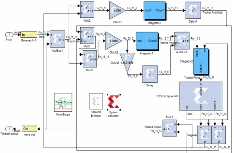
Figure 4. Top level module diagram for Xilinx system gen-erator.
the technique used. Verification is preformed to check the outputs match those desired by our system.
4.2. Calculating Sine and Cosine Function
DDS compiler 4.0 along with output buffer registers has been used in Sin_Cos_Lut mode to calculate sine and cosine for the tracked phase input as it is the most rele-vant block for generating the outputs we require for the set of inputs we have as our phase input range is -1<
Φ[n]< 1.
4.3. Parallel Path Balancing
A couple of parallel paths were identified having
differ-ent latency and were balanced using a delay elemdiffer-ent to match the outputs required by the system e.g. the custom discrete integrator being use has a unit delay and the par-allel path to the adder has only combinational delay so a unit delay was introduced in the parallel path to balance both paths and get the desired output for the block. All other blocks are readily available in the XSG environ-ment and were used directly with appropriate settings to implement the design.
5. Optimization
[image:3.595.60.285.437.526.2]Xilinx System Generator® Based Implementation of a Novel Method of Extraction of Nonstationary Sinusoids 10
Figure 5. Xilinx System Generator Based Implemented Architecture.
Figure 6. Flow chart for block by block implementation and verification.
pipelined optimized architecture for the algorithm [2] implemented using XSG. Figure 8 shows the histogram for path delay after its critical path was optimized.
6. Results
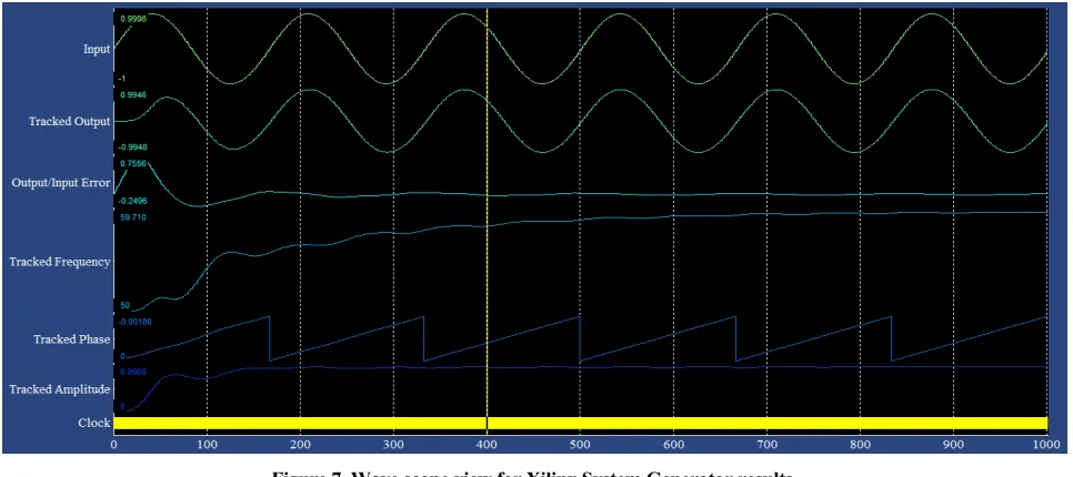
The optimized partially pipelined architecture was
[image:4.595.145.451.432.623.2]Figure 7. Wave scope view for Xilinx System Generator results.
Figure 8. Histogram for path delay.
Figure 9. Integrator2 with enable.
Figure 10. Power Analysis.
Xilinx System Generator® Based Implementation of a Novel Method of Extraction of Nonstationary Sinusoids 12
Figure 11. Simulation results for noisy input tracking performance.
Table 1. Design analysis.
Optimization Device
Spartan6-xc6slx16-csg324 Before After
Device Utilization Summary
Slice Logic Utilization: Number of Slice Registers:
Number of Slice LUTs: 1,160 109 116 358 Slice Logic Distribution:
Number of occupied Slices: Number of MUXCYs used: Number of LUT-FF pairs:
327 1,288 1,163 117 328 360 IO Utilization:
Number of bonded IOBs: 31 31
Specific Feature Utilization: Number of RAMB 16:
Number of RAMB 8: Number of BUFGs:
Number of DSP48A1s: 6 1 1 4 6 1 1 4
Maximum Operating Frequency
MHz 40.912 100.482
Throughput
Mbit/s 68.186 94.201
Throughput per slice
Mbit/s/slice 0.208 0.805
Power Utilization
Watts 0.098 0.071
opment of larger integrated architectures on available resources. Xilinx Spartan6-xc6slx16-csg324 was targeted as the design chip to serve as reference for the results published here. Figure 4 represents the test system for the developed XSG block. The tracking validation for the developed hardware based architecture was obtained by tracking a noisy input sinusoid. I76587 shows the
simu-lation results for the noisy input and tracked output gen-erated by the filter implemented. Sampled noisy input sinusoid is filtered to obtain the source signal.
7. Conclusions
The XSG based architecture for the novel adaptive filter was designed and implemented successfully showing promising results. This filter block can be integrated within large systems [11] fulfilling the design require-ments for different systems for their XSG based imple-mentation and ultimately their hardware based develop-ment for use in real-time user based applications [8], [9], [10]. The developed design can serve as a reference model for further improvement in this design or future XSG based development of similar models.
8. Acknowledgements
Engr. Jamal Ahmed and Engr. Saad bin Ayaz thanks for your help and support regarding reconfigurable design issues, adaptive filter theory and adaptive control.
REFERENCES
[1] A. K. Ziarani, “Extraction of Nonstationary Sinusoids,” Ph.D., Uni. Toronto, Toronto, Canada, 2002.
[2] A. K Ziarani and A. Konrad, “A Method of Extraction of Nonstationary Sinusoids,” Signal Processing, Vol. 84, No. 8, 2004, pp. 1323-1346.
doi:10.1016/j.sigpro.2004.05.008.
[3] A. K. Ziarani and Konrad, “An Adaptive Noise Reduction Technique,” Circuits and Systems, 2001. MWSCAS 2001. Proceedings of the 44th IEEE 2001 Midwest Symposium on, Vol. 1, 2001, pp. 251-254.
[image:6.595.58.289.325.642.2]http://www.xilinx.com/tools/sysgen.htm.
[5] M. Ownby, W. H. Mahmoud, “A Design Methodology for Implementing DSP with Xilinx® System Generator for Matlab®,” System Theory, 2003. Proceedings of the 35th Southeastern Symposium on , Vol., No. 16-18, 2003, pp. 404- 408.
[6] M. Bahoura, H. Ezzaidi, “FPGA-implementation of a Sequential Adaptive Noise Canceller Using Xilinx Sys-tem Generator,” Microelectronics (ICM), 2009 Interna-tional Conference on, No. 19-22, 2009, pp. 213-216. doi:10.1109/ICM.2009.5418650
[7] A. K. Ziarani, I. M. Blumenfeld, A. Konrad, “Experi-mental Verification of a Novel Method of Extraction of Nonstationary Sinusoids,” Circuits and Systems, 2002. MWSCAS-2002. The 2002 45th Midwest Symposium on , Vol. 1, No. 4-7, 2002, pp. I- 455-8.
[8] M. J. Fitzpatrick, D. M. McNamara and A. K. Ziarani, “Real-time Hearing Assessment Device Based on Distor-tion Product Otoacoustic Emissions,” Acoustics, Speech,
and Signal Processing, 2005. Proceedings. (ICASSP '05). IEEE International Conference on, Vol. 5, No. 18-23, 2005, pp. v/625-v/628.
doi:10.1109/ICASSP.2005.1416381
[9] A. K. Ziarani and A. Konrad, “A Nonlinear Adaptive Method of Elimination of Power Line Interference in ECG Signals,” BiomedIcal Engineering, Vol. 49, 2002, pp. 540-547.doi:10.1109/TBME.2002.1001968
[10] D. M. McNamara, A. Goli and A. K. Ziarani, “A Novel Approach for Doppler Blood Flow Measurement,” Engi-neering in Medicine and Biology Society, 2008. EMBS 2008. 30th Annual International Conference of the IEEE, Vol., No. 20-25, 2008, pp. 1883-1885.
doi:10.1109/IEMBS.2008.4649553
[11] M. L. Schenne, A. K. Ziarani and T. H. Ortmeyer, “A Novel Adaptive Flicker Measurement Technique,” Inter-national Journal of Electrical Power & Energy Sys-tems, Vol. 33, No. 10, 2011, pp. 1686-1694,
![Figure 1. Block diagram for the novel adaptive algorithm [2].](https://thumb-us.123doks.com/thumbv2/123dok_us/7880839.740311/2.595.64.281.85.220/figure-block-diagram-novel-adaptive-algorithm.webp)