International Journal of Emerging Technology and Advanced Engineering
Website: www.ijetae.com (ISSN 2250-2459, Volume 2, Issue 7, July 2012)35
Parallel Squarer Design Using Pre-Calculated Sum of Partial
Products
Manasa S.N
1, S.L.Pinjare
2, Chandra Mohan Umapthy
3 1Manasa S.N, Student of Dept of E&C &NMIT College2S.L Pinjare ,HOD of E&C &NMIT College
3Chandra Mohan Umapthy ,Assistant Professor &NMIT College
Abstract—Power is becoming a precious resource in modern VLSI design, even more than area. With large number of Applications requiring support of functional units like squares, cubes and other higher order units, it becomes imperative that such functions be implemented in hardware. This paper proposes a novel architecture for modular, scalable &reusable hybrid squaring circuit. Comparison is made between different implementationof squaring circuit. The implementation results show a significant improvement in performance in terms of area, power & timing
Keywords—Squarer,SquaringCircuit,Multiplier,Low Power etc.
I. INTRODUCTION
The advances in VLSI technology, more and more functionality complexity has been integrated into digital designs to better support target applications. With many applications requiring support for floating point arithmetic, complex arithmetic modules like multipliers and powering units are now being extensively used in design. With technology scaling, the goal has been to operate designs at the fastest possible frequency to achieve high performance. The problem with these complex arithmetic blocks like multipliers and squaring units is that they require longer cycle times for computation. In order to achieve the frequency requirements, these designs invariably end up being pipelined, which results in increases in area and thus incurs a power penalty for operating at higher clock speeds. In many applications a higher power penalty cannot be tolerated and designers have to budget the power associated with individual resources.
Multiplier designs require large area and consume a considerable amount of power per computation. For powering operations where a general-purpose multiplier is not necessary, this results in power being wasted. We propose to use dedicated powering units which perform a specific function in place of a multiplier which has been designed for general-purpose computation. The advantage with using dedicated Squaring units is that they consume less power compared to general-purpose multipliers. Squaring is a special case of multiplication.
By using dedicated resources one can save a considerable amount of power which allows designers to remain inside their power budgets.
Recently, lot of research has been conducted in order to develop different methodologies to implement squarer’s, giving more importance to improve delay & reducing area constraints. Due to which a new scheme was developed to compromise the above-mentioned trade-offs, which is called Hybrid Squarer’s. Greater emphasis is given on Hybrid Squarer’s, which Comprises of Memory Elements & Computing Logic.
The remainder of this paper is organized as follows. Section II presents a brief description of existing algorithms used in the designs of squaring units for unsigned/Signed followed by the designs multiplication of two binary numbers for unsigned/Signed. We present a way to use Quarter squaring units to perform multiplication of two binary numbers in section III. Section IV details the implementation and experimental results followed by a conclusion in section V.
II. BINARY MULTIPLICATION AND SQUARING
A. Binary Squarer’s
Squares are a special case of multiplication where both inputs are identical. Since the two inputs are identical, many optimizations can be made in the implementation of a dedicated squaring unit[3]. Such a squaring unit requires less area compared to multipliers as nearly half of the partial products can be combined using the equivalence Ai
Aj + Aj Ai = 2 Ai Aj which can be represented by adding Ai
Aj to the next column to the left. This reduces the depth,
which can be defined as the number of partial products to be added together in a column. With a reduction in depth, the design can operate faster as the number of terms on the critical path reduces. Fig.1 shows a 4-bit unsigned squaring unit. We can observe from Fig.1 that two A1A0 terms in
column 2 are reduced to having only one A1A0 term in
column 3. Similarly other partial products can be reduced. Also the property that A0 A0 = A0 allows reducing terms in
International Journal of Emerging Technology and Advanced Engineering
Website: www.ijetae.com (ISSN 2250-2459, Volume 2, Issue 7, July 2012)36 The square of a 4-bit number can be computed by adding the rows at the bottom part of Fig. 1. From Fig. 1 we observe that the depth has also reduced; an initial depth of four for a multiplier configuration was reduced to three for squaring[4]. Fig 3 shows the proposed architecture[8].
Fig1: Partial Product Reduction in Unsigned Squaring Operation
Fig3: Block diagram of the Proposed Architecture
Proposed Algorithm:
The algorithm consists of following steps:
The given input is partitioned into two parts, each part is treated as a separate unit processed individually by further units.
· Find the square of each part.
· Find twice the product of individual part.
· Add the above results suitably to get the final result.
If X is a five-digit number, who’s square has to be computed.
X = abcde.
Find square of abc = (abc) 2. Find square of de = (de) 2.
Find twice the product of abc & de = 2(abc)(de) Find the sum of the above results to get the square of X. Ex:
1. Let X = 12345. a = 123, b = 45. Find square of abc = (123) 2 = 15129. Find square of de = (45) 2 = 2025.
Find twice the product of abc & de = 2 * (123) * (45) = 11070.
Find the sum of the above results to get the square of X = 152399025.
The above theory can be extended for any given number X. Hence, by mathematical inspection; the proposed algorithm is proven for any arbitrary number X
B. Binary Multiplication Using Mux
The techniques for performing binary multiplication involve three basic steps: namely, – Generation of Partial Products, Reduction of Partial Products and Addition of the final two rows of partial products. An M×N bit multiplication can be viewed as forming N partial product arrays, each of M bits and adding them together according to their weights. Multiplication is performed either by using a Shift – Add algorithm or by using Parallel multiplication techniques. The Shift – Add method requires M-cycles to perform M×N-bit Multiplication
In this method we are using 2-Mux to generate partial product, the select line of Mux are controlled by counter. The output of Mux is given to a Multiplier, the result of Multiplier is stored in Register & controlled By clock.When clock Enables the Register we perform the Shift-Add method requires M-cycles to perform M×N-bit Multiplication All the recoding bit arrays are then added together according to their weights to obtain the final product.
The architecture of Multiplier designed using Mux shown below:
Fig4:Multiplier designed using mux.
C. Digital Multiplier:
A basic LUT-based multiplier is simply a lookup table with the addresses arranged so that part of the address is the multiplicand and the other part is the multiplier. The data width should be set to the sum of the address width to accommodate the product.
Implementing a Basic/Digital Multiplier:
International Journal of Emerging Technology and Advanced Engineering
Website: www.ijetae.com (ISSN 2250-2459, Volume 2, Issue 7, July 2012)37 The memory will store the appropriate product values. To multiply the upper four bits by the lower four bits, feed both values into the address and clock the memory. The appropriate product value will appear on the RAM output. A diagram of this LUT-based multiplier implementation is shown in Figure 1 on page 2. Since the memory block is synchronous, this configuration will result in a synchronous multiplier, whose clock frequency is only limited by the data access time of the memory. While this approach is more efficient than implementing multipliers in gates, it can consume a large amount of memory. The amount of memory required increases with the square of the bit width. Theexample above demonstrates a 4 x 4 bit multiplier with 256 eight-bit words of storage required. For an 8 x 8 bit multiplier, 65,536 16-bit words must be stored using this technique.
Characteristics of Basic Multiplier:
A. Iterative shift add routine
B. N clock cycles to complete C. Very compact design
D. Serial input can be MSB or LSB first depending on direction of shift in accumulator
E. Parallel output
Partial Product Multipliers
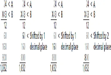
One way to mitigate the amount of memory required is to use partial product multiplication. This technique combines the lookup table approach with elements of longhand multiplication. For example, to multiply 24 x 43 = 1,032 using longhand, simplify the problem into the sum of four multiply functions and three add functions (Figure 2).
[image:3.612.79.257.533.653.2](4 × 3 + ((2 × 3) × 10)) + (((4 × 4) + ((2 × 4) × 10)) × 10) = 1,032
Fig 5.Partial Product Multiplier technique
Implementing a Partial Product Multiplier
In logic this same technique can be used to reduce the amount of memory required to perform a multiply function.
Using a basic lookup table technique, an eight-bit by eight-bit multiply would require 128 kb of storage. As shown in Figure 3 on page 3, using partial product multipliers, the same procedure can be accomplished using 1 kb of storage. In order to accomplish this in logic, using A as the multiplicand and B as the multiplier, take the lower four bits of A and multiply it by the lower four bits of B using the lookup table technique. Then take the upper four bits of A and multiply it by the lower four bits of B and shift the partial product result to the left by four. Then add the two results together for the first part of the product. For the second part of the product, multiply the lower four bits of A by the upper four bits of B. Then do the same with the upper four bits of both A and B and shift this partial product value to the left by four. Add the two values of the previous calculation and shift the whole result to the left by four. Then add the first part of the product to the second part of the product for the final result. While this technique is not as fast as implementing the entire multiply as a single memory element, it does greatly reduce the amount of memory required at the expense of using more core tiles.
III. QUARTER SQUARE TECHNIQUE
The squaring units requiring less area and power as compared to multipliers, it is interestingto assess the use of squaring units to perform multiplication. There are various Methods to obtain a multiplication of two numbers using squares instead of using multipliers. One of the most widely used methods in algebra is the quarter square method [5]. In mathematical terms, the quarter square algorithm can be expressed as.
A x B=1⁄ 4{(A+B)2 - (A-B)2}
[image:3.612.379.509.604.693.2]In this method, to obtain the product of two numbers, we obtain their sum and difference. The obtained sum and difference are squared, and the difference of these two squares when divided by 4 provides the result. As in binary arithmetic, divide by 4 operation can be easily accomplished by shifting right two digits. The quarter square technique is illustrated in Fig.5.
Fig 6. Quarter Square Technique
International Journal of Emerging Technology and Advanced Engineering
Website: www.ijetae.com (ISSN 2250-2459, Volume 2, Issue 7, July 2012)38 From Fig.6 we observe that if we have two 8-bit unsigned numbers, the sum can result in a carry, similarly with two 8-bit signed numbers, the difference can generate an overflow. In order to produce a correct result we need a (8+1) bit adder for computation of sum and difference, and hence one would need at least (n+1) bit squaring units to correctly perform an n-bit squaring operation.
IV. EXPERIMENTS AND RESULTS
An 8/16/32/64-bit multiplier performing signed/ unsigned operations based on multiplier using Mux Algorithm has been described in Verilog. As multipliers support signed operations, we use squaring units designed for signed operations for all the results and comparisons.
We implemented the Quarter square algorithm using the Squaring unit designs to perform signed/unsigned multiplication. We designed 8/16/32/64/bit squaring units to support 8-, 16-, 32-,64 bit multiplication, respectively. The performance of all squaring circuits are evaluated on the same device Spartan xc3s400 & Vertex XC2vp30 with a speed grade of 4 & 7.The results suggest that the proposed architecture is faster than Multiplier.
TABLE I
Area Requirement Using Spartan3
Bits Squarer Multiplier usingMux
Quarter Multiplier
Digital Multiplier
4 4 13 7 4
8 6 19 11 10
16 8 35 17 40
[image:4.612.319.559.156.266.2]
Fig 7. Area Requirements of various designs.
TABLE II
Delay (ns) Requirement using Spartan3
Bits squarer Multiplier usingMux
Quarte Multiplie r
Digital Multiplier
4 13.48 19.6 18.93 13.68
8 16.44 21.12 19.91 18.13
16 16.66 21.89 21.25 22.32
Delay=Input delay + Output delay
From tables I & II, we can conclude that the proposed scheme is more efficient in terms of area, timing & power. The above results can be further improved by using the Look Up Table (LUT) approach to calculate the
intermediate squaring values.
TABLE III
Area Requirement using spartan3
Bits With lut Without lut
2 2 3
4 4 6
6 7 10
[image:4.612.324.564.347.635.2]8 20 26
[image:4.612.42.296.415.644.2]International Journal of Emerging Technology and Advanced Engineering
Website: www.ijetae.com (ISSN 2250-2459, Volume 2, Issue 7, July 2012)39
TABLE IV
Delay (ns) Requirement using Spartan3
[image:5.612.60.277.152.405.2]Fig 9. Delay Requirements of various designs.
TABLE V
Area Requirement using Vertex2p
Fig 10. Area Requirements of various designs.
TABLE VI
Delay (ns) Requirement using Vertex2p
Number of Bits
Squarer Multiplier Using Mux
Digital Multiplier
Quarter Multiplier
4 7 10.39 7.6 10.2
8 8.95 11.8 10.09 11.09
16 9.29 12.24 12.47 12.89
32 11.32 13.10 15.5 17.92
64 16.52 20.92 19.61 24.13
Delay = Input delay+ output delay.
[image:5.612.322.571.313.689.2]Simulation Result:
Fig 11. 8-bit Squaring Circuit
Fig 12. 16-bit Squaring Circuit.
Fig 13. 64-bit Squaring Circuit
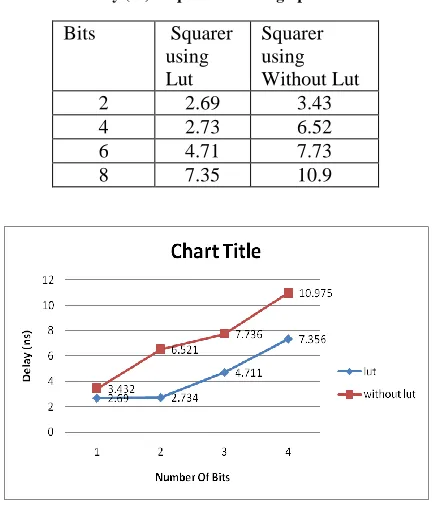
Bits Squarer
using Lut
Squarer using Without Lut
2 2.69 3.43
4 2.73 6.52
6 4.71 7.73
8 7.35 10.9
Bits Squarer Multiplier Using Mux
Quarter Multiplier
Digital Multiplier
4 3 14 7 3
8 5 19 9 10
16 8 35 11 40
32 13 67 85 157
[image:5.612.44.282.454.689.2]International Journal of Emerging Technology and Advanced Engineering
Website: www.ijetae.com (ISSN 2250-2459, Volume 2, Issue 7, July 2012)40 We compare four designs based on their area or the maximum number ofpartial productsin acolumn. Table I shows the area requirements for the types multiplier and the squaring units. As seen from Table II, the maximum delay requirement for the Multiplier & the other Multiplier unit is more than that of the Squarer. From the table we can prove that area reduces means power automatically reduces.
Fig. 7&10 plots the area requirements for various designsUnder the same constraints. From the results we can observe that the squaring units require only about 55% of the multiplier area. Designing multipliers with quarter Squarer techniques results in an area penalty of about 20-60% over Digital multiplier. From the area requirements of quarter square multiplier and squaring units, we find that the area overhead of adders in the multiplier design is about 20-30% of the area of the squaring unit.
The Delay required for each design is shown in Table II we observe that the squaring units consume about 50% of the Delay consumed by the Digital multiplier to perform squaring. However, when a multiplier is built using the quarter square technique, it consumes more power than the Digital Multiplier as the design requires the use of two squaring units and three adders for every multiplication. The adder overhead significantly affects the overall power. The Table III & IV shows area & delay requirement using without Lut for Multiplier & with Lut for Squarer architecture. With Lut consume less Area & Delay compared to Without Lut. The Table V & VI shows the area & delay requirement using Vertex.
Fig 11,12,13 shows the simulation result of 8,16,64 bit Squarer. Result remains the same for all other types of multiplier.
V. CONCLUSION
The paper presents a case for the use of dedicated squaring units in applications where squares are required in large numbers, which otherwise would be implemented using general purpose multipliers. A method of using squaring units to perform multiplications is presented, and the tradeoffs as compared to conventional multipliers are presented.
We provide results for area and power requirements in unsigned/Signed squaring units and quarter square multiplier for 8/16/32-bits. The low area and power required per computation provide significant advantages when dedicated squaring units are used in a design instead of a general purpose multiplier. The Salient Feature are Modular & Scalable architecture, Easy & simple to implement, Low Power consumption, Less Area & Better Timing can be achieved.
REFERENCES
[1 ] Risojevic, V.; Avramovic, A.; Babic, Z.; Bulic, P,‖ A simple pipelined squaring circuit for DSP ―,IEEE 29th International Conference Computer Design (ICCD),2011, Page(s): 162 – 167. [2 ] Kuan Jen Lin; Yu Chan Chiu; Tzu-Hao Lin‖ A decimal squarer with
efficient partial product generation‖, 18th IEEE/IFIP VLSI System on Chip Conference, 2010 , Page(s): 213 – 218
[3 ] Garofalo. V. Coppola. M. De Caro. Napoli. E. Petra, N.. Strollo, A.G.M.‖ A novel truncated squarer with linear compensation function‖, IEEE International Symposium on Circuits and Systems (ISCAS), Proceedings, 2010 , Page(s): 4157 – 4160
[4 ] Oberman, Stuart F. and Flynn, Michael J. "Division Algorithms and Implementations." IEEE Transcation on Computers (1997): pp833-854, 2010
[5 ] Datla, S.R, Thornton, M.A, Mutual, D.W. , "A Low Power High Performance Radix-4 Approximate Squaring Circuit," Application specific Systems, Architectures and Processors,. 20th IEEE International Conference on , vol., no., pp.91-97, 7-9 July2009 [6 ] Taek-Jun Kwon, Jeff Sondeen, Jeffrey Draper, ―Floating-Point
Division and Square Root using a Taylor-Series Expansion Algorithm‖, 50th IEEE International Midwest Symposium on Circuits and Systems, August 2007, pp. 305 – 308
[7 ] Cho, K.-J.; Chung, J.-G.‖A parallel squarer design using
pre-calculated sum of partial product ―Electronics letter ,2007,vol 43 pp1414-1416
[8 ] Hong, Sun-Ah.Kim, Yong-Eun, Chung. Jin-Gyun. Lee, Sung-Chul, ―Efficient Squarer Design Using Group Partial Products ―IEEE Workshop on Signal Processing Systems,2007 , Page(s): 146 – 150 [9 ] Cho, K.-J, Chung.J.-G.‖ Low error fixed-width two's complement
squarer design using Booth-folding technique‖ Computers & Digital Techniques, IET , 2007 , Page(s): 414 – 422.
[10 ]Shuli Gao, Chabini. N, Al-Khalili. D, Langlois. P‖ Efficient Realization of Large Integer Multipliers and Squarers‖ IEEE North-East Workshop on Circuits and Systems. 2006 , Page(s): 237 - 240 [11 ]Chandra Mohan Umapathy ―High speed squarer‖ 20th IEEE/IFIP