Direction Finding for Bistatic MIMO Radar
with Non-Circular Sources
Hao Chen1, 2, *, Xinggan Zhang2, Yechao Bai2, and Jinji Ma1
Abstract—A new direction finding method for multiple-input multiple-output (MIMO) radar with non-circular sources is proposed. This method takes advantage of the properties of non-circular sources to formulate a new virtual array. Then based on the ESPRIT like algorithm, the bearing of targets is estimated. In addition, the direction of departure (DOD) and direction of arrival (DOA) are paired automatically. Compared with the uniform circular array estimation of signal parameters by rotational invariance techniques (UCA-ESPRIT), the proposed method can achieve better estimation performance and deal with more targets. We also provide the Cramer-Rao Lower Bound (CRLB) for comparison. Simulation results demonstrate the effectiveness and feasibility of the proposed method.
1. INTRODUCTION
Multiple-input multiple-output (MIMO) radar exploits multiple antennas to transmit diversity waveforms and makes use of multiple antennas to receive the signal reflected from targets simultaneously, which has attracted a lot of attention [1–4]. MIMO radar can obtain waveform diversity, spatial diversity, polarization diversity and large degrees of freedom (DOF), thereby has demonstrated the potential to dramatically improve target parameter estimation, target identification and anti-jamming performance [5–7]. It is well known that direction finding and localization of target are two basic functions for radar system. Among the most popular high resolution methods for direction of departure (DOD) and direction of arrival (DOA) estimation, subspace algorithms such as multiple signal classification (MUSIC) [8] and estimation of signal parameters by rotational invariance techniques (ESPRIT) [9] are widely used.
For direction finding of MIMO radar with uniform linear array (ULA), many methods have been proposed [10–14]. Reduced-dimension MUSIC for angle estimation has been derived in [10], which only requires one-dimensional search and can save computational time. Unfortunately, the algorithm will fail to work in the presence of array gain-phase error. It is proved in [11] that the ESPRIT algorithm exploits invariance properties of both transmit and receive ULAs, and can estimate the transmit and receive angles of MIMO radar efficiently. However, the algorithm estimates the two angles separately in each dimension and requires an additional pairing procedure. The ESPRIT method without pairing is proposed in [12], and by doing so, the transmit and receive angles can be paired automatically. Uniform circular array (UCA) can provide both azimuth and elevation angles, which are attractive in many practical applications [15–17]. Based on the MIMO radar with transmit UCA, the three-dimensional (3-D) coordinates of targets are estimated [18].
Most current works on direction finding with MIMO radar do not consider non-circularity characteristics of the sources. Non-circular signals, such as binary phase shift keying (BPSK) and amplitude shift keying (ASK), are widely used in practical scenarios. By exploiting non-circularity
Received 9 January 2018, Accepted 18 March 2018, Scheduled 2 April 2018 * Corresponding author: Hao Chen ([email protected]).
is proposed for direction finding with a bistatic MIMO radar, which can deal with more targets and pair automatically [22]. Based on the Euler’s formula, real-valued ESPRIT (RV-ESPRIT) for non-circular sources is presented [23]. Combining the ESPRIT and ROOT-MUSIC techniques, a joint DOA and DOD estimate method is proposed in [24]. To reduce computational complexity, a low-complexity ESPRIT-ROOT-MUSIC algorithm is presented in [25]. For coexistence of circular and non-circular signals, the ESPRIT and Unitary ESPRIT (U-ESPRIT) [26], and joint digitalization based [27] algorithms are proposed. The above ESPRIT like methods need to perform eigenvalue decomposition (EVD), which are time consuming. To avoid the EVD, propagator method (PM) is applied to direction finding with non-circular sources [28]. Nevertheless, when the array of MIMO radar is the UCA, the above direction finding methods will be disabled. To the best of our knowledge, direction finding for MIMO radar with UCA and non-circular signals has not yet been published.
In this paper, we address the problem of associating direction finding from a scheme of MIMO radar, where the transmit array is a UCA, and the receive array is a ULA. Firstly, we define two selection matrices. By applying the rotational invariance characteristics of receive ULA, the DOA can be firstly estimated. The steering vectors which contain the transmit elevation angle and the azimuth are coupled in the transmit UCA; therefore, the key step for estimating the DOD is to decouple the two angles from the received data. The UCA-ESPRIT algorithm for non-circular signals is derived to estimate the transmit elevation angles and azimuth angles of MIMO radar. The proposed method can be paired automatically. Furthermore, the Cramer-Rao Lower Bound (CRLB) on the estimation of the targets with non-circular sources is also derived.
The remainder of this paper is organized as follows. The data model for strictly non-circular sources of MIMO radar is introduced in Section 2. In Section 3, a novel joint multiple parameter estimation method for MIMO radar system is proposed. In Section 4, we deduce the CRLB of estimation. Simulation results and performance analysis are shown in Section 5. Finally, Section 6 concludes the paper.
Notations: The superscripts (·)T, (·)H, (·)∗, and (·)−1 denote transpose, conjugate transpose, complex conjugate, and matrix inversion, respectively. The Hadamard product of two matrices A and Bis represented byAB, and the Kronecker product is symbolized byA⊗B. If and 0f denote thef ×f identity matrix and matrices of zeros. In addition, Re{·}extract the real part of a complex matrix, and the matrixΠF denotes theF×F exchange matrix with ones on its anti-diagonal and zeros elsewhere.
2. SIGNAL MODEL OF MIMO RADAR
Considering a MIMO radar system consisting of a UCA for transmit array and a ULA for receive array. The transmit UCA hasM elements which are distributed over the circumference of a circle with radius
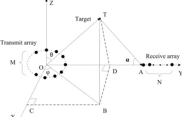
r. The receive ULA has N elements with the space d between adjacent antennas. Assuming that the transmit array transmitsM narrowband non-circular sources, reflected by K noncoherent targets, and then received by the N receiving arrays at the Y-axis as shown in Fig. 1. The length between the center of UCA and the reference point of ULA is La. The kth target is located at (αk, θk, ϕk), where
αk denotes the DOA,θk the transmit elevation angle, andϕk the transmit azimuth. The output of the receiver can be written as
x(t) =
K
i=1
ρi(t)ar(αi)aTt(θi, ϕi)bi(t) +z(t) (1)
where ρk(t) is the reflection coefficient of the kth target, and ar(αk) and at(θk, ϕk) are the receive steering vector and transmit steering vector, respectively. bi(t) is the transmitting non-circular signal. z(t) is the additive Gaussian white noise with mean zero and variance σ2. Note that the noises are
independent of each other. The receive and transmit steering vector can be represented as
ar(α) =
1, ej2πλdcosα, . . . , ej2π d
λ(N−1) cosα
Figure 1. Geometry of MIMO radar.
at(θ, ϕ) =
ej2πrsinθcos(ϕ−γ0)/λ, ej2πrsinθcos(ϕ−γ1)/λ, . . . , ej2πrsinθcos(ϕ−γM−1)/λ
(3)
whereλis the wavelength of transmitting signal, and γm = 2πmM ,m= 0,1, . . . , M −1.
After matched filters, the received data can be expressed as
X=AS+Z (4)
where X ∈ CMN×L is the received data sampling, with L being the number of snapshots. A = [A1,A2, . . . ,AK]∈CMN×K is the steering vectors of the radar system, withAK =ar(αK)⊗at(θK, ϕK).
S = [s1(t),s2(t), . . . ,sK(t)]T ∈ CK×L is the signal matrix, with sK(t) = ρKbK and the noise Z∈CMN×L. Due to the non-circularity of sources, the signal matrix Scan be represented as [20]
S=ΨS0 (5)
where Ψ= diag([ejβ1, ejβ2, . . . , ejβK]) is a diagonal matrix whose diagonal elements are the stationary complex phase shifts, andS0 is a real valued symbol matrix.
3. PROPOSED PARAMETER ESTIMATION METHOD
In this section, we formulate a new virtual array based on the received data and present a direction finding method in which the DOAs and DODs can be paired automatically.
3.1. Estimation of the DOA
In order to utilize the non-circularity of the sources, we define an extended measurement matrix as
X(nc)=
X ΠMNX∗
=
AS ΠMNA∗S∗
+
Z ΠMNZ∗
(6)
It is known that S0 in Equation (5) is a real valued symbol matrix, and we have S0 =S0∗ = Ψ−1S.
Equation (6) can be rewritten as
X(nc) =
AS ΠMNA∗Ψ∗S∗0
+
Z ΠMNZ∗
=
A ΠMNA∗Ψ∗Ψ−1
S+
Z ΠMNZ∗
RX =E X(nc)XH(nc) =ESΣSEHS +ENΣNEHN (8)
where ΣS and ΣN are diagonal matrices whose diagonal elements contain the largest K eigenvalues and smallest 2M N −K eigenvalues. The signal subspace matrix ES is composed of K eigenvectors corresponding to K eigenvalues of RX, and EN is the noise subspace matrix including the rest of eigenvectors.
Define two selection matrices as
J1= [IN−1,0(N−1)×(N+1)]⊗IM (9)
J2= [0(N−1)×1,IN−1,0(N−1)×N]⊗IM. (10)
Here J1 select the first (N −1)M columns of the matrix, and the index is from 1 to (N −1)M. J2
select the second (N−1)M columns of the matrix, andthe index is from M+ 1 to N M. Let E1 and
E2 be submatrices formed fromES as
E1=J1ES (11)
E2=J2ES (12)
Assume that the diagonal elements of Λr = diag[η1, η2, . . . , ηK] are the eigenvalues of Φr =T−1ΛrT,
which satisfy E2 =E1Φr. ThenΦr can be obtained by the least squares method, and the DOA of the kth target can be obtained by
αk = arccos
λarg(ηk)
2πd
, k= 1,2, . . . , K. (13)
3.2. Estimation of the DOD
In this part, we firstly extract the matrices which contain steering vector of the transmitting array from the received data. Then based on the UCA-ESPRIT algorithm for non-circular sources, the elevation angle and azimuth of target can be estimated.
Similar toJ1 and J2, we also define another two selection matrices as
J3 = [IN−1,0(N−1)×1]⊗IM (14)
J4= [0(N−1)×1,IN−1]⊗IM. (15)
Then the rotated factor can be expressed as
X1=J3X=J3AS+J3Z (16)
X2 =J4X=J4AS+J4Z. (17)
The autocorrelation and crosscorrelation matrixes ofX1andX2areR1 =E[X1X1H],R2 =E[X2X1H],
owing to J4A = J3AQ, where the diagonal elements of Q are the steering vector of receiver array.
According to [18], define the matrix RS as
RS =R2 R1−σ2IMN−1 −1
. (18)
Via eigenvalue decomposition ofRS, we can then obtain the eigenvectorE(SK)that spans the beamspace signal subspaces, whereE(SK)=J3A.
Define a selection matrix J5 as
J5 = [ar( ˆα1),ar( ˆα2), . . . ,ar( ˆαK)]H ⊗IM (19)
where αk is the estimation of DOA in Equation (13). Finally, the matrix which contains the steering
vector of the transmitting array can be obtained by
Yt= 1
N −1J5E
(K)
Based on the phase mode excitation method, the non-circular (NC) UCA-ESPRIT algorithm can be used to estimate the transmit elevation angle and azimuth of non-circular sources. The beamformer FHe is defined as [15]
FHe =CBVH (21)
where CB = diag(j−P, . . . , j−1, j0, j−1, . . . , j−P), P = 2πr/λ. Assumingr=λ, we have the maximum mode order P = 6. V = √1
M [v−P, . . . ,v0, . . . ,vP] and vp =
1, ej2πp/M, . . . , ej2πp(M−1)/MH,
p= 1,2, . . . , P. Thus, the beamspace data matrix can be written asY =FeHYt=AeS+Ze. The number of available beams is doubled by forming
Y(nc)=
Y IMY∗
=
AeS IMA∗eS∗
+
Ze IMZ∗e
(22)
whereM = 2P + 1. Similar to Equation (7), we have
Y(nc)=
Ae IMA∗eA−e1
S+
Ze IMZ∗e
=A(nc)S+Z(nc)
(23)
Define the unitary matrix
QH2M = √1
2
IM ΠM jIM −jΠM
, (24)
and the matrix
B(nc) =QH2MY(nc). (25)
Assume that the K dominant left singular vector of B(nc) is Sr(nc) which spanning the column space of QH2MA(nc); therefore, the matrix Q2MSr(nc) spans the space ofA(nc). LetC0(nc)=I2⊗C0, where
C0= diag
(−1)P, . . . ,(−1)1,1,1, . . . ,1
∈CM×1
. The signal subspace matrix can be expressed as
S(0nc)=C(0nc)Q2MS(rnc). (26)
We define Δ(−1) = [IM,0M×2],Δ(0) = [0M×1,IM,0M×1], and Δ(1) = [0M×2,IM], where M = 2P −1. The selection matrices Δ(−1),Δ(0) and Δ(1) choose the first, middle and last M
elements. Let
W(i) =I2⊗Δ(i) (27)
Γ(nc)=I2⊗Γ (28)
S(nci)=W(i)S(0nc) (29) where Γ =λ/(πr)diag{1−P, . . . ,−1,0,1, . . . , P −1}, and i=−1,0,1. Therefore, the submatrices of the signal subspace matrixS(0nc) satisfy
E(nc)Ψ¯ =Γ(nc)S(0)nc (30)
where E(nc) =
S(nc−1),S(1)nc
, and Ψ¯ =
Ψ Ψ∗
. Equation (30) is overdetermined when M > K, and
has a unique solution Ψ¯ by utilizing the least squares method. Considering that the eigenvalues of Ψ¯ areγk,k= 1,2, . . . , K, then the transmitting elevation angles θk and azimuth φk can be obtained by
θk=arcsin(|γk|) (31)
φk= arg(γk). (32)
From Equations (19), (20), and (21), we note that the beamspace matrix Y in Equation (22) for estimating the DODs is formed by the estimated DOAs. There is no mismatch in the eigenvaluesηkand
Here we derive the CRLB for MIMO radar with non-circular sources. CRLB is the low bound for parameter estimation error, which is usually used to measure the performance of the estimation algorithm. It is known that the inverse of the Fisher information matrix (FIM) is the CRLB [29], which bounds the error variance of the estimation from the radar system. Under the signal and system model in this paper, the FIM can be expressed as
FM = 2L
σ2
Re
DHΠ⊥AD
RTS
(33)
where σ2 is the variance of the additive Gaussian white noise, and L is the number of snapshots. D = [Dα,Dθ,Dϕ], with Dk(α) = ∂ar(αk)
∂α ⊗at, Dk(θ) = ar ⊗ ∂a∂θt(θk), and Dk(ϕ) = ar ⊗ ∂at∂ϕ(ϕk).
Moreover, Π⊥A=I−A AHA−1AH,RTS =SSHL. Define the FIM for the target as
F(α, θ, ϕ) =
Fαα Fαθ Fαϕ Fθα Fθθ Fθϕ Fϕα Fϕθ Fϕϕ
(34)
where
Fυω = 2L
σ2
Re
(Dk(υ))HΠ⊥A(Dk(ω))
RTS
(35)
and υ, ω∈[α, θ, ϕ].
Therefore, the CRLB can be obtained by
B(α, θ, ϕ) =F(α, θ, ϕ)−1. (36)
5. RESULTS AND DISCUSSION
In this section, we provide three simulations to illustrate the performance of the proposed method. For all the simulations, the transmit array is a UCA of radiusr=λ, and the number of transmit elements is chosen as M = 21. Meanwhile, the receive array is a ULA with d=λ/2, and the number of receive elements is chosen to be N = 21. The length between the center of UCA and the reference point of ULA is La= 80 km. The radar system transits the BPSK signals which are noncoherent.
The root mean square error (RMSE) is defined to evaluate the performance of estimation, which is expressed as
RMSE = K k=1 C i=1
( ˆχki−χk)2 (37)
whereK is the number of targets, C= 500 the number of Monte Carlo simulations, ˆχki the estimated
result of thekth target, and the χk the real parameter of the kth target. To analyze the performance
of the proposed algorithm, we have compared the simulation results with that of the UCA-ESPRIT algorithm in [15] and Li’s method in [18]. In addition, the CRLB of the estimated parameters with non-circular source is also included for comparison.
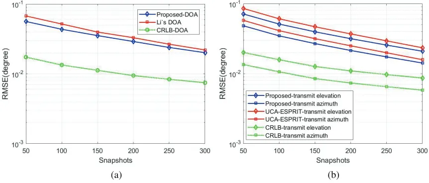
In the first test, we study the performance for parameter estimation against the SNR. The SNR is varied from 0 dB to 20 dB, and the number of snapshots is 120. There are two noncoherent sources from directions (15◦,44◦,63◦) and (20◦,60◦,80◦). In Fig. 2, we depict the RMSE of the DOA and DOD of target 1, respectively. The estimate results of target 2 are achieved in Fig. 3. To further evaluate the estimation performance, the CRLB is also plotted for comparison. From the results, we see that the RMSE decreases with improvement of SNR in the above algorithms, and it is obvious that the performance of our method is better than Li’s method and UCA-ESPRIT algorithm.
(b) (a)
Figure 2. (a) DOA and (b) DOD estimation performance of target 1.
(b) (a)
Figure 3. (a) DOA and (b) DOD estimation performance of target 2.
(b) (a)
10o 20o
30o 40o
50o 60o 40o
50o
60 80
90o
100o
Elevation angle
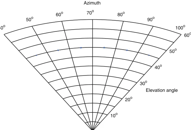
Figure 5. Transmit elevation angle and azimuth for six sources.
Figure 4 shows the simulation result of target 1. It is indicated that the parameter estimate performance is improved with the increase of snapshots.
In the final test, we study the maximum of the estimated sources. As a fact, the UCA-ESPRIT for circular signal can only deal with the sources that are less than K = 5 in the case of r=λ. However, the theoretical analysis shows that the recognizable sources of the proposed method are twice as many as that of the UCA-ESPRIT. Herein, we consider the six non-circular sources case for comparison. In this case, the DOA and transmit elevation angles of the six sources are the same at (35◦,45◦). The azimuths are 45◦,55◦,65◦,75◦,85◦, and 95◦, respectively, and the SNR is fixed at 25 dB. From the first and second simulations, we obtain that the estimation DOA of target has a high precision. Therefore, we only show estimation results of the transmit angles and azimuth angles in Fig. 5. Obviously, it is shown that the proposed method can deal with more sources than the UCA-ESPRIT.
6. CONCLUSION
In this paper, we present a direction finding method for MIMO radar with non-circular sources. In this method, the characteristics of non-circular sources are utilized; therefore, the estimate performance is better than Li’s method and the UCA-ESPRIT. Moreover, because the number of available sensors is virtually doubled, the proposed method can deal with more sources than the UCA-ESPRIT. Results of simulation demonstrate the effectiveness of the proposed method.
ACKNOWLEDGMENT
This work was supported by the National Natural Science Foundation of China under Grant No. 41671352, Basic Research Program of Jiangsu Province under Grant No. BK20151391, and Natural Science Research Project of Universities in Anhui Province under Grant No. KJ2017A329.
REFERENCES
1. Fishler, E., A. Haimovich, R. Blum, D. Chizhik, L. Cimini, and R. Valenzuela, “MIMO radar: An idea whose time has come,” Proc. IEEE Radar Conference, 71–78, Apr. 2004.
3. Li, J. and P. Stoica, “MIMO radar diversity means superiority,” Proc. the 14th Adaptive Sensor Array Process Workshop, 1–64, Dec. 2006.
4. Haimovich, A. M., R. S. Blum, and L. J. Cimini, “MIMO radar with widely separated antennas,”
IEEE Signal Process. Magazine, Vol. 25, 116–129, 2008.
5. Lehmann, N. H., E. Fishler, A. M. Haimovich, R. S. Blum, L. J. Cimini, and R. A. Valenzuela, “Evaluation of transmit diversity in MIMO-radar direction finding,”IEEE Trans. Signal Process., Vol. 55, 2215–2225, 2007.
6. Xu, L. Z., J. Li, and P. Stoica, “Target detection and parameter estimation for MIMO radar systems,”IEEE Trans. Aerosp. Electron. Syst., Vol. 44, 927–939, 2008.
7. Chan, F. K. W., H. C. So, L. Huang, and L. T. Huang, “Parameter estimation and identifiability in bistatic multiple-input multiple-output radar,” IEEE Trans. Aerosp. Electron. Syst., Vol. 51, 2047–2056, 2015.
8. Schmidt, R. O., “Multiple emitter location and signal parameter estimation,” IEEE Trans. Antennas Propag., Vol. 34, 276–280, 1986.
9. Roy, R. and T. Kailath, “ESPRIT-estimation of signal parameters via rotational invariance techniques,” IEEE Trans. Acoust. Speech, Signal Process., Vol. 37, 984-995, 1989.
10. Zhang, X. F., L. Y. Xu, L. Xu, and D. Z. Xu, “Direction of departure (DOD) and direction of arrival (DOA) estimation in MIMO radar with reduced-dimension MUSIC,”IEEE Commun. Lett., Vol. 14, 1161–1163, 2010.
11. Chen, D. F., B. X. Chen, and G. D. Qin, “Angle estimation using ESPRIT in MIMO radar,”
Electron. Lett., Vol. 44, 770–770, 2008.
12. Chen, J., G. Hong, and S. Weimin, “Angle estimation using ESPRIT without pairing in MIMO radar,”Electron. Lett., Vol. 44, 1422–1423, 2008.
13. Dang, X. F., B. X. Chen, M. L. Yang, and G. M. Zheng, “Beamspace unitary ESPRIT algorithm for angle estimation in bistatic MIMO radar,” International J. Antennas Propag., Vol. 2015, 1–9, 2015.
14. Oh, D., Y. C. Li, J. Khodjaev, J. W. Chong, and J. H. Lee, “Joint estimation of direction of departure and direction of arrival for multiple-input multiple-output radar based on improved joint ESPRIT method,” IET Radar Sonar Navig., Vol. 9, 308–317, 2015.
15. Mathews, C. P. and M. D. Zoltowski, “Eigenstructure techniques for 2-D angle estimation with uniform circular array,” IEEE Trans. Signal Process., Vol. 42, 2395–2407, 1994.
16. Mathews, C. P., “Enhancing UCA-ESPRIT for non-circular sources,” Proc. International Symposium Signal Process. Applica., 1–4, Feb. 2007.
17. Jackson, B. R., S. Rajan, B. J. Liao, and S. C. Wang, “Direction of arrival estimation using directive antennas in uniform circular arrays,”IEEE Trans. Antennas Propag., Vol. 63, 736–747, 2015. 18. Li, J., H. Li, L. B. Long, G. S. Liao, and H. Griffiths, “Multiple target three-dimensional coordinate
estimation for bistatic MIMO radar with uniform linear receive array,” EURASIP J. Adv. Signal Process., Vol. 2013, 1–11, 2013.
19. Liu, Z. M., Z. T. Huang, Y. Y. Zhou, and J. Liu, “Direction-of-arrival estimation of noncircular signals via sparse representation,” IEEE Trans. Aerosp. Electron. Syst., Vol. 48, 2690–2698, 2012. 20. Steinwandt, J., F. Roemer, M. Haardt, and G. D. Galdo, “Performance analysis of multi-dimensional ESPRIT-type algorithms for arbitrary and strictly non-circular sources with spatial smoothing,”IEEE Trans. Signal Process., Vol. 65, 2262–2276, 2017.
21. Cai, J. J., W. Liu, R. Zong, and B. Wu, “Sparse array extension for non-circular signals with subspace and compressive sensing based DOA estimation methods,” Signal Process., Vol. 145, 59– 67, 2018.
22. Yang, M. L., B. X. Chen, and X. Y. Yang, “Conjugate ESPRIT algorithm for bistatic MIMO radar,”Electron. Lett., Vol. 46, 1692–1693, 2010.
51–54, 2011.
25. Wang, X. P., W. Wang, and D. J. Xu, “Low-complexity ESPRIT-Root-MUSIC algorithm for non-circular source in bistatic MIMO radar,”Circuits Syst. Signal Process., Vol. 34, 1265–1278, 2015. 26. Zheng, G. M., J. Tang, and X. Yang, “ESPRIT and unitary ESPRIT algorithms for coexistence of
circular and noncircular signals in bistatic MIMO radar,”IEEE Access, Vol. 4, 7232–7240, 2016. 27. Chen, H., C. P. Hou, W. P. Zhu, W. Liu, Y. Y. Dong, and Z. J. Peng, “ESPRIT-like two-dimensional
direction finding for mixed circular and strictly noncircular sources based on joint diagonalization,”
Signal Process., Vol. 141, 48–56, 2017.
28. Wang, W., X. P. Wang, and X. Li, “Propagator method for angle estimation of non-circular sources in bistatic MIMO radar,” Proc. IEEE Radar Conference, 1–5, Apr. 2013.