International Journal of Emerging Technology and Advanced Engineering
Website: www.ijetae.com (ISSN 2250-2459, Volume 2, Issue 6, June 2012)446
Optimised FFT design using Constant Co-efficient Multiplier
Chandan.M
1, S.L.Pinjare
2, Chandra Mohan Umapthy
31
Chandan M, Student of Dept of E&C &NMIT College
2
S.L Pinjare, HOD of E&C &NMIT College
3
Chandra Mohan Umapthy, Assistant Professor &NMIT College
Abstract—Power is becoming a precious resource in modern VLSI design, even more so than area. This paper proposes a novel architecture for modular, scalable &reusable hybrid constant co-efficient multiplier (KCM) circuit. Comparison is made between of kcm and multiplier. The implementation results show a significant improvement in performance in terms of area, power & timing. In This paper, we propose to design an 8-point FFT using kcm instead of complex multiplier and multiplier. Here our goal is to implement Radix-2 8-point FFT in hardware using hardware language (verilog) here time constraint is measured with the help of Xilinx FPGA (Field Programmable Gate Array).
Keywords—DFT, FFT, Butterfly, Radix, KCM, Multiplier, Low Power.
I. INTRODUCTION
With advances in VLSI technology, more and more functionality complexity has been integrated into digital designs to better support target applications. With many applications requiring support for floating point arithmetic, complex arithmetic modules like multipliers and powering units are now being extensively used in design. With technology scaling, the goal has been to operate designs at the fastest possible frequency to achieve high performance. The problem with these complex arithmetic blocks like multipliers and squaring units is that they require longer cycle times for computation. In order to achieve the frequency requirements, these designs invariably end up being pipelined, which results in increases in area and thus incurs a power penalty for operating at higher clock speeds. In many applications a higher power penalty cannot be Tolerated and designers have to budget the power associated with individual resources.
Multiplier designs require large area and consume a considerable amount of power per computation. For powering operations where a general-purpose multiplier is not necessary, this results in power being wasted. We propose to use dedicated powering units which perform a specific function in place of a multiplier which has been designed for general-purpose computation. The advantage with using dedicated KCM is that they consume less power compared to general-purpose multipliers.
KCM is a special case of multiplication. By using dedicated resources one can save a considerable amount of power which allows designers to remain inside their power budgets.
Recently, lot of research has been conducted in order to develop different methodologies to implement kcm giving more importance to improve delay & reducing area constraints. Due to which a new scheme was developed to compromise the above-mentioned trade-offs, which is called Optimized KCM using look up table[12]. Greater emphasis is given on Optimized KCM, which Comprises of Memory Elements & Computing Logic.
The remainder of this paper is organized as follows. Section II presents a brief description of existing algorithms used in the multiplication of two numbers followed by the designs of KCM units for unsigned numbers. We present a way to use kcm units to perform multiplication of two numbers in FFT in section III. Section IV details the implementation and experimental results followed by a conclusion in section V.
II. KCMALGORITHM AND MULTIPLIER
Multipliers can be optimised to have a single input are called Constant Coefficient Multipliers (KCM’s).Small blocks of ROM, store 16 partial products relating to the fixed coefficient and then use a simple adder to combine these products. As a result, KCM’s are less than one third of the size of full multipliers[13].
Multiplying by a constant appears often in application such as
1) Gain-offset Amplification 2) Color-space conversion 3) Digital Filtering
A. Kcm algorithm
This section describes on Constant Co-efficient Multiplier with optimized look-up table [12]. Special emphasis is given on Modularity, Scalability & Reusability aspects of the design.
International Journal of Emerging Technology and Advanced Engineering
Website: www.ijetae.com (ISSN 2250-2459, Volume 2, Issue 5, May 2012)447 Table I: Optimised Look-up table (LUT)
LUT 0 47 94 141 188 235
In the above table contains a six LUT location has a constant value i.e 47 multiplied by multiplicand varies from 0 to 5. The product of each multiplication stored in corresponding LUT. By using LUT values. We can find any n-bit number value ie any number multiplied by 47.the operation can be performed by fetching values from LUT and finally performing shifting and add operation.
The variable input as a 2-digit decimal value, using T to represent the tens column and U for its units, product can be calculated by math transform formula then multiplier’s output becomes Product = (T x 47) x 10 + U x 47
Ex:
Let X=16 T=1 U=6
Product = (T x 47) x 10 + U x 47 = (1 x 47) x 10 + (5+1) x 47 = ( 47) x 10 + (235+47) x 47
=13724
The above theory can be extended for any given number X by mathematical inspection[12].
Fig1: Block diagram of the proposed kcm Architecture
B. Multiplier
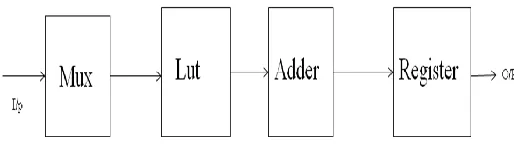
The techniques for performing binary multiplication involve three basic steps: namely, – Generation of Partial Products, Reduction of Partial Products and Addition of the final two rows of partial products. An M×N bit multiplication can be viewed as forming N partial product arrays, each of M bits and adding them together according to their weights.
Multiplication is performed either by using a Shift – Add algorithm or by using Parallel multiplication techniques. The Shift – Add method requires M-cycles to perform M×N-bit Multiplication
In this method we are using 2-Mux to generate partial product, the select line of Mux are controlled by counter. The output of Mux is given to a Multiplier, the result of Multiplier is stored in Register & controlled By clock .When clock Enables the Register we perform the Shift-Add method requires M-cycles to perform M×N-bit Multiplication All the recoding bit arrays are then added together according to their weights to obtain the final product.
III. EFFICIENT DESIGN AND IMPLEMENTATION OF FFT
A. Introduction
The Fourier transform is the method of changing time representation to frequency representation. The discrete Fourier transform (DFT) is a one of the Fourier transform, used in Fourier analysis. It transforms one function that is time into another that is frequency, so as to get discrete signals, hence called the DFT, of the original function. The DFT of a given sequence x[n] can be computed using the formula [4]
X
(
k
)
W
KnNN n
n
x
1 0)
(
0
k
N
1
---- (1)
W
e
jN N
2
Where, WN is twiddle factor. Twiddle factors referred to as the root- of- unity complex multiplicative constants in the butterfly operations of the FFT algorithm, used to recursively combine smaller discrete Fourier transforms. Practically, at the input there is time domain so only real values should be present but for our convenience we apply input data sequence x(n) having both real and imaginary term We observe that for each value of k, direct computation of X(k) involves N complex multiplications (4N real multiplications) and N-1 complex additions (4N-2 real additions). Consequently, to compute all N values of the DFT requires N 2 complex multiplications and N 2 -N
[image:2.612.48.305.510.583.2]International Journal of Emerging Technology and Advanced Engineering
Website: www.ijetae.com (ISSN 2250-2459, Volume 2, Issue 5, May 2012)448 There are many distinct FFT algorithms involving a wide range of Mathematics, from simple complex-number arithmetic to group theory and number theory [4].
The Fast Fourier Transform is an optimized computational algorithm to implement the Discrete Fourier Transform to an array of 2^N samples where, N is the length of samples. It allows determining the frequency of a discrete signal, representing the signal in the frequency domain, convolution, etc. This algorithm has a complexity of (N*log2 (N)).The ordering minimizes the number of fetches or computations of the twiddle-factor values. Since the bit reverse or computations of the twiddle-factor values. Since the bit reverse of a bit-reversed index is the original index, bit-reversal can be performed fairly simply by swapping pairs of data.
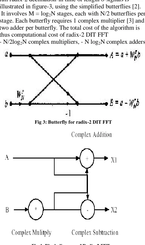
"DFT" refers to a mathematical transformation or function, regardless of how it is computed, whereas "FFT" refers to a specific family of algorithms for computing DFT’s. Fig 2 shows radix-2 decimation in time FFT algorithm for length 8-signal.This is built up of three stages whose first stage can be discussed further [4].
B. Radix-2 DIT FFT Algorithm for Length 8 Signals
[image:3.612.325.560.165.563.2]With the introduction of field programmable gate arrays (FPGAs), it is feasible to provide hardware for application specific computation design. The changes in designs in FPGA’s can be accomplished within a few hours, and thus result in significant savings in cost and design cycle. FPGAs offer speed comparable to dedicated and fixed hardware systems for parallel algorithm.
Fig 2: Radix-2 decimation in time FFT algorithm for length 8-signals
The radix-2 decimation in time is applied recursively to the two lengths N/2 DFT’s to save computation time. The full radix-2 decimation-in time of length 8-signals is illustrated in figure-3, using the simplified butterflies [2]. It involves M = log2N stages, each with N/2 butterflies per stage. Each butterfly requires 1 complex multiplier [3] and two adder per butterfly. The total cost of the algorithm is thus computational cost of radix-2 DIT FFT
- N/2log2N complex multipliers, - N log2N complex adders
Fig 3: Butterfly for radix-2 DIT FFT
Fig 4: Block diagram of Radix-2 FFT
Fig 3, shows butterfly diagram for radix-2 DIT FFT[4], whose block-diagram is as shown in fig-4. This is the first stage of FFT algorithm which is specified in fig 3. As we have seen earlier, there is the presence of complex number in twiddle factor so we need to use complex operation. Here again three blocks are used that is complex addition, complex subtraction, complex multiplication. The complex multiplier can also be designed using adder, subtractor, shifter and LUT .
[image:3.612.65.283.509.694.2]International Journal of Emerging Technology and Advanced Engineering
Website: www.ijetae.com (ISSN 2250-2459, Volume 2, Issue 5, May 2012)449 For the first step, the partial products are generated. For the second step, the partial products are reduced to one row of final sums and carries. For the third step, the final sums and carries are added to generate the result. Here the complex number multiplication can be divided into two main components known as real part and imaginary part as in [3]. This complex multiplier is shown by the following equation,
(a + j b)(c + j d ) = (ac – bd ) + j( bc + ad ) ---(2)
In this paper, where c and d are twiddle factor, having constant co-efficient number. By creating LUT’s for both c and d. LUT contains a six location with constant values called c-LUT i.e variable c value multiplied with numbers varies from 0 to 5 and product stored in corresponding location. Same procedure for d-LUT also i.e variable d value multiplied with numbers varies from 0 to 5 and product stored in corresponding location. And performing kcm algorithm .the inputs to the c-LUT and d-LUT are variables a and b. the operation can be performed by fetching values from c-LUT and d-LUT and finally performing shift and add operation.
By implementing this technique, multiplier block is reduced so area and power will be reduced. Complex multiplier finds extensive applications in areas like digital signal processing, communication etc. It is one of basic building block of digital system. The adder and subtractor are all built using full and half adders. Half adders find the sum of two binary numbers and provide a sum and a carry.
IV. EXPERIMENTS AND RESULTS
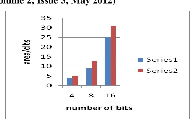
[image:4.612.346.539.124.252.2]An 8/16/32/64-bit performance of KCM and digital Multiplier are evaluated on the device Spartan xc3s400 with a speed grade of 4.The results suggest that the proposed architecture is faster than Multiplier
TABLE I. Area Requirement Using Spartan3
Bits kcm Digital Multiplier
4 4 5
8 9 13
16 25 31
[image:4.612.362.528.292.358.2]
Fig 5. Area Requirements of KCM and multiplier designs. TABLE II. Delay (ns) Requirement using Spartan3
Bits KCM Digital
Multiplier
4 10.937 11.48
8 11.438 14.815
16 12.48 16.326
[image:4.612.376.514.420.501.2]From tables I & II, we can conclude that the proposed scheme is more efficient in terms of area, timing & power.
TABLE III . Area Requirement using Vertex
Bits kcm Digital Multiplier
4 4 5
8 7 11
16 10 17
[image:4.612.361.527.541.618.2]32 17 28
TABLE IV. Delay (ns) Requirement using Virtex
Bits KCM Digital
Multiplier
4 5.59 6.283
8 5.701 8.262
16 6.710 9.830
32 7.198 13.752
[image:4.612.101.237.608.674.2]International Journal of Emerging Technology and Advanced Engineering
Website: www.ijetae.com (ISSN 2250-2459, Volume 2, Issue 5, May 2012)450
Simulation Result:
Fig- 6. 16-bit KCM Circuit.
Fig-7 input to FFT
We compare kcm and Multiplier for performing multiplication. Table III shows the area requirements for the multiplier and the multiplier. As seen from Table IV, the maximum delay requirement for the Multiplier & than kcm. From the table we can prove that area reduces means power automatically reduces.
Fig-8 output of FFT .
V. CONCLUSION
The paper presents a case for the use of dedicated optimised KCM units in applications where multiplier are required in large numbers, which otherwise would be implemented using general purpose multipliers. A method of using KCM units to perform multiplications is presented, and the tradeoffs as compared to conventional multipliers are presented. We provide results for area and power The low area and power required per computation provide significant advantages when dedicated KCM units are used in a design instead of a general purpose multiplier in FFT design. The Salient Feature are Modular & Scalable architecture, Easy & simple to implement, Low Power consumption, Less Area & Better Timing can be achieved.
REFRENCES
[1] Saad Bouguezel, M. Omair Ahmad, “IMPROVED RADIX-4 AND
RADIX-8 FFT ALGORITHMS”IEEE. Department of Electrical and
Computer Engineering Concordia University 1455 de Maisonneuve Blvd. West Montreal, P.Q., Canada.
[2] Ali Saidi ,” DECIMATION-IN-TIME-FREQUENCY FFT
ALGORITHM” Motorola Applied Research, Paging and Wireless Data
International Journal of Emerging Technology and Advanced Engineering
Website: www.ijetae.com (ISSN 2250-2459, Volume 2, Issue 5, May 2012)451
[3] Rizalafande Che Ismail and Razaidi Hussin ”High Performance
ComplexNumber Multiplier Using Booth-Wallace Algorithm” School of
Microelectronic Engineering Kolej University Kejuruteraan Utara Malaysia.
[4] J.G.Proakis and D.G.Manolakis, ”Digital Signal Processing,
Principles,algorithms and applications” Prentice Hall India Publication.
[5] J.A.Hidalgo ,V.Moreno- Vergara,O.Oballe, “A Radix-8 Multiplier
Unit Design For Specfic Purpose”,Dept of the Electronica ,
E.T.S.I.Industriales
[6] C. S. Burrus and T. W. Parks,” DFT/FFT and Convolution
Algorithms”, New York ,NY : John Wiley,1985.
[7] A. Saidi “Generalized FFT algorithm”, Proc. ICC,pp.227-231,May 1993.
[8] Robert Polge and Brooks Lawence, “Comparion of New Multiple Radix Fast fourier Number Theoetic Transform with FFT Algorithm in
Terms of Performance and Hardware Cost”, ECC Department, University
of
Alabama Huntsville, AL35899,IEEE : 744-749.
[9] Keiichi Satoh and Jubee Taba, “Complex Multiplier Suited for FPGA
Structure”, in Proc. ITC-CSCC, 2008, P.341-344.
[10] Xilinx Co.”Xcell journel vol 58-59”,2007 spring.
[11] Y.N .Chang and K.K Parhi,”An efficient pipelined FFT architecture,”
IEEE Trans. Circuits Systems II, vol. 50, pp.322-352, June 2003.
[12] Constant-coefficient multipliers save FPGA space, time expert column Steve Knapp
[13] Knapp, S, “FPGA lookup tables build flexible pattern matchers,”
PE&IN, May 1998, pgs 56-60.
[14] Chapman K, “Constant Coefficient Multipliers for the XC4000E,”
ApplicationNote XAPP 054, Dec 11, 1996,
Xilinx Inc