DISTRIBUTION SYSTEM RELIABILITY IMPROVEMENT USING DISTRIBUTED GENERATORS.
SITI HAIRANI BINTI JAMAL
A thesis submitted in
fulfillment of the requirement for the award of the Degree of Master of Electrical Engineering
Faculty of Electrical and Electronic Engineering Universiti Tun Hussein Onn Malaysia
v
ABSTRACT
vi
ABSTRAK
vii
CONTENTS
TITLE i
DECLARATION ii
DEDICATION iii
ACKNOWLEDGEMENT iv
ABSTRACT v
ABSTRAK vi
CONTENT vii
LIST OF TABLES ix
LIST OF FIGURES x
LIST OF SYMBOL AND ABBREVIATION xiii
LIST OF APPENDICES xiv
CHAPTER 1 INTRODUCTION 1
1.1 Project Background 1 1.2 Problem Statements 6
1.3 Project Objectives 8
viii
CHAPTER 2 LITERATURE REVIEW 10
2.1 Introduction 10
2.2 Theories 10
CHAPTER 3 METHODOLOGY 27
3.1 Project Methodology 27
CHAPTER 4 RESULTS AND DISCUSSION 38
4.1 Introduction 38
4.2 Results and Discussion 39
CHAPTER 5 CONCLUSION RECOMMENDATION 54
5.1 Conclusion 54
5.2 Recommendation 55
REFERENCES 56
APPENDICES 59
ix
LIST OF TABLES
2.1 Strengths and weaknesses of reciprocating engines 12 2.2 Strengths and weakness of microturbines 13 2.3 Strengths and weakness of combustion turbines 14 2.4 Strengths and weakness of Photovoltaic 16 2.5 Strengths and weakness of fuel cell type 17 2.6 Strengths and weakness of Wind Turbines 18 2.7 The strengths and weaknesses of Hybrid system 20 3.1 Type and number of customer for Six (6) Villages 28
3.2 Key Specification of PV Panel 32
3.3 Key Specification of Battery Model 35 4.1 SAIDI tabulated for placing Distributed Generator at existing 48
location
x
LIST OF FIGURES
1.1 Rural Electrification : Tanjung Labian Lahad Datu, Sabah
3
1.2 Distributed Generator connected at Stesen Solar Hibrid Tanjung Labian, Lahad Datu Sabah
4
1.3 Single Line diagram of Tanjung Laian Lahad Datu 5 1.4 Sabah Map: Location of Tanjung Labian Lahad Datu,
Sabah
7
2.1 Rural Electrification : Tanjung Labian Lahad Datu, Sabah
11
2.2 Reciprocating engines 12
2.3 Microturbine 13
2.4 Industrial Combustion turbine 14
2.5 Photovoltaic cell, module and array 15
2.6 Solar panel farm 16
2.7 Fuel Cells 17
2.8 Wind turbines 18
2.9 Example of Hybrid system for distributed generator connected to distribution line
19
xi
2.11 (a) Radial Structure (b) Loop Structure (c) Meshed Structure
21
2.12 Sample of Distribution system with Radial Structure 22 3.1 Methodology approach using flow chart 27
3.2 Solar radiation typical data 29
3.3 Annually Solar irradiation 30
3.4 Hybrid System 30
3.5 Symbol of solar cell in SimElectronics 31 3.6 Equivalent circuit of the solar cell 31 3.7 Standalone Photovoltaic as a Distributed Generator 32
3.8 Showing battery block 33
3.9 Showing a thevenin equivalent battery model 34 3.10 Battery as a Distributed Generator 34 3.11 Complete Diagram of Fuel Engine as Distributed
Generator
35
4.1 Tanjung Labian Distribution Network Diagram 39 4.2 Weekdays versus weekend load characteristic 40 4.3 The output waveform of Photovoltaic system 41 4.4 The three phase output voltage inverter after filtering
of all phases
41
4.5 The output waveform of Battery system 42
4.6 The output waveform of Voltage 42
4.7 The output waveform for current 43
xii
4.9 Irradiation (Solar Usage) 44
4.10 Battery Storage usage 45
xiii
LIST OF SYMBOLS AND ABBREVIATIONS
UTHM - Universiti Tun Hussein Onn Malaysia
kW - KiloWatt
km - Kilometer
PV - Photovoltaic
xiv
LIST OF APPENDICES
APPENDIX TITLE PAGE
CHAPTER 1
INTRODUCTION
1.1Project Background
Distributed generation is a new approach in electrical industry [1] and has been gradually increasing in the last few years and will rise even more in near future [2].
Due to high power demand, Utility such as Sabah Electricity Sdn Bhd (SESB), Tenaga Nasional Berhad (TNB) and Sarawak Energy Berhad (SEB) are continuously planning the expansion of the electrical networks. One of the methods used for the expansion of electrical networks is connecting distributed generator in the distribution system [3].
Distributed Generators is defined as a small-scale generation unit connected at or near the customer load. The technologies for Distributed Generators are based on reciprocating engines, photovoltaic, fuel cells, combustion gas turbines, micro turbines and wind turbines. This technology is also known as alternative energy system [4].
By connecting distributed generators in the distribution system, the power demand of the system can be satisfied and also improves the reliability of the electrical network [3].
2
In US, Distributed Generator uses as a sustainable and competitive form of generation, not just restricted to renewable energy. In light of the recent blackout in New York, it is proposed as a significant part of the solution to improve both security and reliability of supply, with islanded operation of distributed generation on microgrids a real prospect for the future. However, in Europe, it is viewed more renewable generation, which is given priority dispatch and should be accommodated where possible [6].
Most independent Distributed Generator such as photovoltaic (PV) as a generator, weak in stability and sustain the power supply since the source are mostly dependent on weather condition. Thus, a hybrid Distributed Generator is a solution. It is more practical and stable since it is based on more than one energy source. Besides, this hybrid system is suitable to use in remote areas with no access to utility grid.
Figure 1.1
For this station, a hybrid Distributed Generator system development using solar photovoltaic (PV) combined with fuel generator and
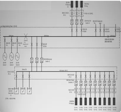
used to serve the village. Reliability of the system can be examined by using development software called MATLAB/SIMULINK program where this program will show the reliability impact of Distributed Generator. Figure 1.2 show connection of the Distributed Generator install at Station Solar Hybrid Tanjung Labian. The single line diagram of distribution system
Figure 1.1: Rural Electrification : Tanjung Labian Lahad Datu, Sabah For this station, a hybrid Distributed Generator system development using solar photovoltaic (PV) combined with fuel generator and battery storage systems used to serve the village. Reliability of the system can be examined by using development software called MATLAB/SIMULINK program where this program will show the reliability impact of Distributed Generator. Figure 1.2 show
nection of the Distributed Generator install at Station Solar Hybrid Tanjung Labian. The single line diagram of distribution system is shown in Figure 1.3.
3
: Rural Electrification : Tanjung Labian Lahad Datu, Sabah For this station, a hybrid Distributed Generator system development using
battery storage systems used to serve the village. Reliability of the system can be examined by using development software called MATLAB/SIMULINK program where this program will show the reliability impact of Distributed Generator. Figure 1.2 shows the nection of the Distributed Generator install at Station Solar Hybrid Tanjung
4
5
6
1.2Problem Statements
Nowadays, the electric power industry is facing huge changes with respect to structure, function, and regulation [3]. The use of distributed generators within distribution network has drawn attention due to several advantages that small scale generation can potentially provide to power utilities. The distributed generation has created a new way for the electric power generation. [3].
The electric power generation that is integrated within the distribution system is called distribution generation [3]. It is a new approach in electrical industry [1]. In order to achieve both reliability cost and worth requirement to the company, a study has been done to select a best possible location for distributed generators.
Thus, a lot of things need to be considered for installing distributed in distribution system such as impact on power flow, voltages, and reliability indices, which could be positive or negative [3]. Therefore, maintaining a reliable power supply is a very important issue for power system design and operation. At planning stage they faced by difficult problem of deciding how far they are justified in increasing the investment on their facilities to improve service reliability [6].
Figure 1.4: Sabah Map
Time constrain versus high demand bring the system are not
planned and dispatch since this is direct negotiation project between Contractor and Government Malaysia.
is taken as a case study. Estimates of the Statio
resource and actual system data are employed to assess the impact of Distributed Generated connection.
.
Figure 1.4: Sabah Map: Location of Tanjung Labian Lahad Datu, Sabah
Time constrain versus high demand bring the system are not
planned and dispatch since this is direct negotiation project between Contractor and Government Malaysia. Distributed Generation install in Tanjung Labian Lahad D
se study. Estimates of the Station Tanjung Labian
resource and actual system data are employed to assess the impact of Distributed Generated connection.
7
: Location of Tanjung Labian Lahad Datu, Sabah
8
1.3Project Objectives
General aim of this project is to evaluate power system reliability improvement using Distributed Generators installed in Station Solar Hybird Tanjung Labian, Lahad Datu, Sabah
The objectives of this project are:
1. To measure the characteristic such as Generator mode, Photovoltaic mode and battery mode during normal and super peak condition of Distributed Generator.
2. To investigate reliability on Station Solar Hybrid, Tanjung Labian by analyze the performance of existing Station Solar Hybrid, Tanjung Labian.
3. To perform reliability assessment on a distribution system circuit based on different location of Distributed Generator.
9
1.4Project Scope
The Scopes of this project are:
1. The study will be conducted at Station Solar Hybrid Tanjung Labian Lahad Datu, Sabah.
2. The Capacity Electric Power Installed at Station Solar Hybrid Tanjung Labian Lahad Datu to be investigate
(i) Engines Diesel installed Two (2) unit 500KVA One (1) unit 350kVA (ii) Fuel Cell or Battery installed Capacity 4320kWh
(iii) Inverter System installed 900kW Bi-Directional Inverter 750kW ‘Inverter & Control System’ (iv) Photovoltaic Panel installed Capacity 1.2MW
3. Village Coverage and Station Solar Hybrid Tanjung Labian Lahad Datu Sabah as a Measurement.
No Village Name No of Houses Load Demand
(kW)
1 Kg. Tg. Labian 175 197
2 Kg. Tg. Batu 125 140
3&4 Kg. Tanagian dan Kg. Bahagia 122 137
5 Kg. Sg. Bilis 101 114
6&7 Kg.Lok Sembuang dan Lok Buani 158 178
CHAPTER 2
LITERATURE REVIEW
2.1Introduction
In this chapter, the operation or method of the Distribution system using Distributed generator will be revealed so that this project could be understood easily.
2.2Theories
11
Rural Electrification:
Tanjung Labian , Lahad Datu Sabah
Distributed Generator:
√ Batery √ Photovoltaics
√ Reciprocating engines
Operational Factor:
√ Power Quality √ Reliability
Software:
[image:22.595.156.497.74.262.2]√ MATLAB/SIMULINK
Figure 2.1: Rural Electrification : Tanjung Labian Lahad Datu, Sabah
2.2.1 Distributed Generations
Distributed generation (DG) is currently being used by some customers to provide some or all of their electricity needs. There are many different potential applications for Distributed Generators technologies. For example, some customers use Distributed Generators to reduce demand charges imposed by their electric utility, while others use it to provide primary power or reduce environmental emissions. Distributed Generators can also be used by electric utilities to enhance their distribution systems. Several energy sources drive distributed generators including:
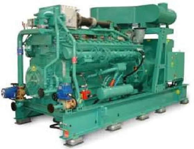
2.2.1.1 Reciprocating engines
12
[image:23.595.189.499.204.442.2]power, peaking power, and in cogeneration applications [7]. Figure 2.2 showing the example of Reciprocating engines. The strengths and weaknesses of reciprocating engines have been listed in Table 2.1[14].
Figure 2.2: Reciprocating engines
[image:23.595.130.516.559.749.2]13
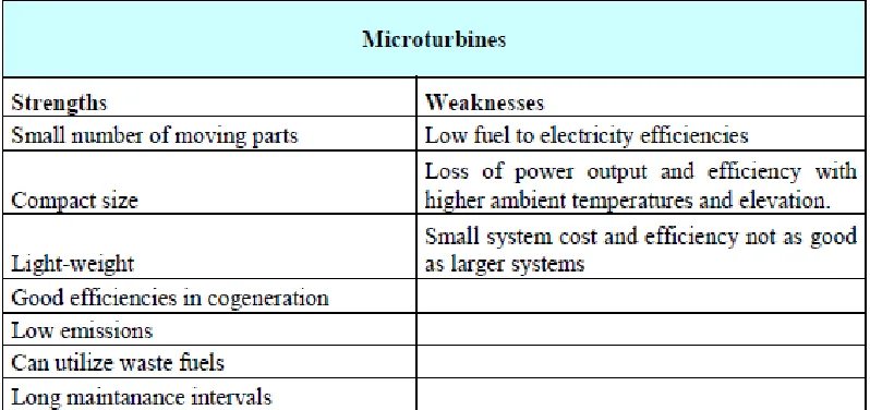
2.2.1.2Microturbines
[image:24.595.123.522.572.760.2]A new and emerging technology, microturbines are currently only available from a few manufacturers. Other manufacturers are looking to enter this emerging market, with models ranging from 30 to 200 kW. Microturbines promise low emission levels, but the units are currently relatively expensive. Obtaining reasonable costs and demonstrating reliability will be major hurdles for manufacturers. Microturbines are just entering the marketplace, and most installations are for the purpose of testing the technology [7]. Figure 2.3 presenting a Microturbine. The strengths and weaknesses of Microturbines have been listed in Table 2.2 [14].
Figure 2.3: Microturbine
14
2.2.1.3Industrial combustion turbines
[image:25.595.205.457.282.399.2]A mature technology, combustion turbines range from 1 MW to over 5 MW. They have low capital cost, low emission levels, but also usually low electric efficiency ratings. Development efforts are focused on increasing efficiency levels for this widely available technology. Industrial combustion turbines are being used primarily for peaking power and in cogeneration applications [7]. Figure 2.4 showing an Industrial combustion turbine. The strengths and weaknesses of Industrial Combustion Turbines have been listed in Table 2.3[14].
Figure 2.4: Industrial Combustion turbine
[image:25.595.123.518.482.730.2]15
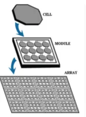
2.2.1.4 Photovoltaic
Commonly known as solar panels, photovoltaic (PV) panels are widely available for both commercial and domestic use [7]. PV power system converts sunlight into electricity [8]. Materials that are used for photovoltaic are mono-crystalline silicon, polycrystalline silicon, microcrystalline sili-con, cadmium telluride and copper indium selenide [9] [10].
[image:26.595.293.380.575.693.2]The basic unit of a photovoltaic power system is the PV cell, where cells may be grouped to form panels or modules. The panels then can be grouped to form large photovoltaic array that connected in series or parallel, as shown in Figure 2.5[8] [11]. Panels range from less than 5 kW and units connected in parallel increase the current and connected in series provide a greater output voltage to form a system of any size. The output characteristics of PV module depends on the solar irradiance, the cell temperature and output volt-age of PV module [9] [12].They produce no emissions, and require minimal maintenance. However, they can be quite costly. Less expensive components and advancements in the manufacturing process are required to eliminate the economic barriers now impeding wide-spread use of PV systems. Photovoltaic are currently being used primarily in remote locations without grid connections and also to generate green power [7]. Figure 2.6 shows a sample of Solar panel farm. The strengths and weaknesses of Photovoltaic have been listed in Table 2.4 [14].
16
Figure 2.6: Solar panel farm
Table 2.4 : Strengths and weakness of Photovoltaic
2.2.1.5 Fuel Cells
[image:27.595.117.521.374.522.2]17
Figure 2.7: Fuel cells
Table 2.5: Strengths and weakness of fuel cell type
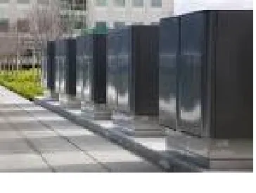
2.2.1.6Wind turbine systems
[image:28.595.124.527.274.522.2]18
[image:29.595.229.446.139.315.2]companies to provide green power [7]. Figure 2.8 below showing wind turbines. The strengths and weaknesses of Wind Turbine System have been listed in Table 2.6 [14].
Figure 2.8: Wind Turbines
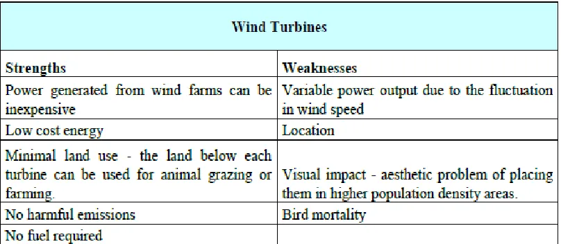
Table 2.6: Strengths and weakness of Wind Turbines
2.2.1.7Hybrid Systems
[image:29.595.120.524.391.567.2]19
[image:30.595.174.465.207.502.2]This Hybrid system is developed to improve on the performance of an individual Distributed Generators [7]. Photovoltaic combine with Reciprocating engines and battery to provide backup supply. This is to ensure a perfect balance exist between power demand and generated power [8]. Figure 2.9 shows example of Hybrid system for distributed generator connected to distribution line [14].
Figure 2.9: example of Hybrid system for distributed generator connected to distribution line.
The advantages of using Distributed Generator based hybrid systems are it increased the reliability of the hybrid system because it is based on more than one electricity generation source. Moreover, the hybrid system is suitable to use in remote areas or isolated locality with no access to utility grid [8] [15] [16].
20
[image:31.595.128.521.177.560.2]system [8]. The strengths and weaknesses of hybrid system have been listed in Table 2.7 and a sample of micro grid application in Figure 2.10 [14].
[image:31.595.193.453.358.545.2]Table 2.7: The strengths and weaknesses of Hybrid system
Figure 2.10: A sample of micro grid application
21
Generator installation location. With depend on this factors, the Distributed Generator installed can be either positive or negative to the system [17].
For example, when the Distributed Generator is attached downstream, it can confuse the voltage regulator by setting a voltage lower than the required value. Thus, proper coordinate installing Distributed Generator can improve the voltage profile of the system and also improve the power system stability. Beside, placing the Distributed Generator at optimal location can reduce the losses on the feeder [17].
2.2.2 Electric Power System Structure
Distribution system’ design depending on customer load, cost of installation and operational and maintenance operation. Generally there are three electric power structure can be illustrious. There are Radial, Loop and meshed structure. Figure 2.11 below showing (a) Radial Structure (b) Loop structure (c) Meshed Structure [18].
[image:32.595.142.512.467.614.2](a) (b) (c)
Figure 2.11 (a) Radial structure (b) Loop structure (c) Meshed Structure
22
[image:33.595.167.473.321.459.2]structure can be improved by using loop structure. Whereby all substation or customers are connected via double circuit or line. During a disturbance, the faulted section can be isolated and the loop is split-up into two parts. The faulted section can be energizing back once the faulted section recover. For this case, the repair time is considered the time needed for fault localization and necessary switching actions. For meshed structure, all substation and consumers are connected via more than two lines or cable. This design can reduce the losses and also improve the voltage profile along the feeders [19]. Figure 2.12 showing a sample of distribution system with radial structure [14].
Figure 2.12: sample of Distribution System with Radial Structure
2.2.3 Operational Factor
23
interaction between distributed Generator developer and network provider during the design process.
2.2.3.4 Power Quality
Distributed Generator can have a considerable impact on power quality within the distribution system. The definition of power quality given in IEEE dictionary in IEEE std 1100 define as the concept of powering and grounding sensitive equipment in a matter that is suitable to the operation of that equipment [7].
Some form of Distributed Generator may employ power electronic converters to interface the system. This can alter the harmonic impedance of the system and care must be taken at the design and planning stage. In particular, there is the potential for resonances between capacitors or cables, which may have a detrimental effect on the operation of the generator [6].
In this research, power quality performance between Solar with Battery mode and Battery and Generator Diesel mode will be investigate. Impact of the power quality showed when the feeders are fully loaded during day time and night time.
2.2.3.5 Reliability
24
SAIDI (System Average Interruption Duration Index) is the average interruption duration for those customers interrupted during a year. It is determined by dividing the sum of all customer interruption duration by the number of customers experiencing one or more interruptions over a one-year period [2].
SAIDI = (2.1)
CAIDI (Customer Average Interruption Duration Index) is calculated by dividing the sum of total customer interruption durations per year and the total number of customer affected.
CAIDI = (2.2)
The location for the placement of Distributed Generator is of key importance. Besides, proper coordination distributed generation can have a positive impact on the system [17].
In this research, Voltage (V), Current (I), Real power flow (P), Reactive power flow (Q), frequency (f) is used to calculate reliability indices in normal and super peak distribution network situation. The result will shows the reliability indices were highly sensitive to location and number of Distributed Generated install for distribution network for Gugusan Tanjung Labian Consumer.
Total number of customers’ interruption Sum of customer interruption durations
56
REFERENCES
1. Ackermann, T., Andersson, G. And Soder, L. Distributed generation : a definition. Electric Power System Research . 2001. 57. pp. 195-204.
2. Pal, J. S. V. and Ghosh, S. Improvement in Reliability Analysis Using Distributed Generators. International Jurnal of Scientific & Engineering Research. 2012. Volume 3, Issue 5.
3. Chandrashekar, S. , Prasad, R. , P.V.N and Laxmi, A.J,. Reliability Improvement of Distribution System : A Hibrid Approach Based on GA and NN. International Journal of Soft Computing and Engineering ISSN : 2231-2307, .2013. Volume 2, Issue 6.
4. Waseem, I., Pipattanasomporn, M. and Rahman, S. Reliability Benefits of Distributed Generation as a Backup Source.
5. Adebayo, I.G, Olaomi, A.A. and Buraimoh, E.O..Power System Realibility Analysis Incorporating Distributed Generator. International Journal Science & Engineering Research . 2013. Volume 4, Issue 3.
6. Keane, A. Integration of Distributed Generation. Dublin University Collage, Dublin; 2007
57
8. Ng, S. H. Hybrid Wind znd Photovoltaic (Pv) Power Generation System With Superconducting Magnetic Energy Storage (Smes) Universiti Teknologi Malaysia; 2012
9. Ghosh, S. K., Shawon, M.H., Rahman A., Abdullah,R. Modeling of PV Array and Analysis of Different Parameters International Journal of Advancements in Research & Technology, . 2013. Volume 2, Issue 5.
10. Narkhede, S, Rajpritam, “Modeling of Photovoltaic Array”, pp. 7-21.
11. SECO, Introduction to Photovoltaic System, T. S. E. C. O. (SECO), Ed., ed. Texas, pp. 1-4.
12. Patel, J., Sharma, G., Modeling And Simulation Of Solar Photovoltaic Module Using MATLAB / Simulink
13. Husain, M.S. , Tariq, A. Modeling of a standalone Wind-PV Hybrid generation system using MATLAB/SIMULINK and its performance analysis International Journal of Scientific & Engineering Research, .2013.Volume 4, Issue11.
14. Gezer, D. A Proposed Rule For The Interconnection Of Distributed Generation And Its Economic Justification, A Thesis Submitted To The Graduate School Of Natural And Applied Sciences Of Middle East Technical University; 2009
15. Rolan, A., Luna, A., Vazquez, G., Aguilar, D., Azevedo, G., Modeling of a Variable Speed Wind Turbine with a Permanent Magnet Synchronous Generator. IEEE International Symposium on Industrial Electronics Seoul Olympic Parktel, Seoul, Korea .2009.July 5-8.
58
17. Waseem, I Impact of Distributed Generation on the Residential Distribution Network Operation. Virginia : Virginia Polytechnic Institute and State University ; 2008
18. Coster, E. J. Distribution Grid Operation Including Distributed GenerationImpact on grid protection and the consequences of fault
ride-through behaviour. 2010
19. Adebayo, I. G., Olaomi, A. A., and Buraimoh, E. O. Power System Reliability Analysis Incorporating Distribution Generator, International Journal of Scientific & Engineering Research .2013. Volume 4, Issue3, March.
20. Zhu, D., A Thesis on Power System Reliability Analysis with Distributed Generators , Virginia Polytechnic Institute and State University.
21. O.Beucher and M.Weeks, Introduction to Matlab & Simulink, A project Approach, Third Edition, Infinity Science Press LLC, Hingham Massachusetts, New Delhi.
22. PSCAD Circuit Development,
descargas.indielec.com/web/Circuit_Development.pdf
23. Photovoltaic Software. 2014. From http://photovoltaic-software.com/professional.php
24. VandanaKhanna, Bijoy, K. D., Dinesh B. MATLAB/SIMELECTRONICS Models Based Study of Solar Cells International Journal Of Renewable Energy Research Department of Electrical, Electronics & Communication
Engineering, ITM University. 2013
25. Pragya, N., Sayan, D. Feasibility Study of 1 MW Standalone Hybrid Energy System, For Technical Institutes Department of Electrical Engineering, Netaji Subhash Engineering College, Kolkata, India; 2012