International Journal of Emerging Technology and Advanced Engineering
Website: www.ijetae.com (ISSN 2250-2459, Volume 2, Issue 10, October 2012)126
Design & Analysis of Proximity Fed Circular Disk Patch
Antenna
Sweety Jain
1, Pankaj Singh Tomar
2, G.S.Tomar
3 1,2Maharana Pratap College of Technology, Gwalior
3Machine Intelligence Research Labs, Gwalior
Abstract - To have efficient communication microwave antennas play major role, keeping this in mind we have designed a new micro strip antenna using proximity feeding in the range of 5GHz. The new design has been validated and has proved to be better than other designs. The bandwidth has been in the satisfactory range and also gain. This paper focus on the bandwidth enhancement of micro strip circular patch antenna by introducing a slot in the ground plane of length 4mm and width 4mm on the ground plane. The proposed antenna is excited through the proximity coupled feed technique and the antenna design and parametric studies has been executed using IE3D software. The resonate frequency is 5GHz having gain 4dBi.However it has not affected any quality parameter of the antenna. The results of
new design are in accordance to the theoretical expectations.
Keywords -Microstrip Circular Patch Antenna, Proximity Coupled fed, Ground Slot, Bandwidth, Gain.
I. INTRODUCTION
Micro strip antennas became very popular in the 1970’s primarily for space borne applications. Today they are used for many commercial applications. These antennas consist of a metallic patch on a grounded substrate. In the recent years the development in communication systems requires the development of low cost, minimal weight, low profile antennas that are capable of maintaining high performance over a wide spectrum of frequencies. This technological trend has given boost to the compact and high performance design of a Microstrip patch antenna. Conventional micro strip antennas in general have a conducting patch printed on a grounded microwave substrate, and have the attractive features of low profile, light weight, easy fabrication, and conformability to mounting hosts. However, micro strip antennas inherently have a narrow bandwidth, and bandwidth enhancement is usually demanded for practical applications. In addition, applications in present-day mobile communication systems usually require smaller antenna size in order to meet the miniaturization requirements of mobile units.
Thus, size reduction and bandwidth enhancement are becoming major design considerations for practical applications of micro strip antennas. For this reason, studies to achieve compact and broadband operations of micro strip antennas have greatly increased. Much significant progress In the design of compact micro strip antennas with broadband, dual-frequency, dual polarized circularly Polarized and gain-enhanced operations have been reported over the past several years. The proposed “Design and Analysis of Proximity Fed Circular Disc Patch Antenna” with the dimensions of the circular disk patch antenna is the dielectric constant of the substrate (εr), The resonant frequency (fr), and The height of the substrate (h). The design is for 5 GHz frequency with the approximate bandwidth of 5-10%, which considered to be satisfactory. The design has been simulated on IE3D simulation software.
International Journal of Emerging Technology and Advanced Engineering
Website: www.ijetae.com (ISSN 2250-2459, Volume 2, Issue 10, October 2012)127
Figure1: Microstrip Patch Antenna
II. SIMULATED RESULTS
[image:2.612.326.563.180.393.2]In present case of study comparison analysis of proximity fed circular disk patch antenna without slot in the ground Plane and proximity fed circular disk patch antenna with slot in the ground plane is investigated under similar conditions. A geometry of circular disk patch of radius a= 6mm is printed on the substrate of the dielectric material FR-4 the dielectric constant for substrate is εr =4.7, thickness (h)=1.6mm, and has loss tangent is 0.002.The antenna is excited through micro strip feed line having dimensions L=13mm and W=2.12mm. The circular patch antenna is design based on cavity model to obtain the best output in term of return loss and VSWR. The geometry of the circular disk patch antenna without slot in the ground plane as shown in Figure 2.
Figure 2: Geometry of the proximity fed circular micro strip antenna without slot in the ground plane
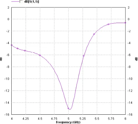
[image:2.612.328.559.458.618.2]The return loss of the proximity coupled fed circular disk patch antenna without slot in the ground plane simulated on IE3D as shown in figure 3
Figure 3: Return loss variation with frequency of the antenna
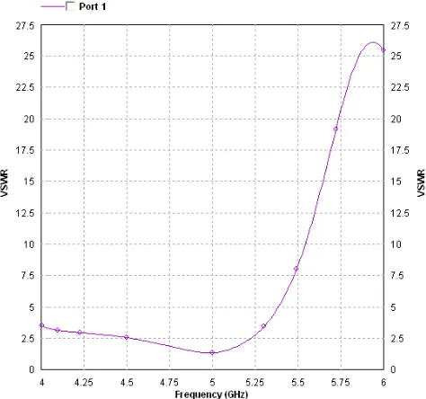
The VSWR characteristics of proximity coupled fed circular disk patch antenna without slot in the ground plane as shown in figure 4.
International Journal of Emerging Technology and Advanced Engineering
Website: www.ijetae.com (ISSN 2250-2459, Volume 2, Issue 10, October 2012)128
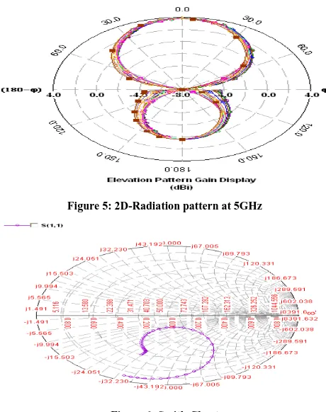
The figure 4 indicates that antenna shows good impedance matching with feed network at 5GHz and VSWR values 1.5 and gain of the antenna is 4dBi. Figure 5 shows the 2D-Radiation pattern of the proximity fed circular disk patch antenna without slot in the ground plane, Figure 6 shows the smith chart of the proximity fed circular disk patch antenna without slot in the ground plane. [image:3.612.327.566.139.290.2][image:3.612.52.282.230.521.2]
Figure 5: 2D-Radiation pattern at 5GHz
Figure 6: Smith Chart
The graph shows above indicates the gain characteristics of the proximity fed circular disk patch antenna without slot in the ground plane at 5GHz with the decibel gain 4 dBi.To achieve the improved performance of proximity fed circular disk patch antenna with slot in the ground plane L=4mm, W=4mm having a same dimensions as that of conventional circular patch antenna as shown figure 7.
Figure 7: Geometry of the proximity fed circular disk micro strip patch antenna with the slot in the ground plane
The optimum performance of antenna is obtained by adjusting the slot on the ground plane which is turn excites the other mode as the electrical length of the antenna is increased. The simulated results shows that the antenna resonates efficiently at 5GHz frequency as shown figure 8
[image:3.612.50.288.240.386.2] [image:3.612.334.552.388.578.2]International Journal of Emerging Technology and Advanced Engineering
Website: www.ijetae.com (ISSN 2250-2459, Volume 2, Issue 10, October 2012) [image:4.612.327.553.142.365.2]129
In the presence of slot in the ground plane the dominant mode of proximity fed circular patch are affected that perturb the uniform current distribution on the patch surface and the electrical length of the antenna is increased and which shows good impedance matching with feed network and also bandwidth improvement at 5GHz. The antenna now has the % bandwidth at 5GHz as 7.5%. The VSWR of proximity fed circular disk patch antenna with the slot in the ground plane as shown figure 9.Figure 9: VSWR variation with the frequency of the antenna
Figure 10 shows the 2D-Radiation pattern of the proximity fed circular disk patch antenna with slot in the ground plane, Figure 11 shows the smith chart of the proximity fed circular disk patch antenna with slot in the ground plane.
Figure 10: 2D-Radiation pattern at 5GHz
[image:4.612.52.289.249.471.2]International Journal of Emerging Technology and Advanced Engineering
Website: www.ijetae.com (ISSN 2250-2459, Volume 2, Issue 10, October 2012)130
III. DISCUSSION
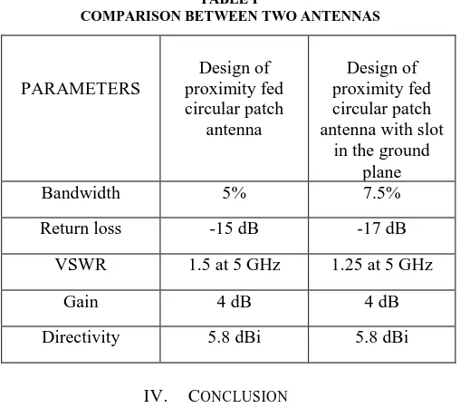
[image:5.612.42.296.369.594.2]The performance characteristics of two antenna i.e., proximity fed circular disk patch antenna without slot in the ground plane and proximity fed circular disk patch antenna with slot in the ground plane simulated under similar condition has been tabulated in the table 1.In order to improve the performance of proximity fed circular disk patch antenna with slot in the ground plane of specific dimensions has been located at different position on the circular disk patch antenna and each time resulting antenna has been optimized. The antenna performance degrades if the slot in the ground plane is located at other position rather than for this design in this paper. It is clear that from table 1, the overall performance of proximity fed circular disk patch antenna with slot in the ground plane is higher than proximity fed circular disk patch antenna without slot in the ground plane. The operating bandwidth at this resonance has considerable higher than the antenna without slot in the ground plane
TABLE I
COMPARISON BETWEEN TWO ANTENNAS
PARAMETERS Design of proximity fed circular patch antenna Design of proximity fed circular patch antenna with slot
in the ground plane
Bandwidth 5% 7.5%
Return loss -15 dB -17 dB
VSWR 1.5 at 5 GHz 1.25 at 5 GHz
Gain 4 dB 4 dB
Directivity 5.8 dBi 5.8 dBi
IV. CONCLUSION
In this paper the performance of proximity fed circular disk patch antenna with the slot in ground plane has been discussed. Proximity fed has been used to excite the antenna. Proximity fed circular disk patch antenna with slot in the ground plane improvement in bandwidth and are having better return loss and reduction in size also achieved.
The new feed system will further improve antenna performance in terms of gain and VSWR, which plays major role during coupling of power from transmitter to space. The proposed structure will also improve various quality parameters of the antenna and improve overall performance of the radiating system.
REFERENCES
[1 ] C. A. Balanis, “Antenna Theory”, Analysis and Design 3rd edition,”
John Wiley & Sons, Inc.,2005.
[2 ] John D.Kraus. “Antenna & propagation", Mc Graw –Hill international Editions, 2 edition 1988.
[3 ] Prabhakar Singh, Dheeraj Kumar, “Analysis & Design of L-strip Proximity & Circular Disk Patch Antenna”, IEEE Trans. on Antennas and Propagation ,Vol.No.2, pp March 2011
[4 ] IE3D simulation software, Zeland, version 14.05,2008.
[5 ] D. M. Pozar, Microwave and RF Design of Wireless Systems, John Wiley & Son, Inc, 2001.
[6 ] Abhishek Choubhey,Dinesh Kumar Singh,”Parallel Slot Loaded Proximity Coupled Microstrip Antenna for wireless communication” IJESET vol.2,issue 1,pp 37-45, April 2012.
[7 ] Wayne S.T.Rowe,Rod B.Waterhouse,”Investigation into the performance of proximity coupled stacked patches” IEEE Transcations on Antennas & prop.,vol 54,no.6 pp 1693-1698,jun 2006.
[8 ] Steven (Shichang) Gao, Alistair sambell,”Dual polarized broad band microstrip antenna fed by proximity coupling “ IEEE Transcation on Antennas & prop., vol 53,no.1 pp 526-530,jan 2005.
[9 ] Shubham Gupta, Shilpa Singh,”Bandwidth Enhancement in multilayer microstrip proximity coupled array”IJECSE,vol.1,no.2,pp 287-293.
[10 ]Milind Thomas, Vikas Chelani, Rahul Ramesh, Sanjay Sukumar, Saurav Singh,” Inclined slot loaded proximity coupled microstrip antenna for WLAN” UARJ vol.1, issue1,pp 1-3,2012.
[11 ]Ramesh Kumar, Gian Chand, Monish Gupta, Dinesh Kumar Gupta,”Circular Patch Antenna with enhanced bandwidth using narrow rectangular slit for WI-MAX Application”,IJECT vol.1,issue 1,pp 43-48 Dec.2010
[12 ]Yong –Xin Guo, Chi Lun Mak, Kwai-Man Luk,Kai-Fong Lee,”Analysis & Design of L-probe proximity fed patch antennas” IEEE Trans. On Antennas & Prop. Vol.49 no.2 pp 145-149,feb 2001. [13 ]Amit A.Deshmukh, K.P.Ray,”Broadband Proximity fed Modified Rectangular Microstrip Antenna”,IEEE Antenna & Prop. Vol.53,no.5,pp 41-56,October 2011.
[14 ]Ramesh Kumar,Gian Chand,Monish Gupta,Dinesh Kumar Gupta,”Circular Patch Antenna with enhanced bandwidth using narrow rectangular slit for WI-MAX Application”’IJECT vol.1,issue 1,pp 43-48,Dec 2010.
[15 ]Nasimuddin, Xianming Qing, Zhi Ning Chen, “Microstrip Antenna with S-Shaped Slot for Dual-Band Circularly Polarized Operation” in proceedings of the European Microwave Conference, EuMC, 2009, pp. 381-384.
International Journal of Emerging Technology and Advanced Engineering
Website: www.ijetae.com (ISSN 2250-2459, Volume 2, Issue 10, October 2012)131
[17 ]Nassimudin & Z.N.chen,”Wideband multilayered antennas fed by Coplanar waveguide-loop with & without via combination,” IET Microwave antennas propag., Vol.3, pp 85-91, 2009.
[18 ]Prajapati,P.R;Kartikeyan,M.V,”Proximity coupled stacked circular disc microstrip antenna with reduced size & enhanced bandwidth using DGS for WLAN/WIMAX application (SCEECS) IEEE, pp 1-4,2012.
[19 ]Mathur,R; Joshi,S, “A novel multiple elements patch antenna for wireless MIMO beam forming & WIMAX applications ETNCC IEEE, pp 110-114,2011.