© 2018, IRJET | Impact Factor value: 6.171 | ISO 9001:2008 Certified Journal | Page 2302
OPTIMISATION TECHNIQUE FOR DESIGN AND FABRICATION OF ASTM
BASED MULTITHICKNESS DIE
Mr.N. Manikandan
1, Mr.V.P. Sureshkumar
1, S. Mithun Rupak
2, J. Vishnuraja
2, Y.G. Sterbin Jeso
21 Assistant professor, P.A. College of Engineering and Technology, Pollachi, Coimbatore, Tamilnadu, India 2 U.G Scholar, P.A. College of Engineering and Technology, Pollachi, Coimbatore, Tamilnadu, India
---***---Abstract -
This manufacturing of ASTM based multi thickness pass on with variable thickness. The current monetary situation makes the use of exceptionally prepared men exorbitant to be joined into the assembling business. Our venture consequently makes the assembling of ASTM testing parts of different measurements in single kick the bucket therefore lessening the cost of buying numerous bites the dust for various thickness. This pass on has three sections which are in particular the male part, holding plate and the female part. The material which is to be delivered in required measurements will be included the bite the dust and it is packed by outer load. The key element of this variable measurement pass on is to differ the thickness of the segment by embeddings Sims of relating thickness between the male and female parts of bite the dust. After the curing of the material, the kicks the bucket are part into two sections. This bite the dust could be utilized as a part of different applications that fundamentally centers around a lessening the creation cost of segments.Key Words: ASTM Standards, Multithickness Die, Sims Nozzle
1. INTRODUCTION
Compression Molding is a well-known technique to develop a variety of composite products. It is a closed molding process with high pressure application. Compression mould dies are manufactured in a variety of size. The tools entail of a male mould and female mould nozzles.
Reinforcement and Matrix stay sited in the metal mould and the entire assembly is reserved in among the compression chamber. The die may be definite as the female part of a whole tool for manufacturing work in a press. It is too mentioned to a whole tool contains of a couple of coupling adherents for manufacturing work in a press.
In this procedure, the programmed quantity of custody of material is placed. The material is warmed beforehand implanting into the mould cavity to lessen the temperature variance among the material and the mould cavity. The mould cavity is closed with upper movable half mould and pressure is pragmatic to bandage the material into the mould cavity. This sources the raw material to be embraced available to yield the shape of the mould cavity. There are three significant influences to be measured beforehand compression moulding process:(1) Quantity of
material (charge), (2) Pressure mandatory for squeezing the material into the mould cavity
A die is a particular tool used in manufacturing industries to bowdlerized or shape material typically by means of a press. A like molds, dies remain usually modified to the piece they are castoff to create. Products ended by dies range after modest paper clips to composite pieces castoff in progressive technology.
2. COMPRESSION MOULDING TOOL
Compression mould tool also is known as die or mould. The dies are two types, first one is solitary cavity die and the another one is multi cavity die. For cumulative the making rate with reducing the cost determination, applied multi cavity injection mould. A Tool designed be contingent on confirmed part design dimensions. For tool designing, determination used software is Solid Works, AutoCAD.
2.1 DESIGN OF MULTITHICKNESS DIE
Mould tool is a multi-cavity die that capitals more than one part in a cavity. It covers core plate, a cavity plate, bottom plate, top plate. Tool or die designed based on ASTM standards.
Fig-1. Part drawing
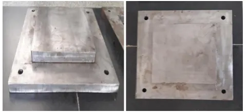
2.2 DESIGN OF CORE PLATE AND BOTTOM PLATE
© 2018, IRJET | Impact Factor value: 6.171 | ISO 9001:2008 Certified Journal | Page 2303 150*150*10 mm. and at bottom of the plate, it is drilled and
threaded for 5mm in four corners maintain at a center distance for guideline purpose. Then the bottom plate is also a simple plate which is machined to 250*250*10mm.In this plate, the same process of drilling and treading is done corresponding to the core plate.
2.3 DESIGN OF CAVITY PLATE
There is not any design in Cavity plate since of the entire portion design transpires in core plate itself. Nearly all die contains cavity plate and top supporting plate, but in this project, we are providing a thick cavity plate without providing top supporting plate. In which the cavity plate is removed by milling 150*150*10 mm from a Centre portion of 250*250*10.
3. TOOL MANUFACTURING PROCESS
Some of the sequential steps having to manufacture the multi cavity die; the navigating steps are Raw material selection, Pre-machining, DRO Milling, Surface Grinding, phasing, drilling, chamfering, threading, Polishing, and Assembly.
Table -1: Raw material sizes of tool components
Material
Purpose Height (mm Width (mm) Thickness (mm)
Core Plate 10 150 150
Bottom plate 10 250 250
Cavity plate 10 250 250
Top plate 10 250 250
3.1 TOOL OR DIE COMPONENTS
The tool contains a core, cavity, bottom plate and return pins. In Compression mould tool core plate is used to attach the entire product design and also attached leader bush and return pins. Generally, in cavity plate is used to hold the cavity side of the product. But here in this project, the selected part contains flat surface and thinner because of this nothing is designed about part related in cavity plate, just used as a support plate.
[image:2.595.323.544.68.518.2]Designated Mild steel (MS) raw material grounded proceeding the ASTM designed values to design and work the tool. In underneath table comprises raw material sizes of workings of Compression tool. Now metal shape is got by eliminating the unsolicited material after the Work Piece in the procedure of chips.
Fig-2. Core Plate and Bottom Plate
Fig-3. Cavity Plate
Fig-4. Top Plate
3.2 PRODUCT (OR) PART MANUFACTURING
Product producing is only plastic part fabricating by utilizing pressure forming process. Plastic is a decent designing material for generally items. All plastics materials are polymers, these polymers are partitioned into two sorts in that initial one is Thermoplastics and the second one is Thermo sets. Thermoplastic material melts when warmed and changed over and over. Thermo sets solidify when they are warmed, later it will lose their properties. Utilizing Thermoplastic write material for item fabricating, on the grounds that these sort materials are milder,adaptable and it contains low softening point temperature.
3.2.1 STANDARD INJECTION CYCLE TIME
Mould Close : 1-2 sec
[image:2.595.306.549.78.187.2]© 2018, IRJET | Impact Factor value: 6.171 | ISO 9001:2008 Certified Journal | Page 2304 Screw return : 2-5 sec
Mould open : 1 sec
Ejection : 1 sec
The total injection cycle time: 25 – 44 sec this time change depends on product complexity
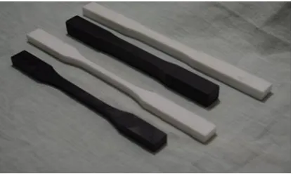
3.2.2 ASTM STANDARDS
ASTM Standards remains an international standards group that matures and issues voluntary agreement practical values for an extensive variety of materials, goods, schemes, and facilities. Certain 12,575 ASTM voluntary agreement values function internationally. The American Section of the International Association for Testing Materials precedes additional standards administrations such as the BSI (1901), IEC (1906), DIN (1917), ANSI (1918), AFNOR (1926), and ISO (1947). ASTM D638 - Standard Test Method aimed at Rate of Scorching and/or Degree and Period of Scorching of composite materials.
[image:3.595.58.267.309.433.2]
Fig-5. Specimen of ASTM D638
3.3 OPTIMIZATION
3.3.1 PROCESS OPTIMIZATION
In this task streamlining procedure can partition into three ways. Initial one is Process Optimization and the second one is Production rate last process is Cost streamlining. A change occurs in machining procedure of center and cavity plate. Add up to part configuration machining center plate itself there no plan cavity plate it is utilized doe bolstered plate for pack and holding process.
Fig-6. Production Process Cycle
3.3.2 COST OPTIMIZATION
The important cost carrying out parameters are injection moulding cycle time, metal and material cost, tooling cost and production cost. For cost optimization certain some factors these factors are given below
3.3.2.1 Total Manufacturing Cost
TMC = M + T + P
TMC = Total Manufacturing Cost M = Material
T= Tooling P = Processing
3.3.2.2 MATERIAL COST PER PART
cM = M/q = (cost/weight x weight)
/ /number of parts cM
= cw (w p + w w) =cw (w p + α wp) cM = cwwp (1+ α) Here, M = Total m
materials costs (raw) Q = production quantity
cM = [cost/weight] [weight/no of P a r P Parts
cM = (cost/weight) (weight/part) cM = cost/part
cw = material cost per unit weight, wp = weight of finished part
ww = weight of wasted material, scrap α = ratio of wasted material weight /
f finished weight α = w w / w p
3.3.4 TOOLING COST PER PART
CT = T/q
T = Total cost of moulds, fixtures per c cycle
Q = Number of parts per run
3.3.5 PROCESSING COST PER PART
CP = Ct .t Where,
Ct = cost per hour, (machine rate + labour) t = cycle time (hours per part)
3.3.6 TOTAL COST PER PART
Cost per part,
C = CM + CT + CP (OR) C = c w wp (1+ α) + T/q + C t t
© 2018, IRJET | Impact Factor value: 6.171 | ISO 9001:2008 Certified Journal | Page 2305 4. RESULTS
Results entered in the following table format, form this easy to estimate cost differences in between single cavity and multi cavity production process.
4.1 DESIGN CALCULATION
Total Area=2(LB+BH+HL) L-length = 250mm H-height = 0-10mm B-breath = 250mm
For Height of 1mm= 2((250*250) + (250*1) + (1*250)) =126000〖mm〗^2
For Height of 2mm= 2((250*250) + (250*2) + (2*250)) =127000〖mm〗^2
For Height of 3mm= 2((250*250) + (250*3) + (3*250)) =128000〖mm〗^2
For Height of 4mm= 2((250*250) + (250*4) + (4*250)) =129000〖mm〗^2
For Height of 5mm= 2((250*250) + (250*5) + (5*250)) =130000〖mm〗^2
For Height of 6mm= 2((250*250) + (250*6) + (6*250)) =131000〖mm〗^2
For Height of 7mm= 2((250*250) + (250*7) + (7*250)) =132000〖mm〗^2
Volume of Total Mould Area=L*B*H
For Height of 1mm= 62500〖mm〗^3 For Height of 2mm= 125000〖mm〗^3 For Height of 3mm= 187500〖mm〗^3 For Height of 4mm= 250000〖mm〗^3 For Height of 5mm= 312500〖mm〗^3 For Height of 6mm= 375000〖mm〗^3
Mould Area=2(LB+BH+HL)
L-length = 150mm H-height = 0-10mm B-breath = 150mm
For Height of 1mm= 2((150*150)+ (150*1)+ (1*50)) =126000〖mm〗^2
For Height of 2mm= 2((150*50)+ (150*2)+ (2*50)) =127000〖mm〗^2
For Height of 3mm= 2((150*50)+ (150*3)+ (3*50)) =128000〖mm〗^2
For Height of 4mm= 2((150*50)+ (150*4)+ (4*50)) =129000〖mm〗^2
For Height of 5mm= 2((150*50)+ (150*5)+ (5*50)) =130000〖mm〗^2
For Height of 6mm= 2((150*50)+ (150*6)+ (6*50)) =131000〖mm〗^2
For Height of 7mm= 2((150*50)+ (150*7)+ (7*50)) =132000〖mm〗^2
Volume of Mould Area=L*B*H
For Height of 1mm= 22500〖mm〗^3 For Height of 2mm= 45000〖mm〗^3 For Height of 3mm= 67500〖mm〗^3 For Height of 4mm= 90000〖mm〗^3 For Height of 5mm= 112500〖mm〗^3 For Height of 6mm= 135000〖mm〗^3 For Height of 7mm= 157500〖mm〗^3 For Height of 8mm=180000〖mm〗^3
5. CONCLUSION
In this work the composite material mould die was produced and gathering in lucratively. Before that while plates and materials cutting machining, the fiber was detached and pull from the roundabout clear. This issue prompts influence the execution and mechanical properties of plates and materials. With a specific end goal to maintain a strategic distance from that in this work we fabricated the composite plates and materials mould die for the same. Contrasted with a conventional method for assembling plates and materials in this write we can take out poor surface complete, fiber remove and fiber pulls. The greatest
preferred standpoint of this procedure is no machining is required so machining expense will be diminished.
ACKNOWLEDGEMENT
We sincerely thank Principal & Chairman of P. A college of Engineering and Technology for providing us the laboratory equipment to ensure our project and we also thank our Faculty members Mr.N. Manikandan and Mr.V.P. Suresh Kumar from the department of mechanical Engineering at P.A college of Engineering and technology for their valuable guidance’s.
REFERENCES
[1] Shigeyuki Maruyama “Influence of Surface roughness on leakage of new metal Gasket”, International Journal of Pressure Vessels and Piping, Volume.111, Pages.146-154, 2013.
© 2018, IRJET | Impact Factor value: 6.171 | ISO 9001:2008 Certified Journal | Page 2306 and Submarine Gate”,Procedia Engineering, Volume.64,
Pages 1310-1319, 2013.
[4] Wang, Yi-Qi & Kim, Jae-gyu& Song, Jung-il., “Optimization of plastic injection molding process parameters for manufacturing a brake booster valve body”, Materials & Design. Volume.56, Pages. 313–317, 2014.
[5] Sampath.A, Hemanth.R, “Conceptual Design of Injection Mould Tool for The Chair Hand Rest Component”, International Journal of Research in Engineering and Technology, Volume.3, Issue.3, Pages.791-794, 2014.
[6] V. P. Suresh Kumar, N. Manikandan, M. Jayaraj “Design and Analysis of Ultrasonic Welding Horn using Finite Element Analysis”, International Journal of Engineering Science Technology and Research (IJESTR), Volume-2, Issue-3, May - June - 2017, Page No. 74 – 87.
BIOGRAPHIES
Mr.N.Manikandan , Assistant professor at P.A College of Engineering and Technology. His research interest includes Nanoparticles, Materials.
Mr.V.P. Suresh Kumar, Assistant professor at P.A College of Engineering and Technology. His research interest includes Nanoparticles, Refrigeration Syatems.
S.Mithun Rupak, U.G Scholar at P.A College of Engineering and Technology. His interest includes Design, Materials.
[3] JagannathaRao M B, Ramni, "Analysis of Plastic Flow in Two Plate Multi Cavity Injection mould for Plastic Component for Pump Seal”, International Journal of Scientific and Research Publications, Volume 3, Issue 8, 2013.
Y.G.Sterbin Jeso, U.G Scholar at P.A College of Engineering and Technology. His interest includes Nanoparticles, Refrigeration Syatems.