© 2018, IRJET | Impact Factor value: 6.171 | ISO 9001:2008 Certified Journal | Page 3852
Hampered Serving Bot
V.Indhu
1, P.Divya Bharathi
2, B.Priyanka
3, C.Murugan
4, Prof.L.Manivannan
51, 2, 3, 4, 5 Electrical and Electronics Engineering, Knowledge Institute of Technology, Kakapalayam,
Salem-637 504,Tamil Nadu.
---***---ABSTRACT-In many industries wireless operations are needed in dangerous or hazardous areas. In some industries it is mandatory to handle few jobs with very high temperature which is not possible by human hand .In such cases wireless operations are more efficient. This paper focuses on design of gesture controlled wheel chair using microcontroller with the help of Bluetooth and wireless sensor networks. Programming for the controller is being carried out and the hardware prototype was successfully implemented with the necessary requirements. It provides new trends in technology, application and usability. We present an integrated approach in real time detections, gesture based data which control vehicle movement of the wheel chair and manipulation on gesture using hand movements and voice recognition. Today Human machine Interaction is becoming pervasive and much compatible with the physical world. With each passing day the gap between machines and human is being reduced with the introduction of new technology. It makes the standard of living easier.
Keywords: Bluetooth module, Mobile application, Accelerometer sensor, Wheel Chair.
1. INTRODUCTION
Hampered Serving bot serves the physically challenged people in dual purpose. First is through voice recognition. It is especially for the people who don’t have legs but they can speak Voice recognition can be done through mobile application which is interfaced with the Bluetooth module. Second purpose is, it can be applicable for those who have disability in speaking and can’t walk. This can be made possible with the help of gesture movements captured from the user.
Gesture controlled system, human hand movements are sensed by the robot through sensors. As the person moves their hand, the accelerometer also moves accordingly as per the instructions given by the user.
This model Hampered Serving bot is developed, in which the vehicle movements and manipulations i.e., handling and control is controlled depending on the gesture of the user and the voice commands recognized from the user. Programming is developed for fixing the direction angle. By this system; it is possible to achieve controlling of wheel chair without manually. This system is knowingly developed to apply for the special purpose of wheel chair control without manually.
2. EXISTING SYSTEM
In this world where every operations performed by human are getting simple, in order to make it simpler the very definition of being human. The Existing systems are based on hand gestures which will be useful for squad communication. The current hand signal system for soldiers has some shortages, such as unavailability in the darkness and sometimes hard to keep stealth. It will be also applicable for patient’s emergency in hospital, security purpose. The transceiver will be able to detect several hand gestures and then send out thecorresponding information, which will finally be received by another transceiver or computer and displayed on a LCD screen.
3. PROPOSED SYSTEM
The Proposed system of Hampered serving bot has been developed for dual purpose. The main motto of developing this product is to serve the physically challenged people. The People who don’t have legs are suffering a lot to pull and move the wheel chair. Normally, they have to use their hands which are difficult for them. Many advanced technologies are being developed to help the physically challenged people. But this product has a special theme of helping them in dual manner.
Voice Recognition
Gesture Control
Voice Recognition:
Voice of the user is being recognized using mobile application which is interfaced with the Bluetooth module. The recognized voice is sent as a command to the PIC microcontroller. It will then control the vehicle movement using driver circuit.
The requirements for voice recognition control are mobile application, Bluetooth module and microcontroller. Java application has been developed in the mobile phone. The voice will be recognized from the user and the command will be transmitted to the device fixed in the wheel chair through the Bluetooth module.
© 2018, IRJET | Impact Factor value: 6.171 | ISO 9001:2008 Certified Journal | Page 3853 Elements of Speech to command conversionary
Speech Acquisition
Speech conversion
Transmission
Bluetooth Module:
Bluetooth is a wireless technology used for transmitting or exchanging data, information’s, files, applications, etc. over short distances from fixed devices. Thereby Bluetooth is building a personal area networks. Bluetooth usually covers a short distance range of 40-400 meters i.e. about 100-1000 feet. The wavelength is about 2.4 to 2.48 GHz. Bluetooth is a cable replacement technology. It connects one device to another with a short range radio link. It usually consists of a single master device and one or two slave devices.
[image:2.595.336.536.96.230.2]The main purpose of Bluetooth in Hampered serving bot is to act as a transmitter and receiver system. It is mainly used in the voice recognition part where the voice command has to be received from the user as well as it has to be send to the microcontroller as a commanding signal.
Fig 1: Bluetooth Module
Gesture Control:
Gesture of the user is detected using the Accelerometer sensor. By using this gestures vehicle movement can be controlled. The Accelerometer sensor fixed in the gloves is fixed in the user hand. According to the hand movement of the user the vehicle movement is controlled.
The requirements for gesture control are Accelerometer sensor, amplifier and microcontroller. A common sensing approach used in accelerometers is capacitor sensing in which acceleration is related to the change in the capacitance of moving mass. It is known for its high accuracy, stability, low power dissipation and simple structure to built. It is not prone to noise and variation with temperature. An op amp process small, differential mode signals appearing between its two input signals, developing a single ended output signal referred to a power supply common terminal.
Fig 2:Gesture Control
This Proposed System gesture based system controls the vehicle movement and manipulation on gesture of the user using hand movements. A three axis accelerometer is adaption. As the person moves their hand, the accelerometer also moves accordingly. The gesture is capture by accelerometer and processed by gesture. Today human machine interactions is moving away from mouse and pen and is becoming pervasive and much mouse compatible with the physical world . With each passing day the gap between machines and human is being reduced with the introduction of new technology is easy the standard of living. Its having future scope of advanced robotic arms that are designed like the human hand itself can easily controlled using hand gesture only.
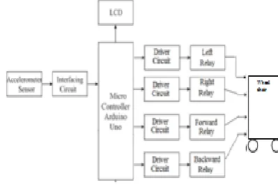
4. BLOCK DIAGRAM
Fig 3: Methodology for hand motion recognition
The handheld controller is a 3D rigid body that can be rotated about the three orthogonal axes. Yaw, pitch and roll are referred to as rotation. These rotation takes place as Z axis is called yaw, the next rotation X-axis is called pitch and last rotation about the Y-axis is called roll. Any orientation can be achieved by the composing those three elemental rotation. In our work, all of the planned hand motions for robot control are simple gestures, each of which contains only one of the three elemental rotations. Gestures composed of more than one elemental rotation are too complicated for such kind of application.
[image:2.595.78.260.382.479.2] [image:2.595.326.540.479.567.2]© 2018, IRJET | Impact Factor value: 6.171 | ISO 9001:2008 Certified Journal | Page 3854 perform their operations with direct human guidance;
intelligent spy robot project has been designed for the spying purpose
Moves in forward direction
Moves in reverse direction,
It can even turn left or right while moving forward or in reverse direction.
Accelerometer sensor
PIC microcontroller
LCD display
Relay(4)
Wheel chair
Bluetooth Module
Amplifier
Accelerometer Sensor:
A Common sensing approach used in accelerometer sensors is capacitance sensing. The acceleration is related to the change in moving mass capacitance. The advantages of using the accelerometer sensors are high accuracy, Stability, low power dissipation and simple in structure to construct. It does not give negative effect to noise and temperature variations. It has the air trapped inside the IC that acts as a damper. Due to this the bandwidth for a capacitive accelerometer is only a few hundred Hertz.
C= (ε0 × εr × A)/D (Farad)
ε0= Permitted free space
εr = Relative material permitted between plates A= Area of overlap between electrodes
D= Separation between the electrodes
CONCEPTS OF MICROCONTROLLER:
Microcontroller is a general purpose device, which integrates a number of the components of a microprocessor system on to single chip. It has inbuilt CPU, memory and peripherals to make it as a mini computer. A microcontroller combines on to the same microchip:
The CPU core
Memory(both ROM and RAM)
Some parallel digital i/o
Microcontrollers will combine other devices such as:
A timer module to allow the microcontroller to perform tasks for certain time periods.
A serial I/O port to allow data to flow between the controller and other devices such as a PIC or another microcontroller.
An ADC to allow the microcontroller to accept analogue input data for processing.
Microcontrollers are:
Smaller in size
Consumes less power
Inexpensive
Micro controller is a standalone unit, which can perform functions on its own without any requirement for additional hardware like I/O ports and external memory.
The heart of the microcontroller is the CPU core. In the past, this has traditionally been based on an 8-bit microprocessor unit. For example Motorola uses a basic 6800 microprocessor core in their 6805/6808 microcontroller devices.
In the recent years, microcontrollers have been developed around specifically designed CPU cores, for example the microchip PIC range of microcontrollers. The microcontroller that has been used for this project is from PIC series. PIC microcontroller is the first RISC based microcontroller fabricated in CMOS (complementary metal oxide semiconductor) that uses separate bus for instruction and data allowing simultaneous access of program and data memory.
The main advantage of CMOS and RISC combination is low power consumption resulting in a very small chip size with a
Accelerometer sensor
PIC microcontroller
LCD display
Relay(4)
Wheel chair
Bluetooth Module
Amplifier
Accelerometer Sensor:
A Common sensing approach used in accelerometer sensors is capacitance sensing. The acceleration is related to the change in moving mass capacitance. The advantages of using the accelerometer sensors are high accuracy, Stability, low power dissipation and simple in structure to construct. It does not give negative effect to noise and temperature variations. It has the air trapped inside the IC that acts as a damper. Due to this the bandwidth for a capacitive accelerometer is only a few hundred Hertz.
C= (ε0 × εr × A)/D (Farad)
ε0= Permitted free space
© 2018, IRJET | Impact Factor value: 6.171 | ISO 9001:2008 Certified Journal | Page 3855 A= Area of overlap between electrodes
D= Separation between the electrodes
CONCEPTS OF MICROCONTROLLER:
Microcontroller is a general purpose device, which integrates a number of the components of a microprocessor system on to single chip. It has inbuilt CPU, memory and peripherals to make it as a mini computer. A microcontroller combines on to the same microchip:
The CPU core
Memory(both ROM and RAM)
Some parallel digital i/o
Microcontrollers will combine other devices such as:
A timer module to allow the microcontroller to perform tasks for certain time periods.
A serial I/O port to allow data to flow between the controller and other devices such as a PIC or another microcontroller.
An ADC to allow the microcontroller to accept analogue input data for processing.
Microcontrollers are:
Smaller in size
Consumes less power
Inexpensive
Micro controller is a standalone unit, which can perform functions on its own without any requirement for additional hardware like I/O ports and external memory.
The heart of the microcontroller is the CPU core. In the past, this has traditionally been based on an 8-bit microprocessor unit. For example Motorola uses a basic 6800 microprocessor core in their 6805/6808 microcontroller devices.
In the recent years, microcontrollers have been developed around specifically designed CPU cores, for example the microchip PIC range of microcontrollers.
The microcontroller that has been used for this project is from PIC series. PIC microcontroller is the first RISC based microcontroller fabricated in CMOS (complementary metal oxide semiconductor) that uses separate bus for instruction and data allowing simultaneous access of program and data memory.
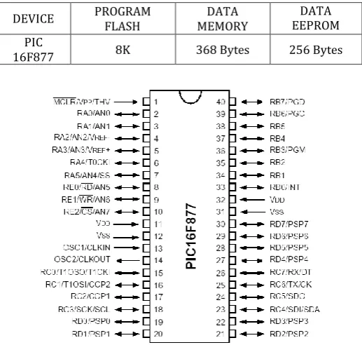
The main advantage of CMOS and RISC combination is low power consumption resulting in a very small chip size with a small pin count. The main advantage of CMOS is that it has immunity to noise than other fabrication techniques. PIC (16F877):
Various microcontrollers offer different kinds of memories. EEPROM, EPROM, FLASH etc. are some of the memories of which FLASH is the most recently developed. Technology that is used in pic16F877 is flash technology, so that data is retained even when the power is switched off. Easy Programming and Erasing are other features of PIC 16F877.
Fig 4: PIC 16F877
ACCELEROMETER:
An accelerometer is a device that measures proper acceleration, the acceleration experienced relative to free-fall. Single- and multi-axis models are available to detect magnitude and direction of the acceleration as a vector quantity, and can be used to sense orientation, acceleration, vibration shock, and falling. Micro machined accelerometers are increasingly present in portable electronic devices and video game controllers, to detect the position of the device or provide for game input.
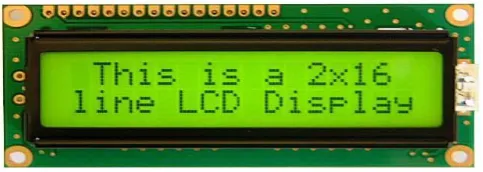
LCD DISPLAY
Liquid crystal displays (LCDs) have materials which combine the properties of both liquids and crystals. Rather than having a melting point, they have a temperature range within which the molecules are almost as mobile as they would be in a liquid, but are grouped together in an ordered form similar to a crystal.
An LCD consists of two glass panels, with the liquid crystal material sand witched in between them. The inner surface of the glass plates are coated with transparent electrodes which define the character, symbols or patterns to be displayed polymeric layers are present in between the
DEVICE PROGRAM FLASH MEMORY DATA EEPROM DATA
PIC
[image:4.595.306.565.177.423.2]© 2018, IRJET | Impact Factor value: 6.171 | ISO 9001:2008 Certified Journal | Page 3856 electrodes and the liquid crystal, which makes the liquid
crystal molecules to maintain a defined orientation angle.
One each polarizers are pasted outside the two glass panels. These polarizers would rotate the light rays passing through them to a definite angle, in a particular direction
When the LCD is in the off state, light rays are rotated by the two polarizers and the liquid crystal, such that the light rays come out of the LCD without any orientation, and hence the LCD appears transparent. When sufficient voltage is applied to the electrodes, the liquid crystal molecules would be aligned in a specific direction. The light rays passing through the LCD would be rotated by the polarizers, which would result in activating / highlighting the desired characters.
[image:5.595.39.281.507.593.2]The LCD’s are lightweight with only a few millimeters thickness. Since the LCD’s consume less power, they are compatible with low power electronic circuits, and can be powered for long durations. The LCD does don’t generate light and so light is needed to read the display. By using backlighting, reading is possible in the dark. The LCD’s have long life and a wide operating temperature range. Changing the display size or the layout size is relatively simple which makes the LCD’s more customer friendly. The LCDs used exclusively in watches, calculators and measuring instruments are the simple seven-segment displays, having a limited amount of numeric data. The recent advances in technology have resulted in better legibility, more information displaying capability and a wider temperature range. These have resulted in the LCDs being extensively used in telecommunications and entertainment electronics. The LCDs have even started replacing the cathode ray tubes (CRTs) used for the display of text and graphics, and also in small TV applications.
Fig 5: LCD Display
POWERSUPPLY:
The power supply should be of +5V, with maximum allowable transients of 10mv. To achieve a better / suitable contrast for the display, the voltage (VL) at pin 3 should be adjusted properly.
A module should not be inserted or removed from a live circuit. The ground terminal of the power supply must be isolated properly so that no voltage is induced in it. The module should be isolated from the other circuits, so that
stray voltages are not induced, which could cause a flickering display.
RELAY DRIVER CIRCUIT:
In electronics, a driver is an electrical circuit or other electronic component used to control another circuit or other component, such as a high-power transistor. The term is used, for example, for a specialized computer chip that controls the high-power transistors in AC-to-DC voltage converters. An amplifier can also be considered the driver for loudspeakers, or a constant voltage circuit that keeps an attached component operating within a broad range of input voltages.
The following circuit will allow you to drive a 12V relay using logic voltage (an input of 4V or greater will trip the relay). The circuit has its own 12V power supply making itself contained but the power supply portion can be left out if an external supply will be used. The circuit shows an output from the power supply that can be used to power other devices but it should be noted that the supply is unregulated and not particularly powerful with the parts stated. The 12V DC output is suitable for powering a few LEDs or low voltage lights but should not be used to power other electronic boards or motors.
ROBOT:
A robot is an automatically guided machine which is able to do tasks on its own, almost always due to electronically-programmed instructions. Another common characteristic is that by its appearance or movements, a robot often conveys a sense that it has intent or agency of its own.
This task comprises efforts to research and develop robot team and sensor-detection technologies in support of the Marine Expeditionary Rifle Squad (MERS). As a force multiplier for the MERS, robot teams can be equipped with other promising technologies proposed under this focus group. These technologies include reliable and high-performance UV optical sensors to provide the ability to rapidly detect fire, flame, and explosions. Also, robot teams can be equipped with lightweight, reliable, and hand-held-sized sensors able to detect small concentrations of chemical warfare agents and explosives – a vital asset to detect industrial and chemical toxins during the conduct of urban military operations.
5. CONCLUSION
The progress in science & technology is a non-stop process. New things and new technology are being invented. As the technology grows day by day, we can imagine about the future in which thing we may occupy every place.
© 2018, IRJET | Impact Factor value: 6.171 | ISO 9001:2008 Certified Journal | Page 3857 in mind about the need for physically challenged people, it
can extended for other purposes such as commercial & research applications. Due to the probability of high technology (Atmel microcontroller) used this “Hampered Serving Bot” will help the physically challenged people in a better way. The feature makes this system is the base for future systems.
REFERENCES
[1] R.Raja Prabhu , “ DESIGN OF ROBOTIC ARM BASED ON HAND GESTURE CONTROL SYSTEM USING WIRELESS SENSOR NETWORKS”, International Research Journal of Engineering and Technology (IRJET) e-ISSN: 2395 -0056 Volume: 04 Issue: 03 | March -2017.
[2] Surbhi Mittal, “HAND GESTURE RECOGNITION BASED ROBOT USING ACCELEROMETER SENSOR”, International Journal of Advanced Research in Electrical, Electronics and Instrumentation Engineering (An ISO 3297: 2007 Certified Organization) Vol. 4, Issue 5, May 2015.
[3] Priya Matnani , “GLOVE BASED AND ACCELEROMETER BASED GESTURE CONTROL”, International Journal of Technical Research and Applications e-ISSN: 2320-8163, www.ijtra.com Volume 3, Issue 6 (November-December, 2015), PP. 216-221.
[4] H S Bawiskar, “A REVIEW ON APPROACHES TO DEVELOP GESTURE AND VOICE RECOGNITION TECHNIQUE FOR ROBOT CONTROL “,ISSN 2278 – 0149 www.ijmerr.com Vol. 2, No. 3, July 2013.