DESIGN AND MODELLING OF ELECTRICAL MACHINE FOR
CEILING FAN SYSTEM
N. F. Zulkarnain, T. Ibrahim and H. Z. Hashim
Department of Electrical and Electronic Engineering, Universiti Teknologi Petronas, Perak, Malaysia E-Mail: [email protected]
ABSTRACT
The purpose of this research is to conduct an empirical research to design the electrical machine of a ceiling fan system purposely to generate additional electrical power. The conventional single-phase ceiling fan using an induction motor has a lower 30% efficiency. In addition, the wasted kinetic energy from the mechanical rotor rotation can be converted from mechanical energy to electrical energy. Literature review on topologies of an electrical machine, ceiling fan technologies, previous research on ceiling fan and air gap configurations was systematically analyse in order to obtain the optimum proposed designs configuration. In this research, the permanent magnet machine configuration was selected to propose two designs of ceiling fan machine. The newly introduced design concept in this study is the use of concept single rotor double stator that combining the motor and generator in one system. In this research, Finite Element Analysis (FEA) has been performed to justify and to compare the outcome of the proposed designs using the An soft Maxwell software by analysing the induced voltage, flux linkage, flux distribution and air gap flux density.The selected optimized design will be used to develop a prototype for validating the procedure between the simulation result and experimental result.The testing of the prototype will be conducted experimentally to validate the output with the conventional ceiling fan in term of output power, efficiency and speed.
Keywords: permanent magnet, ceiling fan, back EMF.
INTRODUCTION
The energy usage for each building and household are affected by the usage of electrical appliances, such as lighting system, electronic appliances and cooling appliances which carries high electricity consumption. However, the rate of energy electricity consumption is depends on surrounding factor for instance occupant, management, environmental standard, building design and construction, mechanical and electrical equipment and climate [1]. Realising the importance of the electricity towards the development of the country, Malaysian government had taken the initiatives to increase the generation of electricity in the country.
Energy harvesting can be defined as a process of which the energy is derived and capture to generate electrical energy [2]. Energy can be harvested in many ways such as electromagnetic energy, solar energy, thermal energy or body heat, light energy, mechanical energy etc. [3] [4] [5] [6]. A small amount of energy that
can be captured could be useful to generate additional electricity.
Figure-1 shows the daily usage of electrical appliances in hours for various household electrical appliances in Malaysia [7]. As will be seen, the air conditioner and ceiling fan are classified as the most usage electrical appliances per day. Considering the climate and temperature in Malaysia can reach up to 30° C during daytime, people prefer to use these two applications as a cooling appliance.
The power consumption of each electrical appliances are varies by the power rating, depends on the amount consumed energy and the usage time of the appliances. Figure-2 highlights the yearly energy consumption of each electrical appliance in kWh [7]. Even though the usage time of air conditioner is lower than electrical fan, the energy consumption of air conditioner is 42% higher compared to electrical ceiling fan because of the high power rating.
Figure-1. Daily usage of electrical appliance in hours [7].
Figure-2. Yearly electricity consumption [7].
In a developed country, ceiling fan has become one of the most preferred cooling appliances, especially for hot-warm climate country, Malaysia. The ownership of ceiling fan for each household in Malaysia increasing each year as the development of the residential area over the country growing up rapidly. In relation to that, ceiling fan had contributed significantly to electricity consumptions in Malaysia, especially to residential area.
Most of the electrical appliances and devices had an improvement in term of efficiency to decrease the power rating so that the electricity consumption can be reduced, thus reducing the costing for electricity bill. The improvement of performance in ceiling fan motor is important in the battle against the rising of global temperature and the increasing demand of cooling appliances. The ceiling fan must be high in efficiency and also energy saving. The standard electric ceiling fan using single-phase induction motor and has a low efficiency,
consequently affect the performance of the motor [8], [9].Various types of ceiling fan motor had been improvised beginning from the conventional ceiling fan invented a century ago [10]. One of the inventor C. M. Liu [11] had invented a single-phase induction motor of ceiling fan with bi-directional control that can change the direction of motor using a remote controller. Another type of ceiling fan with outer rotor DC brushless motor was invented by Y. F. Tang [12] consist of a centre base with multiple blades and a DC brushless motor as a driving source had increased the efficiency of the ceiling fan motor.
Generally, conventional ceiling fan is driven by a single-phase induction motor with 30% efficiency [13]. This value of efficiency is not sufficient enough for the performance of the ceiling fan motor. Many researchers have developed a few methods and came out with a prototype of ceiling fan with better-quality output 0,45
0,47 0,47 0,59 0,61 0,93
1,12 1,2 1,36 1,68
3,76 4,23 4,68 4,87
5,43 5,9 6,37 7,91
8,23 18,87
24
0 5 10 15 20 25 30
Hair dryer Toaster Mixer Electric kettle Rice cooker Incandescent lamp Dekstop PC Compact fluorescent lamp Stand fan Television Refrigerator
14 23 23 36 42 51
55 75 84 93
122 150 216 241
242 244 366
369 597
670 1167
0 200 400 600 800 1000 1200 1400
efficiency and energy saving. A research was carried out by M.Fazil and K. R. Rajagopal [13], [14] to develop a single-phase permanent magnet brushless DC (PM BLDC) motor for high volume domestic appliances such as ceiling fan. Another type of ceiling fan that is using brushless DC motor was improved by L. Chuan-Sheng and H. Jonq-Chin [15] had increased the performance of ceiling fan motor and energy saving up to 50%. Moreover, L. Chuan-Sheng et al [16] also developed the new structure of permanent magnet synchronous ceiling fan motor that are high in efficiency and energy saving. In a different perspective, a parametric studied of conventional ceiling fan motor was demonstrated by M. A. Afaq et al [17] to improve the flow field variables and field efficiency. The output testing included the velocity profile, mass flow rate, rated air delivery and torque by varying the rake angle of the blade. Numerous researches were done to improve the operating or the controlling system as well as the efficiency of the ceiling fan motor. Each type of motor has their own strengths and weaknesses depending on the input system, model design and also the applications.
Motor is a machine that converts the input of electrical energy to mechanical energy or kinetic energy. As been discussed before, energy can be harvested from the mechanical energy or kinetic energy. Therefore, the wasted kinetic energy from the mechanical rotor rotation can be converted from mechanical energy to electrical energy (as shown in Figure-3), consequently generate the additional electrical power. Moreover, the efficiency of the ceiling fan motor can be improved by using different topologies of electrical machine. This research will assesses the topologies of electrical machine specifically for rotary motor, present comprehensive analysis and performance predictions, and validated result by experimental measurements.
Figure-3. Conceptual design.
Objective of the research
The major objective for this research is to design and modelling of electric ceiling fan which can convert the kinetic energy to electrical energy. The others sub-objectives are:
i) To conduct extensive literature review on various electrical machine technologies of ceiling fan in order to obtain the best design configuration
ii) To propose two new designs of ceiling fan system which consist of motor and generator combined into one system
iii) To simulate and to compare the proposed designs using the finite element analysis (FEA), Ansoft Maxwell
iv) To develop a most promising prototype and perform a comprehensive test to compare the efficiency, speed and output power with the conventional ceiling fan.
LITERATURE REVIEW
Electrical machines type
Different type of electrical machines need to be compared and justified before choosing the most advantageous design and implement it into the electrical machine of the ceiling fan design such as direct current machine, induction machine, synchronous machine and permanent magnet machine. Every machine has their own characteristics and capabilities that compared the level of performance and feasibility for the ceiling fan application [18], [19].
From the comparison on types of electrical machine, the criteria of permanent magnet machine are more suitable for designing the ceiling fan which has high power and torque density. Furthermore, permanent magnet provides a constant excitation and generates a high magnetic flux, thus provides a high efficiency in the range of nominal speed. Permanent Magnet (PM) motors are energy conversion devices that save energy, environment friendly and also come in simple structure and mechanism.
Radial, axial and transverse flux machines
The selected topologies of flux motor configurations are depend on the type of motor application. Axial flux topologies have more advantages such as compact volume because of the less capacity of stator back iron due to slot-less design as well as has higher torque density [24] [25]. However, axial-flux machine are disadvantages for low speed applications and the selection of pole pairs number are restricted due to its geometrical construction [26]. Transverse-flux machines provide a better torque density, nevertheless high in torque ripple and cogging torque effect. Summarizing the aforementioned aspects, radial-flux motor is more conventional and more reliable compared to axial-flux motor and transverse-flux motor due to simple construction and more robust as the conventional ceiling fans are purposely for a mass production[27]. Thus, radial-flux motor appears to offer significant advantages over the others air gap motor configurations.
METHODOLOGY
Basically, there are four stage of case studied that will be performed;To determine the most appropriate topologies of the electrical machines for ceiling fan and studied various methods to obtain the best design configuration of electrical machines for ceiling fan, to propose two new designs, to simulate the proposed design using the finite element analysis Ansoft Maxwell, to develop the prototype based on proposed design parameter and to perform an experiment to validate the results between the simulation predictions and experimental results.
Proposed design
In order to achieve the objectives of the design, some of the design considerations need to be deliberated before designing the proposed design. Design considerations are important to set the limitations of the design based on the requirement and the applications. The design considerations can be partially divided into non-technical and non-technical part. Table1 shows the design considerations and their justifications.
Table-1. Design considerations and justification.
Design considerations Justifications
Technical
Minimum cogging
torque
Cogging torque produce the unwanted noise and vibrations cause by the interaction between the
stator and rotor of permanent magnet. This cogging torque cannot be removed completely, but it
can be minimize.
Justified back EMF
Back EMF increase the apparent resistance of the system thus consumes less
power and increase the efficiency of the system.
Non-technical
Easy to manufacture
Complex design can increase and improve the
design performance, however this ceiling fan is
focusing for mass production. Thus the design
configurations need to be simple and easy to be
manufactured.
High force capability
The capability of the ceiling fan machine must be balance with the power requirement and the system
proficiency.
The proposed designs using a design concept of single rotor double stator where the rotor for motor and generator part will be attached together as one rotor with separate stator and rotates simultaneously. This ceiling fan design will use permanent magnet attached at the rotor for both motor and generator.
The stator motor for ceiling fan will be connected to the power source and directly supply the electricity to the winding at the stator motor. The coil carrying conductor that have the flow of current will generate the magnetic flux at the winding stator. The interaction between the magnetic flux from the stator and the constant magnetic flux from the permanent magnet at the rotor will drives the rotor to rotate. In this case, the electrical energy is converted into kinetic energy.
electricity. In this case, the kinetic energy is converted into electrical energy.
The key dimension of the proposed design must be justified first to ensure that the dimensions of the ceiling fan are acceptable. The key dimensions of the proposed design are the air gap, stator outer and inner diameter, rotor outer and inner diameter, magnet thickness, back iron length and slot depth. Tables 2 and 3 show the operating conditions and initial designs parameters of the proposed ceiling fan motor.
Table-2. Initial design parameters.
Parameters Dimension(mm)
Aluminium Sheet 11
Motor (outer part)
Back iron thickness 15
Stator outer diameter 230
Stator inner diameter 146
Number of pole/slot 6/12
Slot angle 2
Air gap 1
Permanent magnet thickness 5
Stator tooth length 27
Stator tooth width 15.8
Number of coil turns 250
Generator ( inner part)
Stator outer diameter 100
Number of pole/slot 4/8
Slot angle 5
Air gap 1
Permanent magnet thickness 5
Stator tooth length 27
Stator tooth width 8.35
Number of coil turns 250
Table-3. Operating condition.
Operating Condition Value
Input Power Single-phase AC source of 220V, 73 Watt Speed range 250 rpm
Frequency 50 Hz
Figures 6 and 7 show two proposed designs in 2D modelling using the AutoCAD software. Basically design A and B have same configuration except that design B was added with the reluctant hole on the tooth stator side for both motor and generator. The purpose of this reluctant hole was to reduce the cogging torque effect of the machine [28]. The proposed ceiling fans are designed with 6 poles 12 slots for motor part, and 4 poles 8 slots for generator part.Higher number of poles can increase the efficiency of the machine. However, based on the design consideration, these ceiling fans are specifically for mass production and must easy to manufacture. Thus, higher number of poles will lead to complex design and increase the cost of manufacturing [29] [30]. Therefore, an optimum number of poles for motor is 6 and generator is 4. The placements of permanent magnets at the rotor side are alternate with the South-pole and North-pole of permanent magnet.
The parameters and the dimensions of the proposed designs such as the size of the tooth, size of the stator and rotor, thickness of the back iron and thewinding configurations are designated based on the conventional ceiling fan single-phase induction motor for apples to apples comparison [31] [32] (as shown in Figure-4).
Figure-4. Conventional motor of ceiling fan
Figure-5. Proposed design A.
Figure-6. Proposed design B.
Simulation result and discussion
The analysis for both design are conducted using the finite element analysis (FEA), Ansoft Maxwell software. The analysis of flux distribution, air gap flux density and back EMF for motor and generator was analysed for both design A and design B.
Flux distribution
The simulations were carried out by setting the supply current as 0A to study the flux distribution of permanent magnet. The flux distribution of the rotor part must be tested in static condition (0 rpm) with zero input current from the coil to make sure the vector directions of flux analysis are accurate. Figures 8 and 9 show the flux
Figure-8. Flux distribution of design B.
It is observed that the flow of magnetic flux is the same for both design as it move accurately out from the North-pole of permanent magnet and returned back to South-pole of permanent magnet through the back iron stator for both motor and generator. The interaction between South-pole and North-pole cause the flux distribution evenly distribute since these permanent magnets was located side by side where half of the flux will go into the left side S-pole while the other half go into the right side S-pole in open air. With the present of laminated iron, the flux is flowing into the stator and going back to the nearest S-pole magnet. The analysis proved that the magnetic flux from the rotor will interacted with the magnetic flux from the current-carrying conductor in the stator to drive the rotor to rotate.
Air gap flux density
Flux density can be defined as the intensity of flux within a given unit area. Figures 10 and 11 show the comparison in the air gap flux density of Design A and Design B which denotes by green and blue colour respectively.
Figure-9. Air gap flux density of design A and design
B (motor part).
Figure-10. Air gap flux density of design A and design B
(generator part).
Table-4. Tabulated value of flux density for design
A and design B.
Design A (no notch) B (with notch)
Maximum (mT)
motor 752.677 773.027 Maximum (mT)
generator 704.258 819.012
From the graph, it is observed that the flux density increases as it flows towards the stator tooth due to the good properties of magnetic conductor compared to air. The value of flux density is at the least when it flow between the stator teeth or the slot where the distribution of magnetic field is at least. It is observed that the flux density for both Design A and Design B show insignificant and minor difference for both motor and generator due to small reluctant hole. These simulation results prove that there is a flow of magnetic flux into the stator for both motor and generator, thus we can confirm that there is a possibility in generating electricity at the inner stator which represents the generator.
Flux linkage and back EMF for open circuit test
To obtain the back EMF inside this ceiling fan, a set of coil must be assigned in the simulation. From the proposed design parameters, the number of turns for each winding coil is set to be 250 turns each. The arrangement of winding coil is made so that the current is alternating for each tooth thus allowing only one direction of current for each slot. The current for the winding for both motor and generator stator are set to be 0A to study the effect of flux linkage and the back EMF.
400 500 600 700 800 900 1000
1 45 89
Figure-11. Flux linkage of design A and design B for motor part.
Figure-12. Flux linkage of design A and design B
for generator part.
Table-5. Tabulated value of flux linkage for design
A and design B.
Design A (no notch) B (with notch)
Maximum (Wb)
motor 0.873 0.539
Maximum (Wb)
generator 0.425 0.451
Figure 11 and 12 show the flux linkage at the motor part obtained from the simulation result. Flux linkage is defined as the flux density passing through the winding coil, multiplied by the surface area, which is referred as the numbers of coil turns. This flux linkage is affected by the number turns and also the strength of magnetic field. From the sine wave graph of Figures 13 and 14, the voltage induced increasing as the flux linkage increasing over time. This result is proved from the equation of back EMF;
� = ∫ � ��
� = ����
� = ∫ �⃗ . ��0 � Where,
� Flux linkage in Weber � Induced voltage
[image:8.595.58.281.110.256.2]�⃗ Flux density vector per unit area
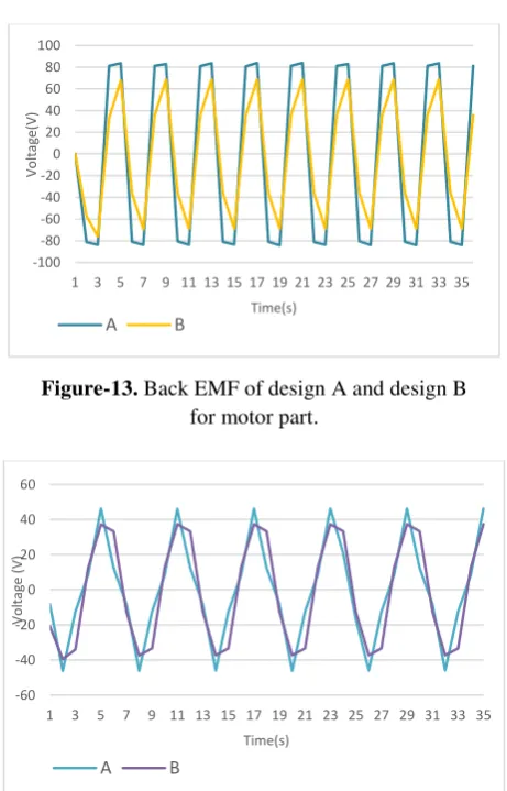
Figure-13. Back EMF of design A and design B
for motor part.
Figure-14. Back EMF of design A and design B for
generator part
From the plotted graph, it is proven that induced voltage is proportional to the flux linkage produced. Based on the performance analysis plotted on figure 14 and 15, it is observed that Design A produced higher induced voltage for both motor and generator compared to Design B. Even though Design B has a reluctant holes to reduce the cogging torque effect of the ceiling fan machine, the induced voltage produced is much lower compared to Design A. Thus, Design A is selected as the best configuration for optimization and fabrication process. -1
-0,5 0 0,5 1
1 3 5 7 9 11 13 15 17 19 21 23 25 27 29 31 33 35
F
lu
x
li
n
k
a
g
e[
W
b
]
Normalize(time)
A B
-0,5 -0,3 -0,1 0,1 0,3 0,5
1 3 5 7 9 11 13 15 17 19 21 23 25 27 29 31 33 35
F
lu
x
li
n
k
a
g
e[
W
b
]
Normalize(time)
A B
-100 -80 -60 -40 -20 0 20 40 60 80 100
1 3 5 7 9 11 13 15 17 19 21 23 25 27 29 31 33 35
Vo
lt
a
g
e(
V)
Time(s)
A B
-60 -40 -20 0 20 40 60
1 3 5 7 9 11 13 15 17 19 21 23 25 27 29 31 33 35
Vo
lt
a
g
e
(V)
Time(s)
[image:8.595.311.542.233.593.2] [image:8.595.57.281.303.459.2] [image:8.595.52.290.531.597.2]The results from the simulation proved that the proposed designs of ceiling fan machine are able to generate electricity.
Table-6. Tabulated value of induced voltage for
design A and design B.
Design A (no notch) B (with notch)
Maximum (V) motor 86.14 68.62 Maximum (V)
generator 47.25 37.15
CONCLUSIONS
A comprehensive literature review was carried out to design the permanent magnet machines of ceiling fan. In this research study, two design models which are Design A and Design B has been proposed. From the simulations, finite element analysis has been performed to justify the proposed design outcome (flux distribution, air gap flux density, flux linkage and induced voltage) using Ansoft Maxwell software. Both proposed design A and B showed good characteristics of flux distribution and both capable in generating additional electricity. However, design A was selected for further optimization and analysis as a result of high induced voltage produced compared to design B. The optimize design will be used to develop a prototype for validating the procedure between the simulation result and experimental result. The output from the completed prototype will be compared with the conventional ceiling fan for performance comparison of output power, efficiency and the speed.
REFERENCES
[1] N. N. Abu Bakar, M. Y. Hassan, H. Abdullah, H. A. Rahman, M. P. Abdullah, F. Hussin, et al., "Identification building energy saving using Energy Efficiency Index approach," in Power and Energy (PECon), IEEE International Conference on, pp. 366-370.
[2] S. Mei-Ju, P. Yuan-Chi, L. Guan-Yu, W. Hung-Yu, and R. Vannithamby, "Performance evaluation for energy-harvesting machine-type communication in LTE-A system," in Vehicular Technology Conference (VTC Spring), IEEE 79th, pp. 1-5.
[3] S. Chalasani and J. M. Conrad, "A survey of energy harvesting sources for embedded systems," in Southeastcon. IEEE, pp. 442-447,.
[4] S. Sudevalayam and P. Kulkarni, "Energy harvesting sensor nodes: survey and implications,"
Communications Surveys & Tutorials, IEEE, vol. 13, pp. 443-461.
[5] M. S. M. Resali and H. Salleh, "Comparison of energy harvesting power management techniques and application," in Electronic Manufacturing Technology Symposium (IEMT), 2010 34th IEEE/CPMT International, pp. 1-5.
[6] L. Junrui and L. Wei-Hsin, "Impedance modeling and analysis for piezoelectric energy harvesting systems," Mechatronics, IEEE/ASME Transactions on, vol. 17, pp. 1145-1157.
[7] Country comparison and historical annual data graph. Available: http://www.indexmundi.com/
[8] J. Carmona-Sanchez, T. I. Asiain-Olivares, G. Rosas-Ortiz, and D. Ruiz-Vega, "Induction motor static models for power flow and voltage stability studies," in Power and Energy Society General Meeting, 2012 IEEE, pp. 1-8.
[9] J.-h. Zhou, C. Chen, X.-w. Zhang, and Y.-a. Chen, "Reducing voltage energy-saving control method of induction motor," in Electrical Machines and Systems (ICEMS), International Conference on, pp. 2159-2162.
[10]N. Shah, N. Sathaye, A. Phadke, and V. Letschert, "Efficiency improvement opportunities for ceiling fans," Energy Efficiency, vol. 8, pp. 37-50, Feb 2015.
[11]C. M. Liu, "Ceiling fan with bi-directional rotation control," ed: Google Patents.
[12]Y. F. Tang, "Ceiling fan with outer-rotor DC brushless motor," ed: Google Patents.
[13]M. Fazil and K. R. Rajagopal, "Development of external rotor single-phase PM BLDC motor based drive for ceiling fan," in Power Electronics, Drives and Energy Systems (PEDES) & 2010 Power India, Joint International Conference on, pp. 1-4.
[15]L. Chuan-Sheng and H. Jonq-Chin, "Development of brushless DC motor with low cogging torque for ceiling fan," in Power Electronics and Drive Systems, 2009. PEDS 2009. International Conference on, pp. 778-782, 2009.
[16]L. Chuan-Sheng, H. Jonq-Chin, and C. Po-Cheng, "Permanent magnet synchronous motor for ceiling fan," in Sustainable Energy Technologies (ICSET), 2010 IEEE International Conference on, pp. 1-4, 2010.
[17]M. A. Afaq, A. Maqsood, K. Parvez, and A. Mushtaq, "Study on the design improvement of an indoor ceiling fan," in Applied Sciences and Technology (IBCAST), 2014 11th International Bhurban Conference on, pp. 279-283, 2014.
[18]K. Sitapati and R. Krishnan, "Performance comparisons of radial and axial field, permanent-magnet, brushless machines," Industry Applications, IEEE Transactions on, vol. 37, pp. 1219-1226, 2001.
[19]A. Cavagnino, M. Lazzari, F. Profumo, and A. Tenconi, "A comparison between the axial flux and the radial flux structures for PM synchronous motors," Industry Applications, IEEE Transactions on, vol. 38, pp. 1517-1524, 2002.
[20]Z. Rahman, "Evaluating radial, axial and transverse flux topologies for 'in-wheel' motor," in Power Electronics in Transportation, 2004, pp. 75-81, 2004.
[21]D. Joo, J.-Y. L. D.-K. Hong and B.-C. W. D.-H. Koo, "High-torque low-speed machines for in-wheel application: comparitive study of radial, axial, and transverse flux machines," in COMPUMAG, Budapest, Hungary 2013.
[22]P. R. Upadhyay and K. R. Rajagopal, "Comparison of performnace of the axial-field and radial-field permanent magnet brushless direct current motors using computer aided design and finite element methods," Journal of applied physics 97, 10Q506 (2005), 2005.
[23]Q. Ronghai, M. Aydin, and T. A. Lipo, "Performance comparison of dual-rotor radial-flux and axial-flux permanent-magnet BLDC machines," in Electric Machines and Drives Conference, 2003. IEMDC'03. IEEE International, pp. 1948-1954 vol.3, 2003.
[24]K. Sitapati and R. Krishnan, "Performance comparisons of radial and axial field, permanent-magnet, brushless machines," Industry Applications, IEEE Transactions on, vol. 37, pp. 1219-1226, 2001.
[25]A. Cavagnino, M. Lazzari, F. Profumo, and A. Tenconi, "A comparison between the axial flux and the radial flux structures for PM synchronous motors," Industry Applications, IEEE Transactions on, vol. 38, pp. 1517-1524, 2002.
[26]A. Parviainen, M. Niemela, J. Pyrhonen, and J. Mantere, "Performance comparison between low-speed axial-flux and radial-flux permanent-magnet machines including mechanical constraints," in Electric Machines and Drives, 2005 IEEE International Conference on, pp. 1695-1702, 2005.
[27]C. Anyuan, R. Nilssen, and A. Nysveen, "Performance Comparisons Among Radial-Flux, Multistage Axial-Flux, and Three-Phase Transverse-Flux PM Machines for Downhole Applications," Industry Applications, IEEE Transactions on, vol. 46, pp. 779-789, 2010.
[28]L. Tae-geun, K. Do-Jin, and H. Jung-Pyo, "Performance improvement by making holes of Interior permanent magnet synchronous motor," in Electrical Machines and Systems, 2009. ICEMS 2009. International Conference on, pp. 1-4, 2009.
[29]W. Jian, W. Shiyu, Z. Dongsheng, and X. Jie, "Influence of pole-arc width on cogging torque in permanent magnet motors," in Mechatronics and Automation (ICMA), 2012 International Conference on, pp. 1591-1596, 2012.
[30]L. Dosiek and P. Pillay, "Cogging torque reduction in permanent Magnet Machines," Industry Applications, IEEE Transactions on, vol. 43, pp. 1565-1571, 2007.
[31]J. Guandong and C. D. Rahn, "Field weakening for radial force reduction in brushless permanent-magnet DC motors," Magnetics, IEEE Transactions on, vol. 40, pp. 3286-3292, 2004.