2019 International Conference on Artificial Intelligence, Control and Automation Engineering (AICAE 2019) ISBN: 978-1-60595-643-5
The Design and Implementation of Notch Filter
Based on Least Mean Square
Shuo-yu ZHANG
*School of Information and Software Engineering, University of Electronic Science and Technology of China, Chengdu China
*Corresponding author
Keywords: Notch Filter, Least Mean Square, Single Chip Computer.
Abstract. Data acquisition and analysis system often encounters interference of single frequency or narrowband signal in work. For example, in power frequency environment, 50Hz interference signal often affects the normal operation of the system and affects the effect of data acquisition and analysis. For narrowband or single frequency noise, the best denoising method is notch filter. This paper describes the design of notch filter based on least mean square (LMS) algorithm and its implementation based on single chip computer platform. The simulation and experimental results show that this method achieves good results in filtering effect and system computing speed.
Introduction
Single frequency or narrowband noise is a common interference in data acquisition and analysis system. For example, in power frequency environment, 50Hz interference signal often affects the normal operation of the system and the effect of data acquisition and analysis. For narrowband or single frequency noise, the best denoising method is notch filter. The adaptive notch filter can track the change of interference, and its stopband is very narrow in frequency, which is very close to the ideal characteristic. LMS algorithm plays an important role in adaptive algorithm [1, 2, 3]. It is simple, computational and easy to implement. We designed an adaptive notch filter based on the least mean square algorithm and simulated the filtering effect. The filter is implemented on 51 single chip computer platform. The system is tested and the filtering effect and calculation speed are good.
Typical Application of Notch Filter in Signal Acquisition Application System
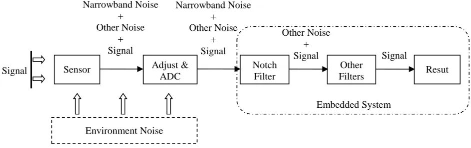
[image:1.595.66.538.559.708.2]The typical application of notch filter in signal acquisition application system is shown as Fig.1.
Figure 1. Typical application of notch filter in signal acquisition application system.
In many application scenarios, single-frequency or narrowband interference is the main noise, and the noise energy is very high, even far higher than the signal energy. After sensor acquisition, signal adjustment and analog-to-digital conversion, the system acquires the mixed signal of single-frequency or narrowband noise, other noise and useful signal. For single-frequency or
Sensor Adjust & ADC
Notch Filter
Other
Filters Resut
Signal Environment Noise Embedded System Narrowband Noise + Other Noise + Signal Narrowband Noise + Other Noise + Signal Other Noise +
narrowband noise, notch filter is the best choice. After filtering by notch filter, the main noise is canceled. Then other filters are used to cancel other noises. Finally, useful signals are obtained for result analysis.
Principle and Design of Adaptive Notch Filter
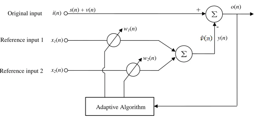
[image:2.595.101.516.167.360.2]The principle of the adaptive notch filter is shown in Fig. 2.
Figure 2. Principle of adaptive notch filter.
The principle and design method of adaptive notch filter have been extensively studied [4]. The original input is a mixed signal of effective signal and single-frequency noise. It can be expressed as
𝑑(𝑛) = 𝑠(𝑛) + 𝑣(𝑛) (1)
𝑠(𝑛) is the effective signal, and the single-frequency noise
v(n) = Acos(ωn + θ)) (2) In the expression, A is the amplitude of noise. 𝜔 is the frequency and 𝜃 is the phase.
Reference input 1 can be expressed as
𝑥1(𝑛) = 𝐵𝑐𝑜𝑠(𝜔𝑛 + 𝜑) (3) Reference input 2 can be expressed as
𝑥2(𝑛) = 𝐵𝑠𝑖𝑛(𝜔𝑛 + 𝜑) (4) The output y of x1 and x2 is obtained by linear combiner with weights of w 1 and w2. The linear
output y can be expressed as
𝑦(𝑛) = 𝑤1𝑥1(𝑛) + 𝑤2𝑥2(𝑛) (5) Then
𝑦(𝑛) = 𝑤1𝐵𝑐𝑜𝑠(𝜔𝑛 + 𝜑) + 𝑤2𝐵𝑠𝑖𝑛(𝜔𝑛 + 𝜑) (6) The system adjusts the weights w1 and w2 by adaptive algorithm to reach the optimum values 𝑤1∗ and 𝑤2∗, then
𝑦(𝑛) = 𝑤1∗𝐵𝑐𝑜𝑠(𝜔𝑛 + 𝜑) + 𝑤
2∗𝐵𝑠𝑖𝑛(𝜔𝑛 + 𝜑) (7) Then
i(n)
x1(n)
Σ
x2(n)
Σ
y(n) +
-o(n)
w1(n)
w2(n)
Original input
Reference input 1
Reference input 2
s(n) + v(n)
𝑜(𝑛) = 𝑑(𝑛) − 𝑣̂(𝑛) = 𝑠(𝑛) + 𝑣(𝑛) − 𝑣̂(𝑛) (9)
o(n) is the best approximation of effective signal s(n). 𝑠(𝑛) ≈ 𝑜(𝑛) (10)
The system gets the best estimate of single-frequency noise 𝑣(𝑛) by adjusting the weights w1 and w2 through adaptive algorithm. We chose LMS as the adaptive algorithm. The rule is minimum mean square error, minimum of 𝐸[(𝑣(𝑛) − 𝑣̂(𝑛))2]. The mean square error of 𝑜(𝑛) is expressed as 𝐸[𝑜2(𝑛)] = 𝐸[(𝑠(𝑛) + 𝑣(𝑛) − 𝑣̂(𝑛))2] (11)
𝑠(𝑛) and 𝑣(𝑛) are not related, so it’s easy to prove that let 𝐸[𝑜2(𝑛)] be minimum equals to let 𝐸[(𝑣(𝑛) − 𝑣̂(𝑛))2 be minimum. By iteratively adjusting weights w1 and w2, 𝐸[𝑜2(𝑛)] is minimized. The weight iteration formula of LMS is 𝑤(𝑛 + 1) = 𝑤(𝑛) + 2𝜇𝑜(𝑛)𝑥(𝑛) (12)
In the formula, μ is the convergence factor of the adaptive filter. The weights of the next moment can be obtained from the weights of the current moment plus the input vectors with the system deviation function as the proportional factor. The design of the notch filter based on LMS the filter can be represented by the following set of formulas. Let the initial weights 𝑤1(0) and 𝑤2(0) be 0. We set μ to the right value. The larger 𝜇 value converges faster and the smaller 𝜇 value has higher accuracy. 𝑤1(0) = 0, 𝑤2(0) = 0, 𝜇 = 𝑅𝑖𝑔ℎ𝑡 𝑉𝑎𝑙𝑢𝑒 (13)
𝑜(𝑛) = 𝑑(𝑛) − [𝑤1(𝑛)𝐵𝑐𝑜𝑠(𝜔𝑛 + 𝜑) + 𝑤2(𝑛)𝐵𝑠𝑖𝑛(𝜔𝑛 + 𝜑) ] (14)
𝑤1(𝑛 + 1) = 𝑤1(𝑛) + 2𝜇𝑜(𝑛)𝑥1(𝑛) (15)
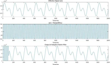
Figure 3. Simulation result of the adaptive notch filter.
Implication of the Adaptive Notch Filter Based on Single Chip Computer
Figure 4. Program flow chart of the adaptive notch filter.
Conclusion
This paper describes the application, principle and design of LMS notch filter and its implementation based on single chip computer. The simulation results show that the filter can effectively eliminate single-frequency noise at very low signal-to-noise ratio. In the future research, we will realize the intelligent assignment of convergence factor μ.
References
[1] Zhuangyao T, Bilal A. A New LMS Algorithm Based Dead-time Compensation Method for PMSM FOC Drives[J]. IEEE Transactions on Industry Applications, 2018:1-1.
[2] Batabyal T, Weller D S, Acton S T. PrecoG: an efficient unitary split preconditioner for the transform-domain LMS filter via graph Laplacian regularization[J]. 2018.
[3] Bujjibabu P, Sirisha K. Design and implementation of efficient IIR LMS adaptive filter with improved performance[C]// International Conference on Big Data Analytics & Computational Intelligence. 2017.
[4] Zhengzhou Li, Matlab digital signal processing and its application, Beijing: Tsinghua University Press, 2008.
[5] Information on http://www.stcmicro.com/datasheet/STC15W4K32S4-en.pdf.
Begin
Initialize parameter w1 (0)=0, w2(0)=0, n=0
Estimate right value of factor μ
o(n)=d(n) - [w1(n)*x1(n)+ w2(n)*x2(n)]
w1(n+1)= w1(n)+2μo(n) x1(n) w2(n+1)= w2(n)+2μo(n) x2(n)
Loop is over
End N