programming manual
VT-15
GRAPHICS SOFTWARE SYSTEM
PROGRAMMING MANUAL
Copyright
@
First Printin9, November
1970Second Printing, October
19711971
by Digital Equipment Corporation
The information presented in this manual
is for informational purposes only and is
subject to change without notice.
The following are trademarks of Digital Equipment
Corporation, Maynard,
~assachusetts.DEC
DIGITAL
PREFACE
This manual describes the software provided for the VT15 Graphics
Display Processor and its optional:
a} VL~4 Light Pen,
b) LK35 Keyboard, and,
c) VW~lBP Writing Tablet and Control.
The information provided is applicable for users employing either the
Disk Operating System (DOS) or Advanced Monitor Software System (ADSS).
It was assumed in the preparatiqn of this manual that the user was
familiar with the contents of the software manual describing the
operating system (DOS or ADSS) being used. A list of applicable manuals
REFERENCE MANUALS
The user should be familiar with the following DEC documents.
PDP-IS/20/30/40 ADVANCED Mon.itor Software System - ADVANCED Monitor
System description. (DEC-IS-MRZA-D)
UTILITY PROGRAMS MANUAL - Utility programs common to PDP-15 Monitor
Systems. (DEC-15-YWZA-D)
MACRO-15 - MACRO assembly language for the PDP-15. (DEC-15-AMZA-D)
FORTRAN IV - PDP-IS version of the FORTRAN IV compil,er language.
(DEC-15-KFZA-D)
GRAPHIC-IS REFERENCE MANUAL - This Reference Manual describes the
basic Graphic 15 processor and its interfacing arrangement with the
PDP-15 computer. The information in this manual is intended to provide
the Graphic 15 user with the knowledge necessary for programming at
the machine-language level, to familiarize him with the operation of
the basic Graphic 15 system, and to provide a brief description of
the programming philosophy and principles of operation. (DEC-15-GWSA-D)
2.1 2.2 2.3 2.4 2.5 2.6 2.7 2.8 2.9 2.10 3.1 3.2 3.3 3.4 3.4.1 3.4.2 3.4.3 3.4.4 3.5 3.6 3.7 4.1 4.2 5.1 CONTENTS
CHAPTER 1
INTRODUCTION
CHAPTER 2
SUBPICTURE ROUTINES
General Restrictions
LINE Subroutine
TEXT Subroutine
COpy Subroutine PRAMTR Subroutine
GRAPH Subroutine
BLANK Subroutine
UNBLNK Subroutine
CIRCLE Subroutine
ROTATE Subroutine
CHAPTER 3
MAIN DISPLAY FILE ROUTINES
DINIT (Display Initialize) Subroutine
DCLOSE (Display Terminate) Subroutine
SETPT (Set Point) Subroutine
PLOT Subroutine
PLOT A Subpicture (COPY)
PLOT a Line (LINE)
PLOT a Control Command (PRAMTR)
PLOT a Text String (TEXT)
DELETE Function
REPLOT Function
RSETPT Function
LTORPB Function
TRACK Subroutine
DYSET Subroutine
CHAPTER 4
INPUT ROUTINES
CHAPTER 5
RELOCATING ROUTINES
Page 1-1 & 1-2
5.2 6.1 6.2 6.3 6.4 6.5 6.6 6.7 6.8 7.1 7.2 7.3 7.4 7.5 7.6 7.7 7.8 7.9 8.1 8.2 8.3 8.4 8.5 8.6 8.7 9.1 9.1.1 9.1.2
DYLINK Subroutine
CHAPTER 6
SYSTEM I/O DEVICE HANDLER
.INIT (Initialize) Macro
.READ Macro
.WRITE Macro
.WAIT Macro
.WAITR Macro
.CLOSE Macro
.FSTAT Macro
Ignored Functions
CHAPTER
7-LK35 KEYBOARD HANDLER
.INIT (Initialize) Macro
.READ Macro
.WAIT Macro
.WAITR Macro
.CLOSE Macro
.FSTAT Macro
Ignored Functions
Illegal Functions
Legal Control Characters
CHAPTER 8
vwo
1 WRI~~ING TABLET HANDLER.INIT (Initialize) Macro
.READ Macro
.WAIT Macro
.WAITR Macro
.FSTAT Macro
.CLOSE Macro
Ignored Functions
CHAPTER 9
TEXT DISPLAY/EDIT FUNCTIONS
EDITVT
Setup Commands
9.1.3. 9.2. 9.2.1. 9.2.2. 9.2.3.
Display Modes CONTROL X FEATURE SCROLL Mode
PAGE Mode
TV ON/OFF Monitor Command HALF ON/OFF Monitor Command 9.2.4.
9.2.5. Differences Between CTRL X In V5A And In DOS
APPENDIXES
A. Mnemonics Commonly Used in Graphics Subprogram Calls
B. Display Instruction Groups Generated by Graphics Subprogram Calls
C. Macro Expansion of Graphics Subprogram Calls
D. Conditional Assembly of Graphics Subprograms
Figure 2-1 Figure 2-2 Figure 2-4
Figure 4-1
]:t'igure
4-2
Figure 5-1
Table 2.1 Table 4.1
ILLUSTRATIONS
Subpicture File Containg Four Vector Sine Wave Program Example
Operation of BLANK/UNBLNK Subroutine
TRACK Program (FORTRAN Example)
TRACK Program
(MACRO15
Example)
DYSET/DYLINK Program Example
TABLES Display Parameter Settings
Description of CALL TRACK Arguments
Commands
CHAPTER 1
INTRODUCTION
This manual presents a detailed description of the PDP-lS/VTlS Graphics
Sub-program Package and is primarily concerned with those display subroutines and
calling user programs used to exhibit information and communicate with the
computer. The Graphics subprograms generate display commands that allow the
user to define display elements and direct the linking, displaying, and
delet-ing of those elements. Their primary purpose is to provide a simplified means
of using the VTlS Graphic Display device without requiring detailed
familiar-ity with the hardware.
In this manual, Graphic Routines are described in detail as follows:
Chapter 2.
3.
4.
S.
6.
7.
8.9 •
Subpicture Routines
Main Display File Routines
Input Routines
Relocating Routines
System I/O Device Handler
LK3S Keyboard Handler (LKA)
VWOl Writing Tablet Handler (VWA)
Text Display/Edit Functions
Subprograms which consist of Graphic Routines mentioned above are called by
user programs written in MACRO or FORTRAN IV language. The depth of coverage
of these routines is intended to provide a very basic understanding of the
use of the VTlS Graphic Display system. Much useful information may be found
in appendices following Chapter 6.
The PDP-IS is designed with an autonomous systems structure and the VTlS
fol-lows this same philosophy; i t operates asynchronously from the basic processor.
Features include a cycle time of 7S0 nanoseconds, a character generator (with
64 printing characters and 4 control characters), a hardware program counter, a
fast vector capability (1/4 inch in 1 usec) , and a wide range of hardware options.
The VTlS Graphics Software is designed for a minimum hardware configuration, as
follows:
PDP-IS with KSR-33
8K Core Memory (12K required for Text Editor)
Paper Tape High-Speed Reader/Punch
VTlS Display Processor
VT~4 Display Console
The Graphics Software consists of a group of routines that can be called by user
programs. Calls to these rout:ines build display files in a portion of PDP-IS
memory that has been allocated by the calling program for such a purpose. The
display files contain instructions and data upon which the VTlS Processor
operates and to which its digital control and analog outputting circuits
re-spond. The VTlS Processor has a set of 12 basic machine-language in$tructions
which give i t excellent versatility in the display of points, basic vectors,
graphic plots, and ASCII characters. The commands contained in a main display
file link together individual subpicture files causing the desired image to he
displayed. Calls to other routines control the flow of the program upon the
occurrence of light pen or push button interrupt. In this way, program paths
can be enabled to modify the sequence of display commands and therefore modify
the picture.
The VTlS Graphics Software is designed to run in Bank/Page Mode and to be usee
with either FORTRAN IV or MACRO-IS programs. FORTRAN IV programs devised by
the user will consist of standard FORTRAN IV statements. and calls to routines
within the VTlS Graphics package. Other than system software normally used
for compilations, assemblies, loading, etc., the VTlS Graphics software does
not require use of any other programs.
The following manuals contain information useful in understanding and
DOS Users
a) DOS Users Manual
ADSS Users
a. ADVANCED Monitor Software System for PDP-lS/20/30/40 Systems
Common Manuals
a} MACROlS, Macro-Assembler Program
b) FORTRAN IV Programmer Reference Manual (8K Systems)
c) Utility Program Manuals
d) FORTRAN IV Language Manual (16K Systems)
e) FORTRAN IV Operating Environment (16K Systems)
Hardware Manuals
a} Graphic-IS Reference Manual
b) VWOl Writing Tablet, Vol. 1
DEC-lS-MRDA-D
DEC-lS-MRZB-D
DEC-lS-AMZC-D
DEC-lS-KFZB-D
DEC-lS-YWZB-D
DEC-lS-GFWA-D
DEC-lS-GWSA-D
DEC-OO-H4AA-D
The GRAPHIC-IS Reference Manual is of particular importance to the
VTlS programmer. This manual describes the basic Graphic IS processor
and its interfacing arrangement with the PDP-IS computer. The
informa-tion in this manual provides the user with the data needed for machine
level programming and familiarizes the user with the operation of the
CHAPTER 2
SUBPIC~URE ROUTINES
These routines allow the user to incorporate point plotting, line drawing, and
text display in his programs with minimum effort. Calls to these routines
together with standard FORTRAN or MACRO statements build self-contained
sub-picture display files with executable display instructions. Each subpicture
file contains all the display instructions needed to generate a specific image on
the VT~4 Display console. These files are accessed by a Main Display File
(described in Chapter 3) in any order or sequence during the execution of the
display program. Most Subpicture Routines will normally be called prior to
initiating execution of a
Main
Display File, thus building a library of accessiblegraphics (i.e., complete or partial pictorial images) from which complex images
may be formed. The subpicture display routines and their functions are:
LINE - Draws a line (intensified) or moves the beam (not intensified)
from current position.
option, if available.}
(Provides for using random vector
TEXT - Displays strings of 5/7 ASCII text previously defined by
the user in dimensioned arrays.
COpy - Links subpicture files (similar to subroutining) to form a
composite display image. Provides for using hardware
SAVE/RESTORE feature, if desired.
PRAMTR - Sets scale, intensity, light pen sensitivity, blink, etc.,
for this subpicture, or some portion thereof.
GRAPH - Displays specified data points in graph form.
BLANK - Inhibits display of any copy of this subpicture.
UNBLNK - Reverses the action of the BLANK subroutines.
All display file storage is supplied by the FORTRAN user in the form of
dimen-sioned integer arrays; MACRO-15 users must also allocate display file storage in
some appropriate manner. To facilitate storage management, the first location
of each file contains the length of the file. Limited reuse of storage is
provided for in the Main Display File routines.
The first location of a subpicture file (PNAME) contains its current length
-this value must be set to zero when the first reference to the sUbpicture display
file is made. After the first reference, the contents of PNAME is set equal to
the length of the subpicture file; this value is updated by any subsequent calls
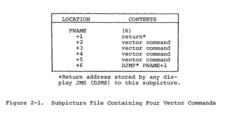
LOCATION
PNAME +1 +2 +3 +4 +5 +6
CONTENTS
(6)
return*
vector command vector command vector command vector command DJMP* PNAME+l
*Return address stored by any dis-play JMS (DJMS) to this subpicture.
Figure 2-1. Subpicture File Containing Four vector Commands
Since display files are generated and stored in arrays dimensioned by the user,
they are fully accessible to the user and can be written out or read in using
FORTRAN unformatted I/O statements.
Storage overhead for each subpicture display file is three words; the first word
contains the file length, the second is used for a return address, and the third
(last in file) contains the VT15 display command DJMP* PNAME+l.
The procedure for generating a subpicture file such as that illustrated in
Figure 2-1 requires some further explanation. The four calls to subroutine LINE,
shown below, will result in such a file. This subpicture file will simply draw
a square when accessed by the Main Display File or another subpicture file.
DIMENSION IPNAME(l~) IPNAME(l)=~
CALL LINE (l~~,~,l,IPNAME(l»
CALL LINE (~,l~~,l)
CALL LINE (-l~~,~,l)
CALL LINE (~,-l~~,l)
Note in the above example that storage allocation for the subpicture file was
provided by the DIMENSION statement. Also, the first location, IPNAME(l) , was
set to zero before the first reference to i t , thus indicating a new file. The
identity of a subpicture file is the address of its first location (PNAME)and is
given or implied, as an argument in all calls 'to subpictu:re routines. Each
[image:15.615.123.517.76.294.2] [image:15.615.125.481.491.617.2]while being displayed.
Limited reuse of storage is provided for in the main display file routines RSETPT,
REPLOT, and DELETE which are explained in Chapter 3. In this chapter, the number
of locations required for display instructions generated by each subroutine call
is indicated in each of the subroutine descriptions. Naturally, the total number
of locations that can be allocated for display files is limited by the amount of
core memory available.
2.1 GENERAL RESTRICTIONS
The following general restrictions apply to all subpicture routines except BLANK
and UNBLNK.
a. All arguments (constants or variables) must be of integer form.
b. The variable PNAME must be set equal to zero before the first call referencing it.
c. Sufficient space must follow PNAME to contain the subpicture file.
2.2 LINE SUBROUTINE
The LINE subroutine adds to the specified subpicture file the commands necessary
to draw a line (beam intensified) or move the beam (not intensified) through a
specified displacement from the current beam position.
The call statement has the form:
CALL LINE (DELTAX,DELTAY,INT[,PNAME])
where the enclosing brackets [ ] indicate an optional argument.
DELTAX represents the horizontal component of beam displacement in raster units
and DELTAY represents the vertical component. The integer variable INT indicates
whether the line is to be intensified (INT=l, the line will be visible; INT=~
the line will not be visible). The variable PNAME represents the first location
of this subpicture display file and is the name by which the subpicture is referred
to in later manipulation. For example, if a subpicture is to start in the
dimensioned array ILEMNT, the form is:
CALL LINE(DELTAX,DELTAY,INT,ILEMNT(l»
Subroutine LINE adds one command to the display file if DELTAX and DELTAY define
one of the eight basic directions:
VN!INCR (where VN is vector direction n, and INCR is units)
If DELTAX and DELTAY do not define one of the eight basic directions, LINE tests
for availability of the random vector option, and, if available, adds two
commands to the display file:
SVX!DELTAX (stroke vector, x displacement)
SVY!DELTAY (stroke vector, y displacement)
If not one of the eight basic directions, and if the random vector option is not
available, LINE approximates the required line with a series of basic vectors.
The number of commands added to the display file is added to the contents of
location PNAME.
In addition to the general restrictions (paragraph 2.1) outlined previously for
subpicture routines, there is another restriction that should be considered when
using subroutine LINE: DELTAX and DELTAY should always bE~ signed integers with
magnitudes not exceeding 1~23.
of the LINE subroutine.
The following two statemE~nts illustrate the use
CALL LINE (~,6~,1,ILINE(1»
This statement generates a display instruction to draw a vertical line 69
raster units long. The display instruction (a basic vector) is stored at the end
of subpicture file ILINE.
I
69
.~<_J~
___
Starting pointThe following statement illustrates use of the LINE routine to draw a sloped line:
CALL LINE(IDX,IDY,l,ILINE(l»
where IDX=-3~9 and IDY=299 , we obtain the following:
Y
Starting point
Note that the random vector option is assumed to be available (otherwise, such
2.3 TEXT SUBROUTINE
The TEXT subroutine adds to the specified subpicture file commands necessary to
display an identified text string - starting at the current beam position. The
standard text font is drawn on a l~ by 14 dot matrix. Each character causes an
increment of 14 raster units to the X position of the beam. The form is:
CALL TEXT(STR,N[,PNAME]}
The input variable STR identifies the dimensioned real array that contains the
string of characters to be displayed in lOPS ASCII (Hollerith) form - five 7-bit
characters packed in two words. The variable, N, is an integer variable that
indicates the number of characters to be displayed in the referenced array. If
N~~,
an ALT MODE will be inserted after the nth character to allow escape from the character mode. If N=~, ALT MODE will not be inserted in the TEXT array.The variable PNAME is the first location of this subpicture file, as in the call
to LINE.
The TEXT subroutine adds three locations to the assembled display file; three is
added to the contents of PNAME.
CHARS
*
.+2DJMP .+2
(FULL IS-BIT ADDRESS)
NOTE
If 5/7 ASCII data is loaded into the array from an external source (as opposed to being defined in a FORTRAN DATA statement), i t may contain certain non-printing characters (such as carriage return, line feed, etc.) that must be allowed for when specifying the argument N.
In addition to the general restrictions outlined in paragraph 2.1, the array
referred to by TEXT must be of sufficient size to accommodate the escape
char-acter that will be inserted by TEXT. Also, to ensure that the display processor
is conditioned to escape on ALT MODE, i t is necessary to start up an empty
Main File with a call to DINIT (described in Chapter 3). When this is done, a
display parameter word is inserted in the new Main File to enable escape on
ALT MODE only. (The alternative is to escape on carriage return or ALT MODE,
whichever comes first; however, this option is not selectable using Main File or
subpicture routines.)
The following example illustrates the manner in which TEXT to be displayed is
Setup to display "15 ASSABET RD.II is
DIMENSION ADDR(4)
DATA ADDR(l)/SHlS AS/,ADDR(2)/SHSABET/,ADDR(3)/4H RD./
The call statement to display the TEXT from subpicture IPIC is:
CALL TEXT (ADDR(l) ,14,IPIC(l»
2.4 COPY SUBROUTINE
The COpy subroutine enables two or more subpicture display files to be linked
together to generate a composite display image. This is accomplished by a
display subroutining technique. COpy adds to one subpicture display file the
commands necessary to call a second subpicture. The second subpicture begins at
the last beam position specified by the first subpicture. The form is:
CALL COPY(RST,PNAMEl[,PNAME])
The variable, RST, indicates whether to save and restore display parametersl
when copying the specified subpicture. RST may be set to ~ or 1; ~ indicates
no SAVE/RESTORE option and 1 indicates SAVE/RESTORE option is to be used. The
variable PNAMEI is the first location of the subpicture to be copied. PNAME is
the first location of the subpicture file to which display instructions generated
by this call are to be added.
The COpy subroutine adds three locations to the display file when the
SAVE/RESTORE option is not specified. These three locatio:ns are as follows:
DJMS* .+2
DJMP .+2
(ADDRESS of PNAMEl+l)
However, when SAVE/RESTORE is specified, COpy adds six locations to the display
file as follows:
SAVE .+4
DJMS* .+2
DJMP .+3
(ADDRESS of PNAMEl+l) (STATUS)
RSTR .-1
lThese parameters include (but are not limited to) scale, intensity, blink, offset, and rotate, which can be set by calling subroutine PRAMTR (see paragraph 2.5.1)
where the SAVE instruction stores the effected display parameter settings in the
STATUS word before executing the normal sequence of COpy commands. Upon
return-ing from the subpicture, these parameters are restored to their original settreturn-ings
by the RSTR instruction. The contents of PNAME is increased by three or six, as
required.
In addition to the general restrictions outlined in paragraph 2.1, PNAME 1 need
not be defined when COpy is called but must be a defined subpicture when PNAME is
displayed. The following statement:
CALL COPy(~,WINDOW(l) ,HOUSE(l»
adds a call to the window subpicture file to the file identified as HOUSE. Note
that the SAVE/RESTORE option was not specified.
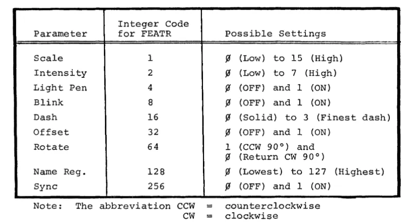
2.5 PRAMTR SUBROUTINE
The PRAMTR subroutine allows the user to add to the specified subpicture file the
commands necessary to set up the following display features. (See DEC, Graphic-15
Reference Manual, PDP-15, for more detailed information.)
Scale setting - Setting the scale has a different effect, depending on where i t
is used. If used when plotting characters or vectors, i t specifies the number of
times (~ - 15) that the unscaled vector (or stroke of a character) is to be
re-pea~ed. If used in conjunction with the graph subroutine, the scale specifies
the coordinate distance between given points.
Intensity Setting - The brightness of the display can be controlled in eight
in-cremental steps between maximum dark and maximum light by specifying an integer
variable or constant to represent the wanted brightness, between ~ and 7.
Light Pen Sensitivity - The ability of the light pen to sense a "hit" can be
controlled by means of this feature.
Blink Setting - Use of this feature enables blinking of some portion or all of the
displayed image. This feature causes characters as well as vectors to blink at a
rate of approximately four times a second.
Dash Setting - This feature enables drawing of dashed lines and can be set
from ~ to 3 as follows:
Setting
~ 1
2 3
Illuminated Raster Points
ALL ON 3 ON 1 OFF 4 ON 2 OFF 4 ON 4 OFF
Offset Setting - Since the VT15 display processor defines a square drawing area,
use of this area by means of the offset feature. When the offset is enabled, the
absolute origin is relocated to the lower right-hand corner of the normal display
area. This small area (approximately 9-1/2 x 1-1/2 in.) can be used for light
buttons, special figures, etc., ~Nithout disturbing the normal graphics area.
Rotate Setting - This feature allows the displayed image to be rotated 9~ degrees
in the counterclockwise direction or returned to its normal orientation i f i t is
currently rotated. This could bE~ useful for labeling graphs on the vertical axis
or for any of a number of other applications.
Name Register Setting - The ability to set the Name Register is required to
iden-tify the location of light pen hits when using subroutine LTORPB. However, i t is
a feature which, when used at the programmer's discretion, can be helpful in
many other applications. Once set, i t retains its value until set to a different
value.
Sync Feature - This feature can be used to avoid phospher burnout when displaying
files that require 32 milliseconds or less for execution. The display will halt
and remain stopped until a sync pulse, derived from the local power main, enables
execution to resume. This essentially locks execution of the display file to the
power line frequency, which eliminates a visible swimming effect on the CRT.
By using the PRAMTR call statement, more than one feature (each with its
corres-ponding settings) may be specified, using the following 1:echnique:
1. Add together the integer code numbers that identify the selected
features and assign this value to the variable FEATR. For example:
For scale (1) and Intensity (2), FEATR will have the value 3.
2. List the desired settings, as arguments, in ascending order
accord-ing to the values of the numeric assigned to thei.r correspondaccord-ing
features (the argument list 3,2,6 would specify a value of 2 for
scale (feature 1) and of 6 for Intensity (feature! 2». The general
call statement form is:
(a) One feature - CALL PRAMTR(FEATR,VALUE[,PNAME:])
(b) More than one feature and setting
-CALL PRAMTR(FEATR(S),VALUEI,VALUE2 ••. [,PNAME])
The variable FEATR represents the display feature being set. The variable
VALUE is the value to which FEATR is set. (See Table 2.1 for FEATR and VALUE
settings.) PNAME is the first location of this subpicture file.
depend-ing on the type of argument l i s t used. l The number of commands added to the file is added to the contents of location PNAME.
Table 2.1 Display Paran~eter Settings
Integer Code Parameter for FEATR
Scale 1
Intensity 2
Light Pen 4
Blink 8
Dash 16
Offset 32
Rotate 64
Name Reg. 128
Sync 256
Note: The abbreviation CCW CW
Possible Settings
~ (Low) to 15 (High)
~ (Low) to 7 (High)
~ (OFF) and 1 (ON)
~ (OFF) and 1 (ON)
~ (Solid) to 3 (Finest dash)
~ (OFF) and 1 (ON) 1 (CCW 900
) and
~ (Return CW 900 )
~ (Lowest) to 127 (Highest)
~ (OFF) and 1 (ON)
counterclockwise clockwise
In addition to the general restrictions, the PRAMTR subroutine must be used with
care, since the setting given is in effect until explicitly changed. Thus, i f
the blink is turned on at the beginning of a subpicture, i t must be turned off
at the end, otherwise the entire display image will blink (unless, of course, the
SAVE/RESTORE option is used in calls to this subpicture).
The following single feature statement:
CALL PRAMTR (2,7,HOUSE(1»
specifies an intensity level of 7, for the subpicture display file starting at the
first location of array HOUSE. The following multiple-feature statement:
CALL PRAMTR (SCALE+INT+LPEN,~,4,1,IN(1»
specifies the values ~ and 4 for scale and intensity, and turns on the light pen sensitivity. Appropriate display commands are added to the file that begins with
[image:22.622.132.545.140.370.2]the first location of array IN.
2.6 GRAPH SUBROUTINE
The GRAPH subroutine adds to the specified subpicture file the commands
necessary to display in graph form the identified set of data points. One
coordinate is sequentially set to the value of each data point, the other
coordinate is then automatically incremented (in the current scale), leaving
the beam positioned one increment past the end of the graph. Note that axes
and labeling must be provided separately. The call statement form is:
CALL GRAPH (DTA, N,A [", PNAME] )
DTA represents an INTEGER array that contains the set of data points, one per
word, in the range ~ to 1~23. The variable N indicates the number of data
points to be displayed. The variable A indicates which axis to increment, where
A is set to either ~ or 1. (A=~ specifies incrementing the X axis and setting Y to data values; A=l specifies incrementing the Y axis and setting X to data
values.) The variable PNAME specifies the first location of the subpicture
file to which the generated display commands are to be adde:d.
The GRAPH subroutine adds to the subpicture file a number clf graph-plot commands
equal to the number of entries in the data set, as shown be:low. The number of
commands added to the file is added to the contents of PNAM.E.
GX!VALI GX!VAL2
GX!VALn or
GYIVALI GYIVAL2
GYIVALn
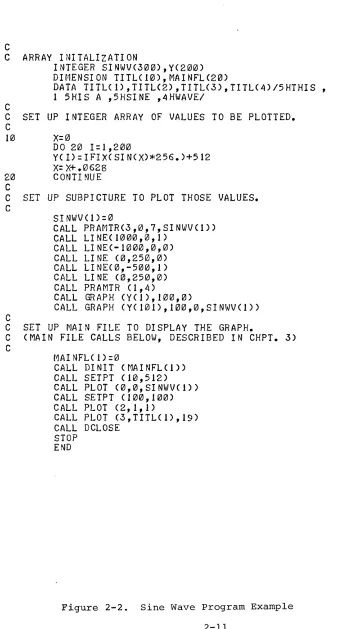
One way to summarize the discussion up to this point is to review a program}
(Figure 2-2 Sine Wave Program Example) Which illustrates the use of GRAPH and
other subroutines.
2.7 BLANK SUBROUTINE
The BLANK subroutine is used to prevent the displaying of any copy of the
specified subpicture. However, the display file length is not changed. The form
is:
CALL BLANK (PNAME)
C
C ARRAY INITALIZATION
C
INTEGER SINWV(300),Y(200)
DIMENSION TITL(10),MAINFLC20)
DATA TITL(1),TITLC2),TITLC3),TITL(4)/5HTHIS ,
1 5HIS A ,5HSINE ,4HWAVEI
C SET UP INTEGER ARRAY OF VALUES TO BE PLOTTED.
C
10
X=0
DO 20 1=1,200
YCI)=IFIXCSIN(X)*256.)+512
X=X+.0628
20
CONTINUE
C
C SET UP SUBPICTURE TO PLOT THOSE VALUES.
CSINWVCl)=0
CALL PRAMTRC3,0,7,SINWV(I»
CALL LINE(1000,0,1)
CALL LINEC-1000,0,0)
CALL LINE (O,250,O)
CALL LINEC0,-500,1)
CALL LINE C0,250,0)
CALL PRAMTR Cl,4)
CALL GRAPH CY(1),100,0)
CALL GRAPH (YCI01),100,0,SINWV(I»
C
C SET UP MAIN FILE TO DISPLAY THE GRAPH.
C (MAIN FILE CALLS BELOW, DESCRIBED IN CHPT. 3)
C
MAINFL(1)=0
CALL DINIT (MAINFL(I»
CALL SETPT CI0,512)
CALL PLOT (0,0,SINWVC1»
CALL SETPT (100,100)
CALL PLOT (2,1,1)
CALL PLOT (3,TITL(1),19)
CALL DCLOSE
STOP
END
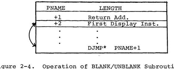
[image:24.612.92.438.102.731.2]PNAME LENGTH
+1 Return Add.
~ +2 First Display Inst.
(
·
·
·
·
·
DJMP*·
PNAME+lFigure 2-4. Operation of BLANK/UNBLANK Subroutine
In figure 2-4 the command in location PNAME+2 (the first executable command in
the subpicture file) is interchanged with the DJMP* PNAME+l located at the end of
the subpicture file. PNAME must be a defined subpicture file (BLANK has no
mean-ing as the first call referrmean-ing to PNAME). The subpicture files should not be
modified while BLANKed. The following example would prevent the subpicture
dis-play file starting at the first location of array IPIC from being disdis-played.
CALL BLANK (IPIC(l»
2.8 UNBLNK SUBROUTINE
The UNBLNK subroutine reverses thE~ action of the BLANK subroutine, allowing a
previously BLANKed subpicture to be displayed. The form is,
CALL UNBLNK (PNAME)
where the variable PNAME is the subpicture to be UNBLNKed. The command in the
last location of the subpicture file (placed there by a call to BLANK) is
inter-changed with the DJMP* in location PNAME+2. If the referenced subpicture is not
already BLANKed, UNBLNK will return without changing the file.
The following statement will enable the previously BLANKed subpicture IPIC to
be displayed.
CALL UNBLNK (IPIC(l»
2.9 CIRCLE SUBROUTINE
The CIRCLE subroutine enables the user to construct approximations of arcs and
circles as subpictures by specifying the length of a series of chords and the
[image:25.619.182.464.64.177.2]The form of the FORTRAN call for the CIRCLE subroutine is:
CALL CIRCLE (R,THETA,GAMMA,DEG,PNAME)
where the call variables are defined as:
1) ~,the radius, in raster units, of the circle to be constructed.
2) THETA, the start of a constructed arc expressed in degrees from the X-Axis, rotating counterclockwise about the center of the
screen.
3) GAMMA, the end point of a constructed arc expressed in degrees
rotating counterclockwise about the center of the screen.
4) DEG, the chord length expressed in degrees.
5) PNAME, the name of the location at which the CIRCLE subroutine will start the new subpicture array.
NOTES
1) Circles are only produced if
GAMMA - THETA - 3600
2) The array at PNAME is as long as there are chords
in the constructed arc or circle.
The MACRO form of the CIRCLE subroutine using the same variable representations
as above is:
.GLOBL
JMS JMP
.DSA .DSA .DSA .DSA .DSA
CIRCLE CIRCLE
.+7
R
THETA GAMMA DEG PNAME
NOTE
CIRCLE Subroutines require the arbitrary vector.
2.10 ROTATE SUBROUTINE
The ROTATE subroutine enables the user to plot three-dimensional figures from basic
+ wt.-dimensioned figures. Displayed items may be rotated about a specified axis through a designated angle of rotation. This subroutine achieves the rotation
A single call to the ROTATE subroutine can effect a rotation about one or more of the X, Y, or Z-axes. The rotation of a display about any other axis requires more than one call to be made to the subroutine.
The ROTATE subroutine utilizes the same left-handed sys1tem that is used through-out the graphics software, that: is:
a) X, horizontal movemen.t, positive to the right,~
b) Y, vertical movement, positive is up;
c) Z, axis into the display screen (positive movement)
The setpoint defines the origin of the axis of rotation.
CAUTION
The ROTATE subroutine should be used carefulll", particularly when rotating large figures, or off-center origins.
If, during rotation, the end-point of a line of the rotating figure passes off screen, part or all of the figure may be lost. It is good practice in rotating large figures to save the original buffer before calling ROTATE.
The following restrictions must be observed:
1) The values in the user's array must be in float.ing point format.
2) The user must calculate the sine and cosine of the angle of rotation before he calls ROTATE.
3) The user must change integers into floating point numbers, and make the correct calls for displaying the rotated figure.
The FORTRAN and MACRO formats for calls to ROTATE are:
FORTRAN:
CALL ROTATE (ISTR,IA,IB,IC,X,· Y, ~, SINA, CSA)
MACRO: .GLOBL JMS JMP .DSA .DSA .DSA .DSA .DSA .DSA .DSA .DSA .DSA
ROTATE ROTATE .+12 ISTR IA IB IC
X
Y
Z
SINA
where the input variables are defined as:
1. ISTR, the array length~
2. lA, specifies whether rotation about the Z axis is desired If IA=l, rotation will occur about the Z axis.
If IA=f1, there will be no rotation about the X-axis
3. IB, specifies whether rotation about the Y-axis is desired.
IB=l indicates rotation is desired, as with lA.
4. IC, specifies whether rotation about the X-axis is desired.
IC=l indicates rotation is desired, as with IA.
5. X, the name of the X array.
6. Y, the name of the Y array
7. Z, the name of the Z array.
8. SINA, the sine of the angle of rotation.
CHAPTER 3
MAIN DISPLAY FILE ROUTINES
Calls to Main File routines together with standard FORTRAN IV statements will,
when compiled, build a "Main Display File" in
a
portion of the PDP-15 memory that has been allocated by the calling program. The commands contained inthis file link together individual subpicture display files causing the desired
image to be displayed.
These routines are used to generate a Main Display File to which the display
processor is directed when initiating display, and which is presumed to be calling
upon the subpicture files generated with the routines described in Chapter 2.
As is the case with subpicture files, storage used for the main file is supplied
by the calling FORTRAN program as a dimensioned array. This array is identified
by only one call to the initializing routine (DINIT) and is implicit in all other
calls (which assume that reference is made to the storage identified by DINIT) .
These call statements are concerned, however, with the identification of each
entry to the main display file. Thus most main file routines have as an optional
argument the location of the display code generated by that particular call,
which provides a "handle" to a particular graphic entity. This supplies the
flexibility required to build and modify a display file in an interactive
environ-ment, and enables the user to perform limited storage management. The main
dis-play file routines and their functions are:
DINIT - initializes and starts the display via device number
( . DAT SLOT) 1.0
DCLOSE - stops the display and leaves the main file in a form
such that i t can be called as a sUbpicture file.
SETPT - sets absolute starting point of display.
intensified. )
(Point not
PLOT - displays predefined but not necessarily complete
sub-pictures, individual LINEs, or ASCII text; also used
to define display parameters.
DELETE - deletes named subpicture file from main display file.
REPLOT - similar to PLOT, but permits reuse of previously
defined areas in the main file.
RSETPT - similar to SETPT, but permits reuse of previously
When returned from PLOT or SETPT, CNAME l contains a count of the instructions
generated by that particular call in the high-order 3 bits. REPLOT and RSETPT
use this count to determine whether the required number of locations is
avail-able. If there are not enough locations available, these routines check to see
if there are enough contiguous locations containing display NOP's to satisfy the
requirement. If the requirement is not satisfied, the function fails, an
indicator to that effect is returned, and the display file is not changed. If the
requirement is satisfied, the new group of instructions is inserted into the file
along with enough display NOP's, if necessary, to match the size of the original
group of instructions, and a logical success indicator is returned.
The DELETE function operates in a similar fashion, checkin~J for a legal
instruc-tion count in the high-order 3 bits of CNAME. If the instruction count is zero,
the function fails, an indicator to that effect is returned, and the display file
is not changed. Otherwise, the number of instructions indicated (by the
high-order 3 bits of CNAME) are replaced with display NOP's and a logical success indicator is returned.
An exception to this file management technique is when random direction lines
must be approximated for calls to PLOT. In this case, the count returned in the
high order bits of CNAME is set equal to 7 (this count is less than 7 for all other calls). The instructions for line approximation are added to the display
file in the following format, where the actual count of instructions added to
the file (plus 2) is stored in CNAME+I.
SKP
(COUNT=N+2) VI
V2
VN
This difference in file management is invisible to the user since REPLOT and
DELETE still operate the same externally.
Smaller groups of instructions can be packed into memory formerly required by a
larger group. CNAME must be manipulated to accomplish this, and caution is
ad-vised in following this procedure.
As an example, assume that a previous call to PLOT has generated six instructions
starting with the tenth location of the integer array IBUF. Also assume
that CNAME was requested as an output argument of that call to PLOT, and is
assigned to the variable IPLOT. When returned from the call to PLOT, IPLOT
would point to IBUF(l~}, and the three high-order bits would equal six {the number of display commands inserted in the file}.
If at a later time you wish to reuse these locations by inserting two
successive calls to REPLOT (each of which generates three display commands),
you can do so as follows:
CALL REPLOT ( •... ,IPLOT) IPLOT=(IPLOT*8/8)+3
CALL REPLOT ( . . . • . ,IPLOT)
In the second statement of the above sequence, the portion in parentheses
zeroes out the count in the high order three bits of IPLOT. (When this count
is zero, REPLOT simply checks to see if enough DNOp'ed locations are available
to satisfy the requirement.) Three is then added so that IPLOT now points to
the first free location. It should be emphasized that simply adding three to
the value of IPLOT is not satisfactory, since the count would not be valid for
the second REPLOT (in fact, an additional three DNOP's would be added to the
file to satisfy the original count of six). Therefore, i t is imperative to
know the exact number of locations available when using this technique, and
to proceed with caution.
3.1 DINIT (DISPLAY INITIALIZE) SUBROUTINE
The DINIT subroutine initializes the display via device number (.DAT SLOT) l~.
The VT15 device handler (VTA) must be associated with .DAT slot l~ as DINIT
contains .IODEV l~, which causes the device handler associated with .DAT slot
l~ to be loaded. DINIT can be used to set up for a new display main file, to
start up an old one, or to start up any previously defined subpicture as the
current main file. The call statement form is:
CALL DINIT (MAINFL(l»
MAINFL is the first location of the Main Display file. Like PNAME, i t is an
element of a dimensioned integer array. Location MAINFL contains the length
of the Main Display File. This is updated by all main file routines.
Subroutine DINIT stores a DJMP* MAINFL+l at the end of the main file, inserts
the address of MAINFL+2 into MAINFL+I, initializes the display, and starts
the display running at MAINFL+2.
being formed, location MAINFL must: contain zero; if this is a previously defined
file, location MAINFL contains the file length and must nOlt be altered.
Suffi-cient storage must follow MAINFL to accommodate the main display file that is to
be generated. Only one main display file can be running at a time.
NOTE
When a new main display file is being initialized, DINIT inserts a dis-play parameter word to turn off blink, offset, rotate and light pen, and to enable character string escape on ALT MODE (1758). To change the initial settings for blink, offset, rotate, and light pen, or to ensure that other display features (i.e., scale, intensity, dash, name register, and sync) are~ initially set as desired, the calling program should contain a PRAMTR type call to PLOT (described in para-graph 3.4.3) following the call to DINIT.
The following statement initializes the execution of the Main Display File
start-ing at the first location of array MAINFL.
CALL DINIT (MAINFL(l»
3.2 DCLOSE (DISPLAY TERMINATE) SUBROUTINE
The DCLOSE subroutine is used to stop the display. DCLOSE also leaves the
cur-rent main file in displayable form such that i t can later be called as a
sub-picture file or restarted as a main file. The call statement form is simply:
CALL DCLOSE
3.3 SETPT (SET POINT) SUBROUTINE
The SETPT subroutine is used to locate the beam on the display surface in
abso-lute display coordinates (raster units). The beam is not i.ntensified with this
call. The call statement form is:
CALL SETPT (X,Y[,CNAME])
where the variable X represents the horizontal coordinate of beam location and Y
represents the vertical coordinate of beam location. The variable CNAME is a
pointer to the first location of the display commands generated by this call.
SETPT adds two commands to the main file, as follows:
PYIY PXIX
Two is added to the contents of location MAINFL. The locat.ion PY IY is stored in
CNAME (if given).
The variables X and Y must be positive integers and their values must not exceed
1~23. A call to SETPT causes the beam to be given an absolute location, as
op-posed to a relative displacement. This action effectively severs any following
parts of the display from any preceding parts; if a section of the display
display surface depends on where the beam was initially located, and i t can be
made to move as a unit by changing the initial setting. Giving the beam an
absolute location disregards any previous motion and serves as a new reference
point in the display.
CNAME is an optional output of this subroutine. Use of the same variable name
as one used in a previous call will destroy the previous contents. The following
statement establishes an absolute beam position with display coordinates X
=
l~, Y=
l~.CALL SETPT (l~,l~)
3.4 PLOT SUBROUTINE
The PLOT subroutine is the prime active agent in the generation of the Main
Dis-play File. There are four forms of calls corresponding to the four subpicture
routines, COPY, LINE, PRAMTR, and TEXT. These calls are used to display
pre-defined (but not necessarily complete) subpictures and individual lines or text
strings, and to introduce appropriate display control commands. In all cases,
the requested display or control function is identified as a separate entity and
may be manipulated independently of the rest of the display. The first entry in
the argument list defines the type of call to PLOT as follows:
FIRST ARG
~ 1
2 3
3.4.1 Plot a Subpicture (COPY)
The call statement form is:
CALL PLOT (~,RST,PNAME[,CNAME])
TYPE OF PLOT
COpy LINE PRAMTR TEXT
where the value ~ indicates this is a COPY type call to PLOT. RST is the
indicator for the SAVE/RESTORE option (same as COPY). PNAME is the name (first
location) of the subpicture to be displayed.
CNAME is an optional output argument that will contain a pointer to the first
location of the group of display commands generated by this call. The number of
commands added to the display file is added to the contents of MAINFL. In general,
the same restrictions apply as for the COpy subroutine. Again, multiple use of
the same variable CNAME will destroy previous contents. The following example
CALL PLOT (COPI,~,HOUSE(I) ,MAIN)
In this example, COPI has the integer value ~; the next argument (~) is the indicator for the SAVE/RESTORE option; HOUSE identifies the subpicture file to
be displayed; and MAIN is an optional output argument by which the group of
dis-play instructions inserted for this call may be referenced.
3.4.2 Plot a Line (or Reposition the Beam)
The call statement form is:
CALL PLOT (I,DELTAX,DELTAY,INT[,CNAME])
This type of PLOT is basically the same as the LINE subpicture routine, except for the first argument which defines this as a line type call to PLOT. The
variable CNAME is an optional out:put argument and will con.tain a pointer to the
first location of the group of display commands generated by this call. The
number of commands added to the display file is added to -the contents of MAINFL.
The location of the first display command is stored in CNj\ME (if given) .
As in SETPT, CNAME is an output variable and multiple use of the same variable
name will destroy previous contents. Otherwise, the same general restrictions
apply as for the LINE subpicture routine. The following E~xample illustrates a
LINE type call to PLOT.
CALL PLOT (LYNE,I~~~,I~~,ON,IEDGE(I»
where LYNE and ON have assigned values of I and IEDGE(I) is a display identifier
to be used for later reference to this LINE.
3.4.3 Plot a Control Command (PRAMTR)
The call statement form is:
CALL PLOT (2,FEATR,VALUE[,CNAME])
where FEATR and VALUE must be specified in the same manner as for PRAMTR
sub-picture calls. Also, as with the PRAMTR call, multiple fe!atures can be specified
in a single PLOT call of the following form:
CALL PLOT (2, FEATRs , VALUE I , VALUE 2, ..• ,VALUEn [ , CNAMlE] )
The number of commands added to the display file is added to the contents of
MAINFL. The location of the first command is stored in CNAME (if given). The
following example illustrates the use of this type of PLOT to set the BLINK feature in a Main File.
CALL PLOT (2,8,1)
The multiple-feature statement
CALL PLOT (PRAM,SCALE+INT+LPEN,~,4,1,IN)
establishes values ~ and 4 for display features SCALE and INT, and turns the
light pen sensitivity on. The variable IN is supplied for the optional CNAME
output argument. (PRAM=2, to specify a PRAMTR type call to PLOT.)
3.4.4 Plot a Text String (TEXT)
The call statement form is:
CALL PLOT (3,STR,N[,CNAME])
This type of call to PLOT is essentially the same as that for the TEXT subpicture
routine, except for the first argument which defines this as a TEXT type call to
PLOT. The number of commands added to the display file is added to the contents
of MAINFL. The location of the first generated display command is returned in
CNAME (if given). The same restrictions apply as for the TEXT subroutine. The
following example illustrates the use of the TEXT type call to PLOT
CALL PLOT (3,STRING,15,SAVNAM)
where STRING contains the 15 characters to be displayed, and SAVNAM will contain
a pointer to the group of display commands inserted by this call.
3.5 DELETE FUNCTION
The DELETE function is used to delete from the Main Display File any display
entity formed by a single call to a main file routine and assigned to CNAME. If
CNAME does not contain a legal instruction count (1-7), the DELETE fails and has
no effect on the display file. The function and call statement forms are:
I = DELETE (CNAME)
or
CALL DELETE (eNAME)
deleted. In the function form (I=), the output variable I is a Boolean success
indicator; TRUE indicates a successful deletion, FALSE indicates an unsuccessful
deletion. CNAME is checked to see if i t contains a legal instruction count in
high-order bits. If i t does, all commands in this group are replaced by display
NOP's (DNOPs); otherwise, no action is taken.
The example:
CALL DELETE (NAME(2»
deletes from the Main Display File the display entity whose first command is
pointed at or identified by the second element of array NAME.
3.6 REPLOT FUNCTION
The function REPLOT allows use to be made of previously defined locations in the
Main Display File. This can serve two purposes: (1) to reuse locations freed by DELETE, and (2) to change an existing group of display commands. REPLOT checks
whether the group being inserted is longer than the space pointed at by CNAME, if
i t is, REPLOT then checks to see if there are enough DNOPed locations following
the group to be overlaid. If there s t i l l are not sufficient locations available,
the REPLOT fails and the display file is not affected. By manipulating CNAME,
smaller groups can be packed into the space formerly used by ~ larger group. For
example, up to three control commands could be inserted into the space left by
a DELETEd copy group. There are four forms of call to REPLOT, each of which is
similar to the corresponding call to PLOT (Paragraph 3.4).
The first entry in the argument list defines the type of call to REPLOT as follows:
FIRST ARG
~ 1
2 3
TYPE OF REPLOT COpy
LINE PRAMTR TEXT
It is important to note that while CNAME is an optional output of PLOT i t is a
required input of REPLOT since i t identifies the locations to be modified in the
Main Display File. It also must be recognized that CNAME must have been given as
an argument to a PLOT call for i t to be available for REPLOT.
Since all of the REPLOT functions are similar to corresponding calls to PLOT,
only the COpy type REPLOT is described as an example. The call statement forms
I REPLOT (~,RST,PNAME,CNAME)
or
CALL REPLOT (~,RST,PNAME,CNAME)
The input variables are the same as in the corresponding call to PLOT, except
CNAME, which points to the first location of a block in which to store the
dis-play commands generated. The output variable I is a logical success indicator:
TRUE indicates that the REPLOT was successful, and FALSE indicates that there
was not enough room at the location pointed to by CNAME. It should be emphasized
that if the above form is used, both I and REPLOT must be declared as LOGICAL in
a type statement.
The COpy type REPLOT checks whether CNAME points to a large enough block of
locations; no action is taken if the block is not large enough. Otherwise,
REPLOT inserts the necessary commands starting at the location pointed to by
CNAME , and inserts DNOP's in any remaining locations within the block. The same
general restrictions apply as for the corresponding call to PLOT. The following
example illustrates a COpy type call to REPLOT:
CALL REPLOT (~,IRST,SLIDE(M),NAME)
where ~ indicates that this is a COpy type call. IRST is equal to zero to
indicate no SAVE/RESTORE option, M represents the first location of the
sub-picture display file (in array SLIDE) and NAME identifies the first location in
the display file into which this group of commands is to be inserted.
3.7 RSETPT FUNCTION
Like SETPT, the function RSETPT permits absolute beam locations to be defined;
i t can be used in the same manner as REPLOT to reuse any deleted locations or
to change any existing group of commands. The same checking of needed space versus available space is done by RSETPT as in REPLOT.
The call statement forms are:
I RSETPT (X,Y,CNAME)
or
CALL RSETPT (X,Y,CNAME)
repre-sents the vertical coordinate of beam location. CNAME is an input argument
that points to the first location of a block in which to store the display
commands that are generated. If the function form (I=) i.s used with RSETPT,
both I and RSETPT must be declared as LOGICAL in a type statement. RSETPT first
checks whether CNAME points to a large-enough block of locations; no action
is
taken if the block
is
not large enough. Otherwise, RSETPT inserts twoposition-ing commands at the location pointed to by CNAME:
PYIY PXIX
RSETPT also inserts DNOPs in any remaining locations belonging to a former command
group at this address. The following example illustrates the use of a call to
RSETPT:
CALL RSETPT (l~,l~,NAME)
where the value of l~
is
assigned to the X and Y coordinates and NAME identifies the starting location of a block within the display file into which theCHAPTER 4
INPUT ROUTINES
Input routines enable the user (through his program) to deal with display
con-sole interaction using the light pen and pushbuttons. Routine LTORPB can inform
the user whether there has been a light pen or pushbutton action and, if so,
return the appropriate information that is required. The user program is not
(logically) interrupted when such action occurs. The light pen or pushbutton
action at the console merely causes an indicator to be set in the corresponding
routine. This may affect the user's flow of control at his discretion. The
light pen tracking routine (TRACK) provides a somewhat different use of the
light pen, allowing the user to control input and generation of graphics.
4.1 LTORPB FUNCTIONS
The function LTORPB is used to determine whether a light pen or pushbutton hit
has occurred. If i t has not, the function returns an indicator to this effect.
If a hit has occurred, the logical (contents of name register) and physical
(Y and X raster coordinates) location of the light pen and the status of the
pushbutton box are returned as well as the indicator that a hit has occurred.
For example, this routine may be used as a switch in a FORTRAN logical IF
state-ment (see example below). The IF statement could branch to itself if no hit has
occurred, or to the user's light pen hit processing code if a hit has occurred.
The function statement form is:
I
=
LTORPB (IX, IY,NAMR,PB,IWICH)LTORPB and the variables I and PB must be declared logical in a type statement.
The output variable I is a logical success indicator; TRUE indicates that a light
pen or pushbutton hit has occurred, and FALSE indicates no light pen hit has
occurred. It should be emphasized that if I is FALSE, IX, IY, NAMR, and PB
have no meaning.
The variable IX is the horizontal coordinate at end of the vector that caused
a light pen hit. IY is the vertical coordinate at end of vector which caused a light pen hit. The variable NAMR will contain the value of the name register
at the time of the light pen hit. PB should be defined in the calling program
as a six-element array. Each element will contain either the logical TRUE or
FALSE corresponding to ON or OFF for each of the six pushbuttons. IWICH will
· a pushbutton hit has occurred.
LTORPB issues a .READ on light pen or pushbutton interrupt to the display
device handler. It returns if no interrupt was posted. Otherwise, i t reads
appropriate display registers and returns with appropriate output variables.
The following statement illustrates use of LTORPB as a switch in a FORTRAN
IF statement:
IF(LTORPB (LPX,LPY,NAME,PB,IWICH» GOTO l~~
In the above statement, if a hit has occurred (LTORPB is TRUE) LPX and LPY
contain the X and Y coordinates of the end of the vector that was hit. The
contents of the name register, the status of the pushbuttons and which hit i t
was are returned, and the program is directed to execute statement l~~.
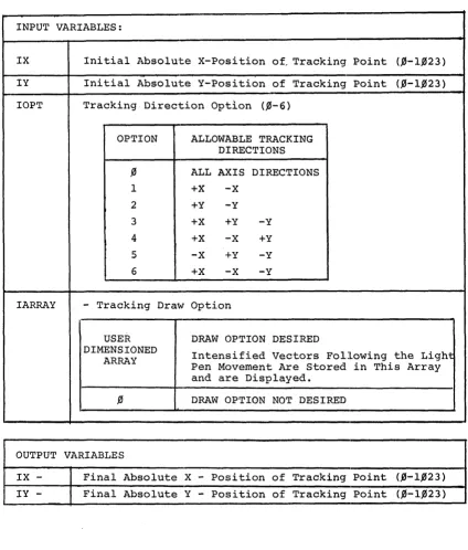
4.2 TRACK SUBROUTINE
The TRACK subroutine is used for light pen tracking or drawing. Tracking being
the input of an x-y coordinate where the tracking pattern is to be initially
displayed. The user then moves the tracking pattern with the light pen to the
desired location; and presses a pushbutton to escape from the tracking
sub-routine. The final x-y coordinate is then returned through the x-y input
arguments. Drawing is the same as tracking with the addition of an array
stor-ing the vectors which describe the trackstor-ing path, (the path is displayed durstor-ing
tracking). The vector array is structured the same as a subpicture file and
may be recalled by the user. The array must be dimensioned by the calling
program, keeping in mind the number of vectors that will be inserted into it. A straight line requires an array of seven locations. 'rhe form of the call
statement to track is as follows:
CALL TRACK (IX, IY, IOPT" IARRAY)
Use of the TRACK subroutine requires four arguments. ~NO already mentioned
are the initial x coordinate and the initial y coordinate; these are also
used as return arguments of the final x coordinate and final y coordinate. The
third required argument is the direction option which allows the user to restrict
movement of the tracking pattern in certain directions. The direction option
is also used to draw straight lines in the horizontal or vertical direction.
If the value of the direction i.s zero, tracking is allmrVed in any direction.
A description of the direction options available can be found in Table 4.1
(Input Variables) . The fourth required argument indic(~tes whether the draw
option is desired. A zero indicates tracking only. If drawing is desired,
will be stored. Examples of the use of these arguments can be found in the
following sample program that calls TRACK.
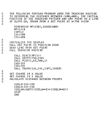
C
THE FOLLOWING FORTRAN PROGRAM USES THE TRACKING ROUTINE
C
TO DETERMINE THE DISTANCE BETWEEN (100,400), THE INITIAL
C
POSITION OF THE TRACKING PATTERN AND ANY POINT ON A LINE
C
OF SLOPE 20, DRAWN FROM A SET POINT AT
X=750Y=250
C
C
DIMENSION MF(150),IUSER(200)
MF'(!)=0
IOPT=3
IXl=100
IYl=400
C
INITIALIZE THE DISPLAY
C
CALL SET POINT TO POSITION BEAM
C
DRAt,] LI NE FR ot-1 SET POI NT
C
CALL TRACKING ROUTINE
C
C
CALL DINIT(MF(l»
CALL SETPT(750,250)
CALL PLOT(I,25,500,1)
IX2= IXI
I Y2= IYl
CALL TRACKCIXl,IY1,IOPT,IUSER)
C
GET CHANGE IN X VALUE
C
GET CHANGE IN Y VALUE
C
CALCULATE DISTANCE BETWEEN POINTS
C
I DELX= IXl- IX2
I DELY= I Y 1- I Y2
IDELAB=SQRT(CIDELX**2)+(IDELY**2»
STOP
END
[image:42.623.121.504.115.562.2]Table 4.1 Description of CALL TRACK Arguments
Example:
CALL TRACK (IX,IY,IOPT,IARRAY)
INPUT VARIABLES:
IX Initial Absolute X-Position of, Tracking Point (,0-1,023)
IY Initial Absolute Y-Position of Tracking Point (,l'j-l,l'j23)
IOPT Tracking Direction Option (,l'j-6 )
OPTION ALLOWABLE TRACKING DIRECTIONS
,l'j ALL AXIS DIRECTIONS
1 +x -X
2 +Y -Y
3 +X +Y -Y
4 +X -X +Y
5 -X +Y -Y
6 +x -x -Y
IARRAY - Tracking Draw Option
USER DRAW OPTION DESIRED
DIMENSIONED
Intensified Vectors Following the Light ARRAY
Pen Movement Are Stored in This Array and are Displayed.
,l'j DRAW OPTION NOT DESIRED
OUTPUT VARIABLES
IX - Final Absolute X - Position of Tracking Point (,0-1,023) IY - Final Absolute Y - Position of Tracking Point (,0-1,023)
[image:43.620.108.532.158.656.2]