437
RGB-D IMAGE BASED LANDMARK IDENTIFICATION
FOR CORRIDOR COVERAGE NAVIGATION
1MUHAMMAD FUAD, 2RUSDHIANTO EFFENDI A.K., 3DJOKO PURWANTO 1
Faculty of Engineering, University of Trunojoyo Madura, Indonesia
2, 3
Electrical Engineering Department, Faculty of Industrial Technology, Institut Teknologi Sepuluh Nopember Surabaya, Indonesia E-mail: [email protected] , [email protected]
ABSTRACT
Developing robotic coverage navigation system in straight corridor using only one sensor, RGB-D camera, is a challanging problem. System must be able to identify the landmarks that naturally exist in structured environment. This ability is needed to provide the information about perimeters of workspace that should be covered by robot in a single task at segmented area of corridor. Color detection and distance estimation using RGB-D images are applied to identify landmarks that found in corridor. Identification is calculated from salient region that covered 0.125 of images area. Landmarks in range between 0.8 to 5.6 meters have successfully identified with accuracy 98.86%.
Keywords: Coverage Navigation, RGB-D Images, Landmarks, Straight Corridor, Structured Environment.
1. INTRODUCTION
Navigation can be described as ability to guide man, machine, or robot to move from source location to destination. This capability that lead robot to pass over all points of a certain area of interest is known as coverage navigation. Choset classified algorithms to cover as off-line and on-line [1] based on the availability of all stationary and environment information. The first category has requirements that might be unrealistic in a large number of scenarios that it assumes full prior knowledge of operation area to be known in advanced. In a contrary, the second category does not need to take for granted requisite data completely because it utilizes real-time sensor measurements to explore the workspace. One important issue in navigating robot that can be expressed as competence to determine position of the robot itself in the environment is self-localization [2]. This problem can be solved by detect unique features, known as landmarks, in the environment. A way of navigation with localization that consists of identifying and following sequence of landmarks is known as piloting. The problem shifts to how to choose consistent landmark. Some researchs about navigation techniques based on landmark are resumed in next section.
Predesigned landmark is a simple approach in piloting by adding unique patterns as artificial landmark in the environment. Geometry patterns that were set as landmark had been investigated by Lazanas and Latombe [3] and Magee and Aggarwal [4]. Taylor and Kriegman proposed barcode as landmark [5]. QR code was placed in ceiling and adjust Kinect sensor to detect this landmark was examined by Eric McCann et al [6].
438 This research aims to identify selected landmark using RGB-D images from single Kinect sensor to achieve high accuracy and inexpensive computation for supporting corridor coverage navigation. To achieve the aims, this study seeks to determine a method to integrate landmark identification based on RGB and Depth images; and to use the result of landmark identification to control velocity of forward and rotation movement of robot.
The remainder of this paper is structured as follows. Section 2 describes previous research. Section 3 explains the technique that is used for identifying the landmarks based on RGB-D images. The method of velocity and rotation control is described in Section 4. Section 5 reports the experiments and results of landmark identification for corridor coverage navigation. And finally, some concluding remarks is stated in Section 6.
2. PREVIOUS RESEARCH
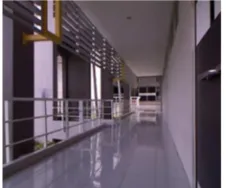
[image:2.612.139.253.405.499.2]In our previous work [14], wall-following behaviour that comprised ability to estimate distance and heading angle was implemented using Kinect. Experiments was conducted in straight corridor, Figure 1, that half of its side was in open condition therefore sun light can come in.
Figure 1: Operation Area of Omnidirectional Vacuum Cleaning Robot
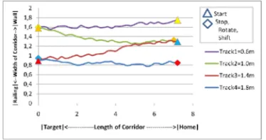
The open side of corridor has perimeters that was constructed with railing in the top and bottom parts. While the other side was consisted of wall with some doors. There are four reference path that had been tracked using wall-following without landmark identification to tell the system when to start covering, stop moving, or shift to the next path. This research proposes landmark identification based on RGB-D images from Kinect sensor. Straight corridor is the workspace that vacuum cleaning robot has to cover as much as area of the floor without collide with perimeters. As suggested by Wong and MacDonald [15] to use slice decomposition of workspace based on natural landmarks, our research is dividing long straight corridor into some rectangular regions that have naturallandmarks
.
Contrasts with Wong and MacDonald's approach to utilize corners of testbed environment as landmarks [16], Todt and Torras [17] took advantage of visual attention multi resolution mechanism in color contrast for extracting salient region of images. Salient detection based on color in Todt and Torras's experiment had been applied not only to still image but also to motion images that got while robot moved. Salient region works as filter to find landmarks in images. Saliency of a region does not depend on absolut value of intrinsic magnitude but relies on contrast or difference between values in this region and its neighbour. Color component, intensity, or feature orientation are some variables that can be used to determine saliency of a region.
Our research proposes to exploit salient parts of corridor's perimeters as naturally exist landmarks. Corridor in this research comprise floor, ceiling, wall, and railing. Figure 1 shows corridor image that is captured from Kinect sensor on the top of omnidirectional mobile robot. Tilt angle of this sensor is set to 0°. Ideal landmark must be unique and be identified easily with the intention that navigation action can be taken precisely.
The ideal landmark must be unique in order to be recognized easily so that navigation action decision can be taken properly. Natural landmark is a form landmark that may appeared as unique part of building structure in the workspace environment. Figure 1 shows corridor comprise yellow block in each pillars have contrast color compared to other thing around it.
3. LANDMARKS IDENTIFICATION BASED
ON RGB-D IMAGES
[image:3.612.294.521.44.265.2]
439
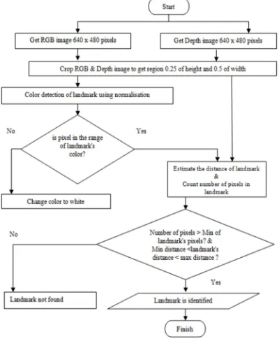
Figure 2: Block Diagram Of Corridor Navigation System
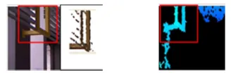
Distance estimation and color detection are used in this research as techniques to extract landmark. Estimation of each object's pixels is achieved by applying piece wise exponential conversion formula from hue value of Depth image to distance in cm's as had been investigated in earlier research [14] with average error 1.14% or accuracy 98.86%. Contrast of environment's color was detected by harnessing color detection in RGB image in order to acquire binary image contains landmark. Steps in color detection is started by getting Red, Green, Blue colors from each random pixels from landmark candidate. Pixel value of each color component is divided by sum of three colors to obtain normalisation. Minimum and maximum value of normalisation are determined in such a way pixels in these ranges will be kept whereas the others will be ignored. Color of yellow blocks can be observed from Depth images since the railing surround it will be displayed in black so that the yellow blocks will be salient. Figure 3 presents yellow blocks as landmarks that viewed in RGB (left) and Depth (right) images.
[image:3.612.86.533.55.251.2]
Figure 3: Landmarks in RGB and Depth Images
[image:3.612.94.298.69.220.2]By using distance estimation, landmark extraction process proceed with taking of 16 samples of Depth images as shown in Figure 4. The number of samples are representation of tracks in the corridor against combination of starting and finishing location of each navigation task. Landmark always appeared in the same region in all images, that is in position 0.25 of image's height and 0.5 of image's width in the right or left side.
Figure 4: Measuring Distance Of Landmarks.
The first four measurements, as illustrated in top rows of Figure 4, were carried out at start location of every track in the corridor navigation task from home to target with the wall in the right side of robot. There are four tracks that must be covered. Each of them have distance 0.6 m, 1.0 m, 1.4 m, and 1.8 m to the wall [14]. The second four measurements were performed at finish location with the same direction of navigation task and the same relative position of robot with respect to wall. A pair of four measurements were executed from target to home with the wall in the left side of robot. There are two groups of unique values, min and max, that are the results of distance estimation, color detection, and experiment of robot's heading effects in corridor. Range of landmark's color in Red, Green, Blue components are displayed in Table 1.
Table 1. Range of Landmark's Color Component
Color Min Max
Red 0.42953 0.55102
Green 0.227273 0.380597
Blue 0.074627 0.306818
[image:3.612.306.528.515.599.2] [image:3.612.113.277.520.572.2][image:4.612.91.289.74.195.2]
440
Figure 5: Number Of Landmark's Pixels In Binary Images
Uncertainty factor of RGB-D camera causes difficulties to precisely determined landmark's distance of every location that robot may cover. Valid landmarks have been recorded to be identified in ranges as describes in Table 2.
Table 2. Range Of Landmark's Distance
Robot's Relative Position Min (m) Max (m)
Wall in the right side of robot 3.7 4.5 Wall in the left side of robot 2.7 3.7
[image:4.612.312.524.217.339.2]The measurement of Depth images in some locations, robot facing end of corridor with the wall in the right side, return distance between robot and landmark in range 3.7 m until 4.5 m. While other measurements, robot facing end of corridor with the wall in the left side, produce gap 2.7 m and 3.7 m in minimum and maximum respectively. Flowchart of landmark identification process utilize RGB-D images is drawn in Figure 6. Outcome of this process is used as input to control velocity and rotation.
Figure 6: Landmark Identification Process
4. VELOCITY AND ROTATION CONTROL
Cell-decomposition area in straight corridor as workspace of vacuum cleaning robot is illustrated in Figure 7. Robot utilize boustrophedon strategy for covering this area. Consequently, it requires to control velocity and rotation. This ability will help robot to start and stop it's wall-following based on the result of landmark identification.
Figure 7: Cell-Decomposition Area In Straight Corridor.
[image:4.612.315.528.434.522.2]Start-stop controller is employed to facilitate this requirement. Constant velocity 0.12 m/sec on forward direction is applied when the first landmark successfully identified. If the second landmark is detected then this velocity turn to 0 m/sec. Therefore the robot will stop and rotate 180° to continue to the next track as shown in Figure 8.
Figure 8: Boustrophedon Strategy For Covering This Area
[image:4.612.92.292.467.711.2]441
[image:5.612.90.531.73.393.2]Figure 9: State Diagram Of Corridor Coverage Navigation
Figure 10: Corridor Coverage Navigation Algorithm
5. EXPERIMENTS AND RESULTS
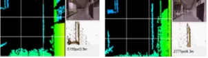
[image:5.612.120.271.604.646.2]The first experiment of landmark identification based on RGB-D images is accomplished by examining synchronization between RGB color detection and Depth distance estimation. Two of sixteen samples that are brought in Figure 11 demonstrate ability to identify landmarks in start and stop position of the first track. Landmarks are detected at distance 3.92 m and 4.3 m with 5195 and 2771 in number of pixels respectively.This experiment is done before testing the ability to support navigation. This approach use single sensor that is facing forward bring enhancement compare to [6] in ability to identify naturally exist landmark without any artificial landmark addition in structured environment.
Figure 11: Identifying Landmark At Start And Stop Position In First Track
Capability to identify landmark in condition where obstacles are added in workspace is investigated in second experiment as displayed in Figure 12. Because of it's position is higher than the obstacle(s), landmarks able to be detected at
distance 2.91 m and 3.91 m with 3380 and 4068 in number of pixels respectively. This strategy can compete with results of [12] in the emergence of obstacles without loosing time in training.
Figure 12: Landmark Is Detected When Obstacle(S) Is Added In Workspace
The third experiment is executed to test performance of system in situation where robot position does not align with corridor axis due to drift error. Figure 13 proves that system able to recognize landmark even when heading direction of robot swing over in some angles from top to bottom, those are 0°, -4°, and 3°. This method shown an improvement to answer problem of the appearance/disappearance of regions when changing the point of view as happened in [10].
Figure 13: Landmark Is Recognized In Drift Error Situation
[image:6.612.188.521.66.727.2]
442
Figure 14: Landmark Identification In Real-Time Application
Figure 15: Landmark Identification In Trajectories Of Corridor Coverage Navigation
6. CONCLUSIONS
Landmark in workspace in the form of building structure that having unique characteristics in color and position can be identified by landmark identification that combine color detection and depth distance estimation. System that has been developed in this research is capable to detect landmark in off-line, even when obstacles are added in workspace or when heading direction is swing over. According to the result of real-time application, RGB-D images based landmark identification able to be used in coverage navigation in straight corridor without adding artificial landmark in environment. Computation of landmark identification is done by exploiting salient region that covered 0.125 of images area. Accuracy 98.86% is achieved in detecting landmarks that stand in range between 0.8 to 5.6 meters. However, system still require to be enhanced in capacity for learning to decide which elements of environment that can be choosed as landmark.
REFERENCES:
[1]. H. Choset, “Coverage for Robotics – A Survey of Recent Results”, Annals of
Mathematics and Artificial Intelligence 31:
113 - 126, Kluwer Academic Publishers, Netherlands, 2001.
[2]. R. Siegwart, I. R. Nourbakhsh, Introduction to
Autonomous Mobile Robots., MIT Press,
Cambridge, Massachusetts, 2004.
[3]. Lazanas, A. and Latombe, J.C. "Landmark-based robot navigation". In: 10th National
Conference on Artificial Intelligence, San
Jose, CA, pp. 697–702. 1992.
[4]. Magee, M. and Aggarwal, J.K. "Robot self-location using visual reasoning relative to a single target object", Pattern Recognition, 28(2):125–134. 1995.
[5]. Taylor, C.J. and Kriegman, D.J. "Vision-based motion planning and exploration algorithms for mobile robots". In: Workshop on the
Algorithmic Foundations of Robotics. 1994.
[6]. Eric McCann, Mikhail Medvedev, Daniel J. Brooks and Kate Saenko, "Off the Grid: Self-Contained Landmarks for Improved Indoor Probabilistic Localization". 2013.
[7]. Nasr, H. and Bhanu, B. "Landmark recognition for autonomous mobile robots". In: IEEE Intl.
Conf. on Robotics and Autom., pp. 1218–1223.
1988.
[8]. Bouguet, J.Y. and Perona, P. "Visual navigation using a single camera". In: Proc.
Intl. Conf. on Computer Vision, pp. 645–652.
1995.
[9]. Kortenkamp, D., Weymouth, T. "Topological mapping for mobile robots using a combination of sonar and vision sensing". In: Proceedings of the 12th National Conference on Artificial
Intelligence (AAAI’94), Seattle, Washington,
pp. 979–984. 1994.
[10].Enric Celaya, Jose-Luis Albarral, Pablo Jim´enez, and Carme Torras. "Natural Landmark Detection for Visually-Guided Robot Navigation", Springer-Verlag Berlin Heidelberg, pp. 555–566. 2007.
[11].Thrun, S. "Bayesian landmark learning for mobile robot localization". Machine Learn. 33 (1), 41–76. 1998.
[image:6.612.102.289.293.392.2]443 [13].Gareth J. F. Jones, Daragh Byrne, Mark
Hughes, Noel E. O'Connor, and Andrew Salway, "Automated Annotation of Landmark Images using Community Contributed Datasets and Web Resources". 2011.
[14].M. Fuad, D. Purwanto, “Wall-Following using a Kinect Sensor for Corridor Coverage Navigation”, Journal of Theoretical and
Applied Information Technology, Vol. 70, No.
1, 2014, pp. 106 - 111.
[15].S.C. Wong, B.A. MacDonald, "Complete coverage by mobile robots using slice decomposition based on natural landmarks", in: C. Zhang, H.W. Guesgen, W.-K. Yeap (Eds.), PRICAI 2004: Trends in Artificial Intelligence,
in: Lecture Notes in Computer Science, vol.
3157, Springer, Berlin, Heidelberg, 2004. pp. 683–692. http://dx.doi.org/10.1007/978-3-540-28633-2_72.
[16].S.C. Wong, B.A. MacDonald, "A topological coverage algorithm for mobile robots", In:
Proc. IEEE/RSJ Int. Conf. Intelligent Robots
and Systems, IROS2003, Vol. 2, 2003, pp.
1685–1690.
[17].Todt, E., Torras, C., "Detecting Salient Cues Through Illumination-Invariant Color Ratios".
Robotics and Autonomous Systems 48(2-3),