BONE FRACTURE DETECTION USING OPENCV
1SAMUEL FEBRIANTO KURNIAWAN, 2I KETUT GEDE DARMA PUTRA
, 3 A.A KOMPIANG OKA SUDANA
1,2,3
Department of Information Technology, Udayana University, Indonesia
E-mail: [email protected]
,
2
,
3
ABSTRACT
Image processing is important in modern data storage and data transmission especially in progressive transmission of images, video coding (teleconferencing), digital libraries, image database, and remote sensing. The purpose of this project is to find out the accuration of an X-Ray Bone Fracture Detection using Canny Edge Detection Method. Fractured bone is a bone condition that suffered a breakdown of bone integrity. A disconnected connection between two cartilages also categorized as bone fracture. Normally, bones have elasticity and a great number of strength. Bone fracture only happen when the bones took a force beyond their elasticity or strength. This system is built using OpenCV library combined with Canny Edge Detection method to detect the bone fracture. Canny Edge Detection method is an optimal edge detection algorithm on determining the end of a line with changeable threshold and less error rate. The simulation results have shown how canny edge detection can help determine location of fractures in x-ray images.
Keywords: Fracture, Edge, Edge Detection, Canny, Threshold, x-ray images.
1. INTRODUCTION
Digital image processing is an expanding area with applications regarding to our daily lives, especially in progressive transmission of images, video coding (teleconferencing), digital libraries, image database, remote sensing, and other particular applied usage. Many image processing and analysis techniques have been developed to aid the interpretation of remote sensing images and to extract as much information as possible from the image. The huge collection of digital images are collected due to the improvement in the digital storage media, image capturing devices like scanners, web cameras, digital cameras and rapid development in internet. This leads to rapid and efficient retrieval of these images for visual information in different fields of life like medical, medicine, art, architecture, education, crime preventions, etc [1,2].
The medical imaging field has grown substantially in the recent year and has generated additional interest in methods and tools for management, analysis, and communication of medical image. Many diagnostic imaging modalities, such as x-ray, magnetic resonance imaging (MRI), digital radiography, and ultrasound
are currently available and are routinely used to support clinical decision making. By using medical imaging, physicians are able to glean qualitative and quantitative information about anatomy and physiology of the patients. With this advantages, medical imaging has become central to medical diagnosis. Thus, with the advances in computer processing capabilities, it has become possible to approach the problem of automating diagnosis in medical imaging. This paper will focus on canny edge detection that help radiologist in automated diagnosis image. Radiologist often experiencing difficulty on reading x-ray image. This can be caused by the lack of lighting, fractures the hardly seen by naked eyes, or noises the happened on image capturing process. By building the system, we hope the system can help people especially radiologist on detecting bones anomaly that happened on x-ray images [3].
2. IMAGE PROCESSING TECHNIQUE
Image processing techniques are employed to develop this algorithm. It is discussed in detail in this section.
2.1 Canny Edge
Edges are considered to be most important image attributes that provide valuable information for human image perception. Edge detection is a very complex process affected by deterioration due to different level of noise [4]. An edge is the boundary between an object and the background. Edge detection is identifying points in a digital image at which the image brightness changes sharply or more formally has discontinuities. The purpose of detecting sharp changes in image brightness is to capture important events and changes in properties of the world [4].
Edge detection is used for identification of blurred frame broad classification among smooth and rough surface classification of cement and asphalt. The Canny edge detection is performed on the frames with the sensitive threshold values (upper threshold 10000 and lower threshold 4900) and again it is performed with the insensitive threshold values (upper threshold 50000 and lower threshold 9800) [4]. If a pixel has a gradient greater than the upper threshold, then it is an edge pixel. If a pixel has a gradient lower than the lower threshold, it is not an edge pixel. If the pixel’s gradient is between the upper and the lower thresholds, then it is considered as an edge, only if it is connected to a pixel that is above the high threshold value as given in [5,11].
Canny is one of modern edge detection method that founded by Marrdan Hildreth, who is doing research in modeling human visual perception. There are several criteria on edge detecting that can be fulfilled by Canny Edge Detection:
1. Canny has better detection (for detection criteria). Canny method capable to marks all existing edges matching with user determined parameter’s thresshold. Also giving high flexibility on determining thickness level of edge detection according to the required conditions.
2. Canny has better localizing way (localize criteria). Canny capable on producing minimum gap between detected edge and the real image edge.
3. Obvious response (response criteria). Only one response for every edge. This make less confusion on edge detection for the next image. Chosing parameters on Canny Edge Detection
will giving effect on every result and edge detection. The parameters are :
a. Gaussian Deviation Standard Value. b. Thresshold Value.
The following is the steps to do Canny Edge Detection.
1. Remove all noise on the image by implementing Gaussian Filter. The result is an image with less blur. It is intended to obtain the real edges of the image. If we did not apply the Gaussian Filter before, sometimes the noise itself will be detected as an edge.
2. Detect the edge with one of these detection operators, like Roberts, Perwit, or Sobel by do horizontal searching (Gx) and vertical searching (Gy). The following is the sample of edge detection operator (Sobel operators).
(a) (b)
Figure 1 Sobel Operator (a) Gx, (b) Gy
The result from both operators combined to obtain the summary of vertical edge and horizontal edge with this formula[6]:
(3)
3. Determining direction of the edge by using the following formula:
ଶ ଶ (4)
ீ௬
ீ௫ (5)
Canny Edge Detection using two thresholds (maximum threshold and minimum threshold). If pixel gradient higher than maximum threshold, pixel will be marked as an edge. If the pixel gradient lower than minimum threshold, the pixel will be denied as background image. If the pixel gradient between maximum threshold and minimum threshold, the pixel will be accepted as an edge if it is connected with other edge pixel that higher than maximum threshold.[11]
5. The last step is binarizing the image pixels by applying two threshold value.
2.3 System Overview
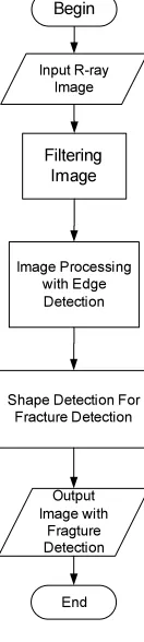
System overview of this program is discussed in detail in this section.The next figure show the system design in flowchart. This flowchart explain the process flows from detecting X-ray image until producing the bone fracture detection on the X-ray image.
Input R-ray Image
Filtering Image
Image Processing with Edge Detection
Shape Detection For Fracture Detection
Output Image with
Fragture Detection Begin
[image:3.595.165.231.243.537.2]End
Figure 2 Flowchart System
Here is an explanation of the performance of the system:
1. First user must input an image to be processed, the image will then be carried filtering to remove noise that exist in the image.
2. The next step will performed after image filtering process, the image will be processed using Canny Edge method, it will give results more visible lines on an X-ray image.
3. The system then combines the results of early detection canny with the original image, then user can clearly see the shape of the bone and this combined images will be processed by the system.
4. To detect the location of the fracture in the image, the system use shape detection with multiple parameters. A broken bone is expressed
when the line has an end, and do not have a connection with another line. A broken bone stated, if the lines form an angle less than 145 degrees, although the line still has a connection with the other lines.
5. The parameters on system specify in determining the location of the broken bone is as follows:
a. The red color, indicating the location after the end of a line through a process canny edge detection. Where the line is only a single line and doesn’t have adjacent to any other lines.
b. The blue color indicates the location of the end of a line next to each other (this is intended to indicate the location of the line that has the possibility of having a hairline fractured bone).
c. The green color indicates the location of the end of a line in the line has a lot of ends. The amount of a tip in the first line helps the system to recognize the location of a major fracture in the picture.
This system builds from OpenCv library, CV namespace contains image processing and camera calibration methods. The computational geometry functions are also located here. CVAUX namespace is described in OpenCv's documentation as containing obsolete and experimental code. However, the simplest interfaces for face recognition are in this module. The code behind them is specialized for face recognition, and they're widely used for that purpose. ML namespace contains machine-learning interfaces. HighGUI namespace contains the basic I/O interfaces and multi-platform windowing capabilities. CVCAM namespace contains interfaces for video access through DirectX on 32-bit Windows platforms.[7,8]. In book of [13,14,15] there much information about using OpenCv for build this system. Here is an example pseudocode from OpenCv that determining the location of the broken bone.
//Setting the parameter for edge detection
CV_POLY_APPROX_DP,
cvContourPerimeter(contours)*0.05, 0);
//Red Point detection indicating for edge detection
if(result->total==2 )
{
CvPoint *pt[2]; for(int i=0;i<3;i++){
pt[i] = (CvPoint*)cvGetSeqElem(result, i); }
// blue point detection, indicating for hairline fracture bone
if(result->total==3 )
{
CvPoint *pt[3]; for(int i=0;i<3;i++){
pt[i] = (CvPoint*)cvGetSeqElem(result, i); }
//Green Point detection, indicating for major fracture
else if(result->total==4 )
{
CvPoint *pt[4]; for(int i=0;i<4;i++){
pt[i] = (CvPoint*)cvGetSeqElem(result, i); }
[image:4.595.192.502.106.493.2]3. RESULT
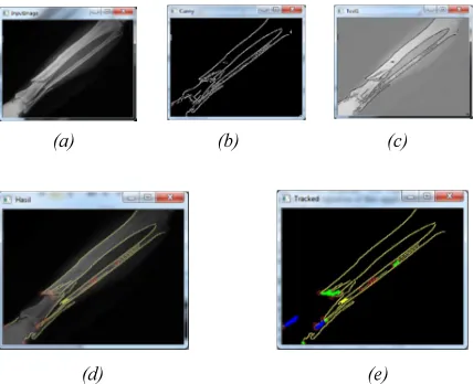
Figure 3 shows step 1 – 5 in chapter 3 to start the bone fracture detection process. The first image output has been processed through Canny Edge Detection method, and then followed by the shape detection. Shape detection used to find the end of a line. End of a line can be ascertained as the position where the fracture occured. This application can reduce the unused parameter that categorized as undamaged part (chapter 2).
There are many outputs from this proses, which are the original image to be processed, 2 images that has been processed by Canny Edge Detection method, and 2 images that shows the user the result of fracture detection. Figure 3 will show those 5 outputs.
In figure 3 the user uploads an x-ray image, figure 3(a). Then system will process that image
with Canny Edge detection, figure 3(b). In figure 3(c) system shows the output of image processing, by combining the image of canny edge detection result and inverting the original image that uploaded by the user. In figure 3(d) system will detect the location of the end of each line. In Figure 3(e) the system will then automatically detect fractured bone and its location.
(a) (b) (c)
(d) (e)
Figure 3 (a) Input Image (b) Output Image with canny Detection(c) Invert Output Image Canny Detection (d) Output image with canny Detection with edge detection in every edge (e) Output image with Fracture detection.
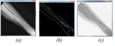
To clarify the performance of the system, we decided to process the other images. Here is an example of the results of the image processing:
[image:4.595.299.508.229.493.2] [image:4.595.300.498.625.705.2](d) (e)
Figure 4 (a) Input Image (b) Output Image with canny Detection(c) Invert Output Image Canny Detection (d) Output image with canny Detection with edge detection in every edge (e) Output image with Fracture detection.
(a) (b) (c)
(d) (e)
Figure 5 (a) Input Image (b) Output Image with canny Detection(c) Invert Output Image Canny Detection (d) Output image with canny Detection with edge detection in every edge (e) Output image with Fracture detection.
After a number of attempts to detect the location of the fracture, the results of the experiments are summarized in Table 1.
Table 1 Result of Fracture Detection
No End Of Line Detection
(Red)
Hairline Fracture Detection
(Blue)
Fracture Detection
(Green)
1 11 Edge
Detection
None Hairline Fracture Detection
6 Major Fracture Detection
2 22 Edge
Detection
1 Hairline Fracture Detection
9 Major Fracture Detection
3 15 Edge
Detection
2 Hairline Fracture Detection
3 Major Fracture Detection
Table 1 shows the number of results of the detection system bone fracture, and accuracy of system detection can be seen in Table 2.
Table 2 Accuracy of Fracture Detection
No Hairline Fracture
(a)
Major Detection
(b)
Accuracy
True False True False A b
1 - - 4 2 - 50%
2 1 - 5 4 100% 55,6%
3 1 1 2 1 50% 66,7%
4. CONCLUSION
This Paper presented the Canny Edge detection framework to assist radiologist in detecting fractured bones from x-ray images. It has been tested with real data. Simulation result shows that the system need to be improvised on it performance and reduce the response time.
According to the test result that has been done to detect the bone fracture, a conclusion can be made that the performance and accuration of the detection method affected by the quality of the image. The better the image quality, the better result system got.
For the future development, there are some things that must be noted:
a. Implement another image processing method in order to improve the accuration of image detection.
b. Adding various language will capable on supporting the integration of this application to other application or system.
c. Improvise the method performance to decrease the amount of time and decrease the percentage of error by adding several model of different neural networks trained with different architecture before initiating this system.
REFRENCES:
[1] Mubeena Pathan, K.Jusoff, M. S. Alias ”Implication Of Image Processing Algorithm In Remote Sensing and gis applications”, Journal of Theoretical and Applied Information Technology, 15th December 2011, vol 34 No 1.
[image:5.595.79.512.80.439.2] [image:5.595.77.291.262.436.2][3] Mostafa Syiam, “AdAgen : Adaptive Interface Agent For X-Ray Fracture Detection”, International Journal of Computing & Information Sciences, December 2004, vol 2, no 3.
[4] Dhanabal R,” Digital Image Processing Using Sobel Edge Detection Algorithm In Fpga “, Journal of Theoretical and Applied Information Technology, 10th December 2013, Vol. 58 No.1.
[5] Rafael C. Gonzalez, Richard and E. Woods, “Digital Image Processing”, Third Edition, 2009.
[6] Batra Yudha Pratama,”Pendeteksian Tepi Pengolahan Citra Digital “, 2007, Komunitas eLearning IlmuKomputer.Com.
[7] Robin Hewitt, 2010, Available at :http://www.cognotics.com/opencv/servo_2007 _series/part_1/index.html 2010/09/02.
[8] Shervin Emami,”Facial Recognition using OpenCV”, Journal of Mobile, Embedded and Distributed Systems, vol. IV, no. 1, 2012. [9] Bin Yu and Anil K. Jain, “Lane Boundary
Detection Using A Multiresolution Hough Transform,” Dept. of Computer Science Michigan State University, East Lansing, MI 48824, IEEE Conference, October 1997, vol. 2, pp. 748-751.
[10] N. Otsu, “A threshold selection method from grey-level histograms”, IEEE Trans. Syst., Man, Cybern, Vol. SMC-8, 1978, pp. 62–66. [11] Darma Putra,“Pengolahan Citra Digital”.
Andi. Yogjakarta, Indonesia, 2010.
[12] Xuan Mo, “OpenCV Tutorial I: Image Processing”, iPal Grub Meeting , 2011. [13] David Stavens,” The OpenCV Library:
Computing Optical Flow”, Stanford Artificial Intelligence Lab, 2013.
[14] Robert Laganière,” OpenCV 2 Computer Vision Application Programming Cookbook”. Packt Publishing , 2011.
[15] Klaus D. Toennies, “Advances in Computer Vision and Pattern Recognition”. Springer-Verlag, London, 2012.