United States Patent
[19]Lawrence
[54] PEAK DETECTOR
[75] Inventor:
[73] Assignee:
Charles E. Lawrence, Boerne, Tex.
Datapoint Corporation, San Antonio, Tex.
[21] Appl. No.: 53,545
[22] Filed: Jun. 29, 1979
[51] Int.
a.
3 ... H03K 5/153 [52] U.S.a ...
328/150; 307/351; 307/354; 328/114 [58] Field of Search ... 307/351, 354; 328/114, 3281132, 150, 117, 167; 324/103 P; 360144, 42[56] References Cited
3,281,806 3,304,542 3,373,415 3,864,583 4,112,381
U.S. PATENT DOCUMENTS
10/1966 2/1967 3/1968 2/1975 9/1978
Lawrance et aI ... 360/44 Sutton et aI ... 360/44 Gabor ... 360/44 Fiorino ... 307/232 X Mortensen et al. ... 328/150
OTHER PUBLICATIONS
P. T. Marino, Data Demodulation Employing Integra-tion Techniques, IBM Technical Disclosure Bulletin, vol. 17, No.2, JuI. 1974, p. 453.
B. C. Fiorino, Detection of Digital Data Using Integra-tion Techniques, IBM Technical Disclosure Bulletin, vol. 16, No.7, Dec. 1973, pp. 2416-2417.
S. Av et aI., Data Detection Circuit, IBM Technical
C
T
10
[11]
[45]
4,262,257
Apr. 14, 1981
Disclosure Bulletin, vol. 18, No. 11, Apr. 1976, pp. 3821-3822.
Primary Examiner-John Zazworsky
Attorney, Agent, or Firm-Soules, McCamish, Ingram, Martin & Brown, Inc.
[57] ABSTRACT
A peak detecting network utilizes a passive integrating filter to translate the peaks of an input signal into zero crossings of a translation signal, while providing a high degree of noise. rejection and preventing the build-up of a DC component in the translation signal. The peak detecting network includes a sine pulse-forming filter comprised of a parallel cascade of a DC shunt inductor, a plurality of series LC sections, and a terminating ca-pacitor. The series LC sections are characterized by respective transfer functions whose impulse responses are substantially finite time duration sine pulses of a successive number of cycles. A rectifier network ap-plies a rectified input signal to the sine pulse-forming filter. A buffer network taps the response of the LC section associated with a one-cycle sine pulse impulse response. The resulting translation signal has a positive-going zero crossing corresponding in time to the occur-rence of a peak of the rectified input signal. A positive-going zero crossing detector then detects the sequence of positive-going zero crossings of the translation signal in order to retrieve the sequence of the peaks of the input signal.
11 aaims, 3 Drawing Figures
30
POSITIVE GOING
ZERO CROSSING DETECTOR
20
r---
22----
24-r~-=---=;---L-1
I
f{t) I II
I
PHASE \Q25 :I
f{t)I--+--I INVERTER -f(t) : I
I
I
I R20I
I
~~~
__
J
-"J
u.s.
Patent
Apr. 14, 1981
4,262,257
10-I
IA
I
I
I
I
I
I
I
I
I
I
I
I
I
II
II
I
I
I
I
I II
I
I
I
I
I
I
I
I
I
B~~
I
I
I
I
I
II
II I I , I
I
I Ito
tl t2 t3 t4 t5 t6tr
t8I I I I
I
I
II
c
jW'\
V\
i/\ 1\1\
v\
fllt
I
:\11
~~M
V:~\f:
M]
I
II
I
I
I
I I
II I
I
I
I I I
DOnnnnODO[
FIG ..
3)
T~
f(t)
PT(t)
PO (t)
f ( t } - - - I
ZERO -30 ---ilCROSSING
DETECTOR
T~
T~
F][G .. IL
10
30
POSITIVE GOING
ZERO
CROSSINGDETECTOR
20
r - - - -
...L_,
I 22 24
r---,
II
f{t)i
I
I
I
PHASE lQ25 :I
f(t)-1--I
INVERTER
-f(t) : II
I
:
R20I
I
1 Q 2 6 - VL _____________
L_-=-=~_______
~1
2
PEAK DETECfOR
FIELD OF THE INVENTION
detector merely compares the integrator signal to a fixed ground or reference level, then peak detection is susceptible to errors caused by a sufficiently large DC component of the integrator signal. Additional errors The present invention generally relates to peak
de-tecting networks, and more particularly to peak detect-ing networks that perform an integration of an input signal in order to provide a zero crossing indication of the occurrence of a signal peak while reducing the effects of superimposed noise.
5 may result because the slowly varing DC component causes some peaks to be detected earlier or later in time than their actual time of occurrence. The latter situation is particularly unacceptable in those applications, such as the data processing application mentioned above, in
BACKGROUND OF THE INVENTION In many communications and data processing appli-cations it is necessary to accurately detect the peaks of
10 which the accurate retrieval of the information con-tained in an input signal depends upon preserving the precise peak phase relationships of the input signal. Accordingly, in order to take advantage of the inherent
an input voltage signal. For example, the process of 15 reading digital data written onto a recording medium, such as a disc, results in an alternating read signal in which the information is contained in the phases of the signal peaks. The information is recovered by applying the read signal to a peak detecting network that pro- 20 vides a sequence of indications, typically in the form of logic level transitions, corresponding in time to the peaks of the input read signal.
The actual detection of the peaks of an input signal is frequently accomplished by translating these peaks into 25 corresponding zero crossings of a peak detector signal, and thereafter sensing the occurrence of the resulting zero crossings by means of a compar.ator network. The translation of the input signal peaks into zero crossings of the peak detector signal is typically accomplished by 30 applying a 90° phase shift to the input signal by either signal integration or signal differentiation.
The most commonly used approach to peak detection has been to differentiate an input signal to obtain a dif-ferentiated signal having zero crossings corresponding 35 to the peaks of the input signal. Because the differentia-tion process provides an output that corresponds at each instance of time to the differential of the input signal, differentiating peak detectors have generally been susceptible to high frequency noise and transient 40 voltage spikes. In particular, the spectral response of the differentiator is such that the differentiator amplifies high frequency noise more than the signal. Also, the amplitudes of transient voltage spikes are often compa-rable to the amplitude of the input signal peaks that 45 must be detected, thus making detection difficult and unreliable. As a result, differentiating peak detectors must commonly employ fairly complex noise rejection circuitry in order to reliably detect the peaks of the
input signal. 50
It has been suggested that integrating peak detectors be used in order to avoid the noise susceptability of differentiating peak detectors. The integration process is inherently less noisy because it looks at the energy in a signal over a period oftime, and not just at an instanta- 55 neous differential value. Thus, integration can be used to substantially reduce the effect of high frequency noise, since, even though the amplitude of the noise may be large, the integrated value of the noise over the per-iod of the lower frequency input signal averages out to 60 be extremely small. In other words, the spectral re-sponse of an integrator is much more band width-limited than that of a differentiator.
Notwithstanding the inherent noise rejection proper-ties of integration, currently available integrating peak 65 detectors do have a number of disadvantages. First, integrators produce a slowly varying DC component as part of their output waveforms. If the integrating peak
noise rejection properties of an integration approach to peak detection, it has been heretofore necessary to in-corporate circuitry designed to counteract the problem of a slowly varying DC component in the output of a peak detecting integrator.
It is a general object of the present invention to pro-vide a relatively uncomplicated network to detect the occurrence and sequence of the peaks of an input signal. To this end, it is a specific object of the present inven-tion to provide a peak detecting network exhibiting a high degree of immunity to superimposed high fre-quency noise and noise voltage spikes.
It is a further object of the present invention to pro-vide such a peak detecting network that substantially avoids the build-up of a DC component and that exhib-its a high degree of immunity to low freqency noise without having to incorporate additional circuitry ex-pressly for this purpose.
It is another object of the present invention to pro-vide such a peak detecting network utilizing a passive filter network rather than active differentiation or inte-gration circuitry.
SUMMARY OF THE INVENTION
Briefly, to achieve these objects and others that will be apparent to those of ordinary skill in the art, the present invention provides a peak detecting network including a passive filter characterized by an integerat-ing transfer function whose impulse response is a finite time duration sine pulse of one cycle, with the response duration of the integration transfer function being less than or substantially equal to the average time interval between the peaks of an input signal. Such a filter can comprise a sine pulse-forming filter formed by a parallel cascade of tuned reactance sections characterized by respective transfer functions whose impulse responses are substantially finite .time duration sine· pulses of a successive number of cycles. An input signal is applied to the sine pulse-forming filter and a buffer circuit is used to tap the response of the tuned reactance section that is characterized by the one-cycle sine pulse impulse response, thereby providing the peak translation signal. The peak translation signal, which corresponds to the convolution of the input signal with the integrating transfer function, is applied to a zero crossing detector network that provides an indication signal correspond-ing in time to the occurrence of a zero crosscorrespond-ing of the translation signal, and thereby corresponding in time to the occurrence of a peak of the input signal.
4
3
filter. As a result, the translation signal corresponding to the response of the integration transfer function (Le., the transfer function having a one-cycle sine pulse im-pulse response) to the rectified input signal has a posi-tive-going zero crossing associated with each peak of 5 the input signal. The zero crossing detector network provides a logic level transition corresponding in time
of one complete cycle. Such an inpulse response can be expressed according to the following relationships:
I(t)=sin 21Tt O<t<T (I)
l(t)=O t<O, t>T (2)
where T is the predetermined duration of the sine pulse.
The one-cycle sine pulse impulse response of the inte-grating transfer function has a zero crossing occurring precisely at the peak of the impulse. Therefore, the convolution response of the integrating filter transfer function to any pulse (Le., to the alternating pulses of an input signal) will have a zero crossing corresponding in time to the occurrence of the pulse peak. Thus, the sequence of peaks of the input signal will be translated into a corresponding sequence of zero crossings of zero crossings of a peak translation signal. The sine pulse duration interval T is chosen to be less than or
substan-to the occurrence of a positive-going zero crossing of the translation signal. Because the integrating transfer function, (Le., that having a one-cycle sine pulse inpulse 10 response), is characterized by a limited frequency spec-trum, the integration process embodied in the convolu-tion of the input signal with the integrating transfer function provides a high degree of high frequency noise and transient voltage spike rejection. Also, because the 15 integrating transfer function exhibits a finite time dura-tion, there is no DC component build-up in the transla-tion signal. Accordingly, the zero crossings ofthe trans-lation signal associated with the peaks of the input
sig-nal can be accurately detected. 20 tially equal to the average time between the peaks ofthe
input signal, thereby preventing the build-up of a DC output component and avoiding intersymbol cross talk. By utilizing an integrating transfer function whose im-BRIEF DESCRIPTIONS OF THE DRAWINGS
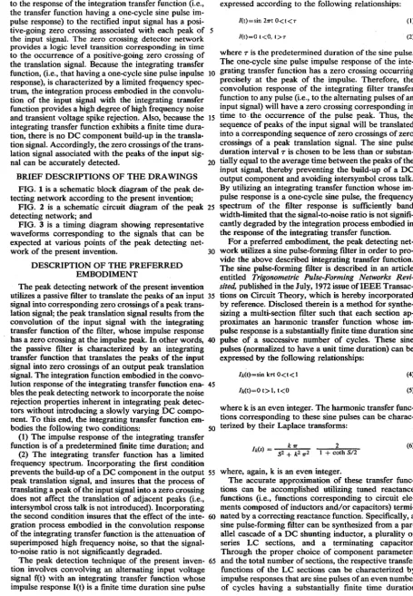
FIG. 1 is a schematic block diagram of the peak de-tecting network according to the present invention;
FIG. 2 is a schematic circuit diagram of the peak 25 detecting network; and
pulse response is a· one-cycle sine pulse, the frequency spectrum of the filter response is sufficiently band width-limited that the signal-to-noise ratio is not signifi-cantly degraded by the integration process embodied in the response of the integrating transfer function.
For a preferred embodiment, the peak detecting net-FIG. 3 is a timing diagram showing representative
waveforms corresponding to the signals that can be expected at various points of the peak detecting net-work of the present invention.
DESCRIPTION OF THE PREFERRED EMBODIMENT
30 work utilizes a sine pulse-forming filter in order to pro-vide the above described integrating transfer function. The sine pulse-forming filter is described in an article entitled Trigonometric Pulse-Forming Networks Revi-sited, published in the July, 1972 issue ofIEEE Transac-tions on Circuit Theory, which is hereby incorporated by reference. Disclosed therein is a method for synthe-sizing a multi-section filter such that each section ap-proximates an harmonic transfer function whose im-pulse response is a substantially finite time duration sine pulse of a successive number of cycles. These sine pulses (normalized to have a unit time duration) can be expressed by the following relationships:
h(t)=sin kTt O<t<1
h(t)=O t> I, t<O
(4)
(5)
The peak detecting network of the present invention utilizes a passive filter to translate the peaks of an input 35 signal into corresponding zero crossings of a peak trans-lation signal; the peak transtrans-lation signal results from the convolution of the input signal with the integrating transfer function of the filter, whose impulse response has a zero crossing at the impulse peak. In other words, 40 the passive filter is characterized by an integrating transfer function that translates the peaks of the input signal into zero crossings of an output peak translation signal. The integration function embodied in the convo-lution response of the integrating transfer function ena- 45 bles the peak detecting network to incorporate the noise rejection properties inherent in integrating peak detec-tors without introducing a slowly varying DC compo-nent. To this end, the integrating transfer function em-bodies the following two conditions:
where k is an even integer. The harmonic transfer func-tions corresponding to these sine pulses can be charac-50 terized by their Laplace transforms:
(1) The impulse response of the integrating transfer function is of a predetermined finite time duration; and (2) The integrating transfer function has a limited frequency spectrum. Incorporating the first condition prevents the build-up of a DC component in the output 55 peak translation signal, and insures that the process of translating a peak ofthe input signal into a zero crossing does not affect the translation of adjacent peaks (Le., intersymbol cross talk is not introduced). Incorporating the second condition insures that the effect of the inte- 60 gration process embodied in the convolution response of the integrating transfer function is the attenuation of superimposed high frequency noise, so that the signal-to-noise ratio is not significantly degraded.
The peak detection technique .of the present inven- 65 tion involves convolving art alternating input voltage signal f(t) with an integrating transfer function whose impulse response I(t) is a finite time duration sine pulse
( k 1T
h $) = 2 2 2
5 + k 1T
(6)
2
1 + coth 5/2
where, again, k is an even integer.
[image:4.617.59.515.63.720.2]6
5
interval T. In particular, the proper choice of a
terminat-ing reactance function (such as terminatterminat-ing capacitor) significantly improves the convergence of the sine pulses to zero, thereby permitting such a sine pulse-forming filter to be formed by a relatively small total 5 number of cascaded LC sections. While the duration interval T is chosen for the preferred embodiment, a
duration of less than T could be incorporated by
appro-priate component selection.
Referring to the schematic block diagram in FIG. 1, 10 a sine pulse forming filter 10 comprises a plurality of sections characterized by transfer functions whose im-pulse responses are finite time duration sine im-pulses of a successive number of cycles. Thus, the inpulse response of a transfer function TF I is a one-cycle sine pulse, the 15 impulse response of a transfer function TF2 is a two-cy-cle sine pulse and the impulse response of a transfer function TF 3 is a three-cycle sine pulse, and so on. An input signal f(t) is applied to the sine pulse-forming filter 10 and the convolution response of the section charac- 20 terized by the integrating transfer function TF I (Le., that having a one-cycle sine pulse impulse response) is tapped to obtain a peak translation signal in which the peaks of the input signal are translated into zero cross-ings. The peak translation signal results from the convo- 25 lution of the input signal f(t) with the integrating trans-fer function TF\, thus corresponding to an integration of the input signal. In order to detect the occurrence of the input signal peaks, the peak translation signal is 30 applied to a zero crossing detector 30 that provides an logic level transition indication for each zero crossing that corresponds to a peak of the input signal f(t).
Lo = 0.5
Lk = 0.25
C _ _ _ 1 _
k - lIk2".2
CT= 0.02047
-continued
(8) (9) (10)
(! I)
where k is an even integer. The value of the terminating capacitor CT is derived by means of the curve fitting techniques disclosed in the article. While other termi-nating reactance functions (such as a termitermi-nating series LC section) can be utilized, specifying a single terminat-ing capacitor results in adequate convergence of the transfer function responses to zero.
The normalized component values can be translated into actual values for a preferred peak detecting net-work as follows. Rl can be arbitrarily chosen subject to the limitations that its value not be so high as increase noise, and not be so low as to make it difficult to drive the sine pulse-forming filter 10. For a perferred embodi-ment, the value of Rl is set at 200 ohms. Once the value of Rl has been specified, the actual component values for the inductors and capacitors of the sine pulse filter 10 are chosen to provide a substantially finite time dura-tion interval (the average duradura-tion between the peaks of the input signal) in accordance with the following rela-tionships:
Tactual Lactua! = Lnormal Tnormal Tactual CaclUai = Cnormai Tnormal
Ractual Rnonnal Ractual
(12) (13)
Referring to the circuit diagram in FIG. 2, sine pulse forming filter 10 includes a parallel cascade of a DC 35
shunt inductor La, four series LC sections, and a termi- where Lnormal and Cnarmal are the normalized values of nating capacitor CT. The DC shunt inductor La shunts inductance and capacitance given by equations 4, 5, 6, any zero frequency component of the input to the filter, and 7; Tactual and Tnormal are, respectively the actual thereby preventing a DC component build-up. The duration interval T and the normalized duration of one
tuned LC sections are formed by, respectively, an in- 40 second; and Ractual and Rnarmal are, respectively, the ductor LI in series with a capacitor CI characterized by actual impedance of 200 ohms and the normalized impe-the transfer function TF\, an inductor L2 in series with dance of one ohm.
a capacitor C2 characterized by the transfer function The number of LC sections in the sine pulse-forming TF2, an inductor L3 in series with the capacitor C3 filter 10 (along with the choice of the value ofterminat-characterized by the transfer function TF3, and an in- 45 ing capacitor Cr) determines the degree to which the ductor L4 in series with a capacitor
<4
characterized by respective responses of the LC sections converge to the transfer function TF4. In accordance with the fore- zero outside the duration interval T. In this context, thegoing discussion of sine pulse-forming filters, the com- total number of LC sections incorporated into sine ponent parameters for sine pulse-forming filter 10 are pulse-forming filter 10 is a matter for design. For the chosen so that the respective transfer functions charac- 50 preferred embodiment, a parallel cascade of four LC terizing the series LC sections have inipulse responses sections is disclosed. Specifying fewer LC sections that are finite time duration sine pulses of, successively, would decrease the convergence to zero of the transfer one, two, three and four cycles, having a duration inter- function responses associated with the remaining LC
val T. sections, while additional LC sections would increase
In order to insure that the series LC sections of sine 55 the converging effect.
pulse-forming filter 10 are characterized by transfer The input signal f(t) is rectified prior to being applied functions that are substantially finite time duration sine to sine pulse forming filter 10. The rectification of the pulses, the value of resistors Rl and the values of each input signal is not essential to the operation of the peak of the inductors and capacitors that form the sine pulse- detecting network, the input signal could be applied forming filter 10 must be carefully chosen. By perform- 60 directly to the sine pulse-forming filter 10. However, ing the analysis disclosed in the hereinbefore referenced the rectification of the input signal f(t) results in an article, it can be established that the normalized compo- output peak translation signal from sine pulse forming-nent values (i.e., the compoforming-nent values that yield trans- filter 10 in which the peaks of the rectified input signal fer functions whose impulse responses are sine pulses of are translated into positive-going zero crossings of the a duration of one second) are designated by the follow- 65 peak translation signal. Accordingly, these zero
cross-ing relationships; ings can be detected by a detector network
incorporat-(7)
recti-7
fying the input signal, or circuitry for detecting both positive- and negative-going zero crossings is a matter for design.
The peak detection network illustrated in FIG. 2 includes a rectification network 20. The input signal f(t) 5 is applied to a phase inverter circuit 22 that outputs separate signals corresponding to the input signal f(t) and its inverse, -f(t). The input signal f(t) and its in-verse are applied to a differential amplifier network 24 that includes transistors Q25 and Q26. The input signal 10 f(t) from the phase inverter is applied to the base of transistor Q25, while its inverse is coupled to the base of transistor Q26. The emitters of transistors Q25 and Q26 are coupled together through a resistor R20 to a nega-tive bias supply - V, while the collectors of the transis- IS tors are connected together and coupled to the sine pulse-forming filter 10.
A conventional phase inverter network can be uti-lized to perform the phase inversion function of phase inverter 22. The foregoing discussion of the differential 20 amplifier pair 24 omits a discussion of the conventional biasing networks that are typically associated with the differential transistor pair Q25 and Q26. . .
The use of a phase inverter 22 together with a differ-ential amplifier 24 provides precise rectification of the 25
input signal f(t). By using such a rectifier network, as opposed to a diode rectifier, nearly perfect rectification is obtained, i.e., the rectified signal is characterized by sharp transistions between the rectified pulses. This type of rectification is important if the amplitude of the 30 input signal f(t) can be approximately the 0.7 forward voltage drop of a diode, or less, with the result that the signal peak would be lost during the process of rectifica-tion.
The input lead signal f(t) is represented by waveform 35 A in FIG. 3; rectification by rectifier network 20 pro-vides a rectified signal fR(t) represented by waveform
B. The rectified signal fR(t) is applied to sine pulse-forming filter 10 across resistor R\. As noted above, the technique embodied in the preferred peak detecting 40 network is to tap the response of the Ll/Cl section of sine pulse forming-filter 10, corresponding to the con-volution of the rectified input signal fR(t) with the inte-grating transfer function TF\ whose impulse response is a one-cycle sine pulse. The response of the transfer 45 function associated with a particular LC section appears at a point between the inductor and the capacitor. Thus, the response of the Ll/Cl section characterized by transfer function TF\ appears at point PI, while the response of the L2/C2 section appears at point P2, the 50 response of the L3/C3 section appears at point P3 and the response of the L4/C4 section appears at P4.
The peak detector network utilizes a buffer transistor Ql to tap the convolution response at point PI without significantly affecting the operation of the sine pulse 55 forming-filter 10. The base of the buffer transistor Ql is coupled to the point. PI while the collector of the tran-sistor is coupled to a negative bias supply - V. The resulting peak translation signal appears on the emitter
other words, the interval between the peaks of the recti-fied input signal fR(t) are translated into corresponding intervals between positive-going zero crossings of the peak translation signal PT(t) appearing on the emitter of buffer transistor Q1. Because the input to the sine pulse-forming filter 10 is a rectified signal, the peak translation signal completes a full cycle between the zero crossings that correspond to the peaks of the rectified input signal
fR(t). If the unrectified input signal f(t) were to be ap-plied directly to sine pulse-forming filter 10, the peak translation signal PT(t) would complete only a single half cycle between the alternating positive-and nega-tive-going peaks of the input signal. Thus, the peaks of the input signal would be characterized by alternating positive-and negative-going zero crossings of the peak translation signal PT(t).
In order to detect the positive-going zero crossings of the peak translation signal PT(t), and thereby recover the sequence of the peaks of the input signal f(t), the peak translation signal appearing on the emitter of buffer transistor Q1 is applied to a positive-going zero crossing detector 30. The results, as represented by a waveform D in FIG. 3, is a peak detection signal PD(t) characterized by positive logic level transitions at the times to, t\, t2 ... ts corresponding to the zero crossings of the peak translation signal PT(t). For the particular detection arrangement indicated in waveform D, the output of the positive-going zero crossing detector ~O
returns to zero at a time corresponding to the negative going zero crossing (between two positive-going zero crossings) of the peak translation signal (wavefore C), in anticipation of the next positive logic level transition associated with the succeeding zero crossing. The posi-tive-going zero crossing detector 30 can comprise any of the conventional positive-going zero crossing detec-tors well known in the art.
The present invention has been described in relation to a preferred peak detecting network that utilizes a sine pulse-forming filter to provide an integrating transfer function whose impulse response is a finite time dura-tion one-cycle sine pulse. An input signal f(t) is applied to the sine pulse-forming filter, and the peak detecting network taps the response of the integrating transfer function to the input read signal. As a result, the peaks of the input signal are translated into zero crossings of a peak translation signal, which can then be detected in a conventional manner. The use of a passive filter to translate the peaks of an input signal into zero crossings avoids the noise susceptibility of differentiating peak detectors and the DC component build-up of integrat-ing peak detectors. Also, the spectrum of the integratintegrat-ing transfer function is sufficiently band width-limited that the high frequency noise content of the input signal can be significantly attentuated by the integration process embodied in the response of the integrating transfer function. In addition, the duration of the one-cycle sine impulse response of the integrating transfer function can be limited in a manner to insure that the detection of a
of buffer transistor Ql. 60 given peak does not affect the detection adjacent peaks.
Referring to FIG. 3, a peak translation signal PT(t) is represented by waveform C. The peak translation signal is an alternating signal characterized by positive-going zero crossings that correspond in time to the peaks of the rectified input signal fR(t). Thus, the peaks of the 65 rectified input signal fR(t) occur at times to, tt, t2 ... ts, while the positive-going zero crossings of the peak translation signal PT(t) occur at these same times. In
While the invention has therefore been described with respect to a preferred embodiment, it is to be clearly understood by those of ordinary skill in the art that the invention is not limited thereto, but rather than the limits of the invention are to be interpreted only in conjunction with the appended claims.
10
9
1. A peak detecting network for indicating the occur-rence of a peak of an alternating current input signal comprising:
integrating filter means, coupled to receive the input signal, for translating the peaks of the input signal 5 into corresponding zero crossings of a translation signal, such zero crossings corresponding in time to the occurrence of the peaks;
said integrating filter means being characterized by an integrating transfer function whose impulse 10 response is a substantially finite time duration sine pulse of one cycle, the predetermined duration of the sine pulse being less than or substantially equal to the average time interval between the peaks of the input signal, with the response of the integrat- 15 ing transfer function to the input signal being said translation signal; and
detector means, response to said translation signal, for providing an indication signal corresponding in time to the occurrence of the zero crossings of the 20 translation signal that corresponds to the peaks of the input signal, and thereby corresponding in time to the occurrence of a peak of the input signal. 2. The peak detecting network defined in claim 1 wherein said indication signal comprises a logic level 25 transition.
3. The peak detecting network dermed in claim 1 wherein said filter means comprises:,
a sine pulse-forming filter, coupled to receive said input signal, comprising a cascade of a plurality of 30 tuned reactance sections characterized by respec-tive transfer functions whose impulse responses are substantially finite time duration sine pulses of a successive number of cycles, including at least a one cycle sine pulse, the predetermined duration of 35 the sine pulses being less than or substantially equal to the average time interval between the peaks of the input signal; and
buffer means for tapping the convolution response of the tuned reactance section having an impulse re- 40 sponse that is a one-cycle sine pulse, said tapped convolution response corresponding to the re-sponse of the associated transfer function to the input signal.
4. The peak detecting network dermed in claim 3 45 wherein said plurality of tuned reactance sections com-prise a parallel cascade of a DC shunt inductor and a plurality of tuned series LC sections each formed by a capacitor in series with an inductor, with the convolu-tion response for reach of said LC secconvolu-tions appearing at 50 a point between the associated capacitor and inductor.
5. The peak detecting network defined in claim 3 wherein said sine pulse-forming filter comprises a paral-lel cascade of a DC shunt indicator; a plurality of tuned
55
60
65
series LC sections each formed by a capacitor in series with an inductor; and a terminating capacitor; the con-volution response for each of said LC sections appear-ing at a point between the associated capacitor and inductor.
6. The peak detecting network dermed in claim 5 wherein said indication signal comprises a logic level transition.
7. The peak detecting network defined in claim 1 further including:
rectifying means for rectifying the input signal such that each peak of the input signal is translated by said integrating filter means into a positive-going zero crossing of the translation signal;
said detector means providing an indication signal corresponding in time to the occurrence of a posi-tive-going zero crossing of the translation signal. 8. The peak detecting network defined in claim 7 wherein said filter means comprises:
a sine pulse-forming filter, coupled to receive said input signal, comprising a cascade of a plurality of tuned reactance sections characterized by respec-tive transfer functions whose impulse responses are substantially rmite time duration sine pulses of a successive number of cycles, including at least a one cycle sine pulse, the predetermined duration of the sine pulses being less than or substantially equal to the average time interval between the peaks of the input signal; and
buffer means for tapping the convolution response of the tuned reactance section having an impulse re-sponse that is a one-cycle sine pulse, said tapped convolution response corresponding to the re-sponse of the associated transfer function to the input signal.
9. The peak detecting network dermed in claim 8 wherein said plurality of tuned reactance sections com-prises a parallel cascade of a DC shunt inductor and a plurality of tuned series LC sections each formed by a capacitor in series with an inductor, with the convolu-tion response for each of said LC secconvolu-tions appearing at a point between the associated capacitor and inductor. 10. The peak detecting network defined in claim 7 wherein said sine pulse-forming filter comprises a paral-lel cascade of a DC shunt inductor: a plurality of tuned series LC sections each formed by a capacitor in series with an inductor; and a terminating capacitor; the con-volution response for each of said LC sections appear-ing at a point between the associated capacitor and inductor.
. 11. The peak detecting network defined in claim 10 wherein said indication signal comprises a logic level transition.