PROGRAMMED BUFFERED DISPLAY 338
Copyright 1967 by Digital Equipment Corporation
Chapter
2.3 2.3.1 2.3.2 2.3.3
Appendix
2
3
PROGRAMMED BUFFERED DISPLAY 338
CON TEN T S (continued)
Display Oriented Computer Instructions •••••.•••••••••••••••••••••
Group 1. From the Display . II. • • • • • • • • • • • • • • • • • • • • • • • • • • • • • • •
Group 2. To the Display ...•
Group 3. lOT Skip on Display Flags ... .
29 29 32 36
VC38 CHARACTER GENERATOR... ... 39
PROGRAMMING EXAMPLES ... . 45
visible, to 111 2, which is very bright. Note that scale and intensity settings are interrelated. For ex-ample, if characters are drawn (with the character generator) at the lowest scale setting, and too high an intensity is used, they will be badly blurred. On the other hand, if many characters are to be displayed simultaneously or if the light pen is to be used, it is best to use as high an intensity level as possible.
1.1.4 State
The display logic is broken into two states, data state and control state. Control state com-mands are interpreted as instructions to the display logic to change parameters, jump, skip, etc. The data state commands are instructions to move the beam via the x and y position registers. When the display is initialized, the commands are accepted in control state until an "enter data state" command is given. The display returns to control state from data state by escaping.
In control state, the first three bits (op code) designate the operation to be performed by the remaining nine bits. Seven of the eight op codes are used:
o
ParameterMode
2 Jump
3 Pop
4 Conditional skip 1
5 Conditional skip 2
6 Miscellaneous (microprogrammed)
o
Arithmetic compare 1Arithmetic compare 2
2 Skip on flags
3 Count
4-7 Set slaves (optional)
7 Sync
The details are discussed in chapter 2 of this manual.
1.1.5 Mode
Data state words are accepted in one of seven formats according to the contents of the mode register. The data state modes available are:
PROGRAMMED BUFFERED DISPLAY 338
0 Point
1 Increment
2 Ve'ctor
3 Vector continue
4 Short vector
5 Character (optiona I)
6 Graphplot
7 Spare
All modes are entered from control state by the Benter data state" command. Each mode, however, has its own way of escaping back to control state. The mode register is cleared by power clear and initialization of the display (lOT 165).
1 .1.6 Subroutining
The display has control state commands which will modify the DAC. This enables unconditional display jumps (jump), jump to subroutine (push jump) and the return from subroutines (pop). The new address is specified by 15 bits allowing direct addressing of 32K of core. The jump and push jump commands are specified by two consecutive 12-bit words. Push jump stores the return address, mode, intensity, scale, and light pen on a push-down pointer list which resides in the first 4K of PDP-8 core. This information is automatically written into two locations in the format shown beloW!
Break Field Light Scale Mode Intensity
Pen
0 1 2 3 4 5 6 7- 8 9 10 11
First Word
Low Order 12-Bits of Memory Address
0 1 2 3 4 5 6 7 8 9 10 11
Second Word
The information is placed in the addresS indicated by the push-down pointer, (PDP) which is a 12-bit register in the display logic. When a push jump is executed, the PDP is incremented twice, adding a new entry to the PDP list. This allows multi-level and recursive subroutines in the display.
1.1.7 Light Pen
The light pen is an input device which generates a signal (flag) that can be sensed and inter-preted by the computer. A light pen interruption stops the display, leaving the contents of all display registers intact, and signals the computer that an interruption has occurred. When this happens, the programmer can examine the contents of the display registers to determine the location (on the display)
of the point of light that was sensed by the light pen and/or determine the memory location of the data word specifying that point. The light pen detects light in the range 4300 to 5600 angstroms.
1.1.8 Pushbuttons
The 338 is equipped with a bank of twelve pushbuttons. They are placed six in a row with a clear button to reset that group. The buttons in each group are interlocked, but two buttons in different groups can be pressed simu Itaneously. Pressing a button complements an associated flip-flop. For reference, the pushbutton is lit when its flip-flop is in the 1 state. The state of the pushbuttons can be sensed both by the display, using the control state skip instructions, and the PDP-S, which can read the state of the push-buttons into the accumulator. The PDP-S and display can also clear and set the pushpush-buttons. This enables three-way communication between the operator, display logic, and PDP-S. The buttons are labeled 0 through 11 and are packaged in a compact, portable box. The box is connected to the display by a 20-ft cable. There is also a special computer interrupt button on the box.
1. 1. 9
There are a number of special conditions that can arise in the display which require the atten-tion of the PDP-S processor. These condiatten-tions are indicated by display flags which can interrupt the computer and be sensed by lOT skip instructions. The flags are:
a. Internal stop b. Ex terna I stop c. Edge
d. Light pen find e. Push button hit
f. Manua I interrupt
PROGRAMMED BUFFERED DISPLAY 338
1 .1 .9.1 Internal Stop - Internal stop is a control state "mode" command (1400S). When the display stops, the DAC has already been incremented and points to the location after the stop code. The PDP-S skips if the internal stop flag is on and lOT 171 is given. lOT 164 with the AC = 0 causes the display to resume from this point.
1.1.9.2 External Stop - The PDP-S lOT 154, with AC bits 0 and 4 at 0, causes the display to stop. When the display stops, the external stop flag is set and interrupts the computer if the interrupt system is on; The time lapse between the lOT and the display stop is dependent upon the display command being executed when lOT 154 is given. The rule is that the entire command will be executed before the display is stopped. If the command is a two-word instruction like jump, pimp, or vector, or point mode command, both words are pulled out of memory and executed before the display stops. The next data word is also transferred to the display and the DAC incremented, but the command is not executed. This allows simple resuming of the sequence even if the display is used in the interim. The external stop flag causes the PDP-8 to skip when lOT 151 is given (with AC bits 0 and 4 at 0). The display sequence can be resumed 'by giving lOT 174, if the display has not been used in the interim.
1 .1 .9.3 Edge - The edge is defined as the point at which the x or y position registers overflow. The initial conditions of the display can be set up so that
all
edges are ignored. In the normal case, the edge flag stops the display; when the edges are ignored, however, the display waits 35 ,",sec and then resumes automatically. The lOT 174 will restart the display from the edge if the display has stopped. lOT 152 causes the PDP-8 to skip if either the horizontal or vertical edge flag is on.If an internal and external stop occur at the same time, only one of the stop flags is set ac-cording to the relative occurrence times.
When an external stop occurs, the fetch cycle for the next display·word is performed, and therefore the DAC remains pointing to the next display word. Execution of lOT 174 will cause the fetched word to be executed first.
1 .1.9.4 Light Pen Find - The light pen find flag always stops the disp.lay as soon as it senses light. This occurs about 3 ,",sec after the initial flash. The display logic therefore has time to execute several more points in the vector before it stops. This must be taken into consideration when reading back the x and y coordinates after the display has stopped. The PDP-8 can skip on the I ight pen flag using lOT 132. The vector or increment sequence can be resumed by giving lOT 174.
pushbuttons into the accumulator. There is no skip lOT for the pushbutton hit flag.
1.1.9.6 Manual Interrupt - The manual interrupt flag is set by the interrupt button on the pushbutton box. It has' a light associated with the flag in the button. Whenever the flag is set, the button is lit. This flag will ~ stop the display. The flag can be cleared by lOT 172, which will also cause the pro-gram counter to skip if the flag is set.
Four of the display flags must be gated onto the interrupt line by the initial condition lOT 145. These flags are edge, light pen find, pushbutton, and internal stop. The external stop and manual inter-rupt flags always cause an interinter-rupt if the interinter-rupt system is on.
1.1.10 Timing
The display can take a break cycle a maximum of one out of four machine cycles. The effective cycle time of the display is 6 fJSec if single cycle instructions are being executed.
*
Allcontrol state instructions except jump, push jump, and pop, are executed in one display cycle. The jump instruction takes two cycles because it is a two-word instruction. The push jump is a four-cycle instruc-tion, two to get the instruction out, and two to push the two status words away on the push down list. The pop instruction is three cycles, one to obtain the instruction and two to pull the status words from the push down list.
In data state, the mode and the number of intensified points determine execution time. In the incremental modes, increment, vector, short vector, and vector continue, points are plotted at a rate of one every 1.1 fJsec for intensified lines and 300 nsecs for non intensified lines. Point and Graphplot mode words are given a 35-fJsec delay to allow the beam to settle, whether the point is intensified or not. If points are plotted in the same general area, as in a continuous curve, the delay for settling is only 6 fJsec. The small delay is given if, and only if, the two points plotted have the same high order 6 bits (of 13) in both x and y position. The time needed to fetch the information must then be added (one or two display cycles) to get the total execution time.
The VC38 Character Generator (optional) plots at about 37 fJsec per character. This time is variable depending on the number of intensified points in the character. Control characters are executed in two display cycles except for carriage return which takes an additional 35 fJsec.
To estimate the time to display a 6-bit character, add up the time required for drawing out the character I then add in 2-1/2 display cycles needed for the character dispatch.
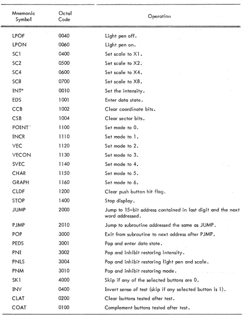
Listed below are the data formats for the control and data state commands. The bit structure, a short general description, and a bit-by-bit explanation are given. The control state also has a list of common mnemonics.
Control state is broken into the seven op codes with the miscellaneous command broken down further to five microprogrammed commands. In data state, each of the seven modes is discussed separately.
2. 1 CONTROL STATE COMMANDS
Control state commands are instructions to the display logic to change a register, such as scale, DAC, mode, etc. Some of the commands change more than one register, so an enable bit is provided for' each function. If the enable bit is a 1, the associated register is reset to the appropriate value. If the enable bit is a 0, the associated re!,]ister is unchanged independent of contents of the bit(s) following the enable ~it. There is no restriction on the number of registers that can be changed with one instruction.
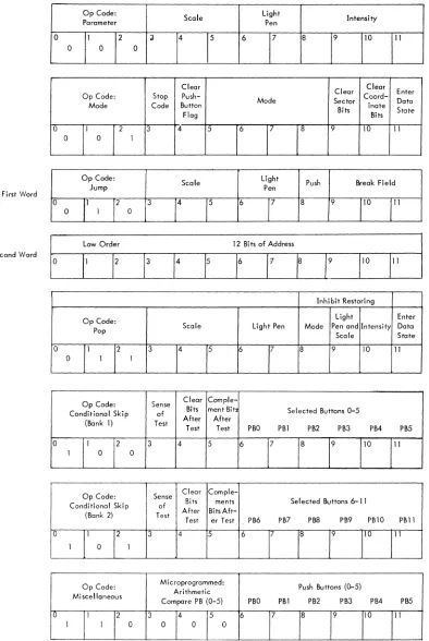
2.1.1 Parameter
Op Code:
Scale Light Intensity
Parameter Pen
0 1 2 3 4 5 6 7 8 9 10 11
0 0 0
Parameter command is an instruction to change the scale, light pen, and intensity registers. When the light pen register is a 1, a light pen hit stops the display. If the light pen register is a 0, all light pen hits are ignored.
Bi t{s}
0-2 3 4,5 6
7
a
9,10,11
Mnemonic Symbol
LPOF LPON SC1 SC2 SC4
sca
PROGRAMMED BUFFERED DISPLAY 338
Op code: parameter Enables scale change.
Interpretation
Determines one of four possible scale settings if bit 3 is a 1. Enables light pen change.
Turns the light pen on when it is a 1, or off when it is 0, provided bit is a 1. Enables intensity change.
Determines one of eight possible intensity settings if bit
a
is a 1.ASSOCIATED MNEMONICS AND VALUES
Octal
Operation Code
0040 Light pen off.
0060 Light pen on.
0400 Set scale to Xl.
0500 Set scale to X2.
0600 Set scale to X4
0700 Set scale to
xa.
INT* 0010 Set the intensity.
*INT only enables the change of intensity; a space then a number between 0 and 7 to indicate the de-sired intensity should follow. Any of the mnemonics of the same op code may be concatenated to form a compound command. A typical parameter command would be:
SC2 LPOF INT 4 which would have an octal value of 554.
2.1.2 Mode
Clear
Clear Clear Enter
Op Code: Stop
Push-Mode Sector Coord- Data
Mode Code Button
Bits inate State
Flag Bits
0 1 2 3
4
5 6 7a
9 10 11The mode command has six separate functions: It can cause the display to stop and set
the internal stop flag, clear push-button, set the mode register, clear sector bits, clear
coordi-nate bits, or enter data state. Only the mode change has an enable bit to prevent its being
changed.
Bits
0,1,2 3
4
5 6,7,8 9
10 11
Mnemonic Symbol
EDS
CCB
CSB
POINT
INCR
VEC
VECON
SVEC
CHAR
GRAPH
CLDF
STOP
Interpretation
Op code: mode.
Stops the display and sets the internal stop flag when bit is 1.
Clears the push-button flag when bit is a 1 .
Enables mode change.
Determines one of eight possible mode settings if bit 5 is a 1.
Clears only the high order three bits in both the x and y position registers when bit is a 1.
Clears only the low order ten bits in the x and y posil'ion registers when bit is a 1.
When bit is 1, the next instruction is accepted as a data state word rather than con-trol state. The display remains in data state until an escape is executed.
ASSOCIATED MNEMONICS AND VALUES
Octal
Operation Code
1001 Enter data state.
1002 Clear coordinate bits.
1004 Clear sector bits.
1100 Set mode to
o.
1110 Set mode to 1 •
1120 Set mode to 2.
1130 Set mode to 3.
1140 Set mode to 4.
1150 Set mode to 5 .
1160 Set mode to 6.
1200 Clear flag.
PROGRAMMED BUFFERED DISPLAY 338
2.1.3
Op Code:
Scale Light Push Break Field
Jump Pen
0 1 2 3 4 5 6 7 8 9 10 11
0 1 0
First Word
Low Order 12 Bi ts of Address
0 1 2 :3 4 5 6 7 8 9 10 11
Second Word
The jump command is a 2-word (24-bit) instruction, 15 bits of which specify the new address. The 15 bits used are the last 3 bits in the first word, which specifies the memory field, and the entire second word, which specifies the address in one of the 4K memory banks. If bit 8 is a 1, the command causes two words to be entered on the end of the PDP list. For full explanation of the push jump command, see "Subroutining section." The jump command can also change the scale and light pen registers.
Bits
0,1,2 3 4,5 6 7
8
9,10,11 Second Word 0,1,11
Op code: jump. Enables scale change.
Interpretation
Determines one of four possible scale settings-if bit 3 is a 1. Enables light pen change.
Turns the light pen on when it is a 1, or off when it is a 0, provided bit 6 is a 1. When bit is a 0, the command is a simple jump, the scale and light pen are changed, and the new 15-bit address is inserted in the DAC and the display continues from there. When bit is a 1, the command is a push jump. The old address and the status of the display are stored on the PDP list; then the new address and scale or light pen change is inserted.
Specifies the high order 3 (of 15) address bits for the jump or push jump command.
Mnemonic Symbol
JUMP
PJMP
LPOF
LPON SCl SC2 SC4 SC8
2.1.4 Pop
Op Code: Pop
0 1
0 1
2 3
1
ASSOCIATED MNEMONICS AND VALUES
4
Octal Code
2000
2010
0040 0060 0400 0500 0600 0700
Scale
5
Light Pen
6 7 8
Operation
Jump to 15-bit address contained in last digit and the next word addressed. Jump to subroutine addressed the same as JUMP.
Light pen off. Light pen on. Set scale to Xl. Set scale to X2. Set sea Ie to X4. Set scale to X8.
Inhibit Restoring
Light Enter
Mode Pen and Intensity Data
Scale State
9 10 11
Bits 0,1,2 3 4,5 6 7 8 9 10 11 Mnemonic Symbol POP PEDS PNI PNLS PNM LPOF LPON SCl SC2 SC4 SC8
PROGRAMMED BUFFERED DI$PLA Y 338
Op code: pop
Enables scale change.
Interpretation
Determines one of four possible scale settings if bit 3 is a 1. Enables light pen change.
Turns the light pen on when it is a 1, or off when it is a 0, provided bit 6 is a 1. The mode status from the PDP list wi II not be restored when bit is a 1.
The light pen and scale status from the PDP list will not be restored when bit is a 1. The intensity status from the PDP list will not be restored when bit is a 1.
The display will be in data state when the word at the address taken from PDP list is executed.
ASSOCIATED MNEMONICS AND VALUES
Octal Code 3000 3001 3002 3004 3010 0040 0060 0400 0500 0600 0700 Operation
Exit from subroutine to next address after P JMP.
Pop and enter data state. Pop and inhibit restoring in-tensity.
Pop and inhibit restoring light pen and sea Ie.
Pop and inhibit restoring mode. Light pen off.
2.1.5 Conditional Skip (Bank 1)
~ ...
Op Code: Sense Clear
Comple-Conditional Skip of Bits ment Bits Selected Buttons 0-5
After After
(Bank 1) Test
Test Test PBO PBl PB2 PB3 PB4 PB5
0 1 2 3 4 5 6 7 8 9 10 11
1 0 0
All display skip commands skip two display words. The display skips twoinstructionsso that a JUMP or P JMP command (which are two words long) can be executed or not executed properly. The buttons to be tested should have 15 in the proper bits of the skip command. UsingJhe" clear and comple-ment facilities, the buttons can be set in any desired configuration. The sense test bit determines whether the user is testing for 1 s or Os.
Bits
0,1,2 3
4
5
6, ,11
Interpretation
Op code: conditional skip (bank 1).
If bit is 0, the display skips two words if any of the indicated push buttons are O. If bit is I, the display skips two words if any of the indicated push buttons are 1. Sets all the selected push buttons to the 0 state (light off) when it is "a I, inde-pendent of the outcome of the test.
Complements all the selected push buttons after the test when it is a I, independent of the outcome of the test. Since the buttons are cleared before they are comple-mented, they can be set to the 1 state by having both bits 4 and 5 at 1.
. -~
Selected push buttons of bank 1 i e.g., bit 6 = push button 0, bit 11 = push button 5.
2.1.6
Mnemonic Symbol
SK1
INV
CLAT
COAT
PROGRAMMED BUFFERED DISPLAY 338
ASSOCIATED MNEMONICS AND VALUES
Octal Value
4000
0400
0200 0100
Operation
Skip if any of the selec.ted
but-tons are O.
II,vert sense of test (skip if on)'
selected button is 1).
Clear buttons tested after tes,.
Complement buttons tested after test.
----.-~---'----... ---. . . -.-.----'--~---... Conditional Skip (B:lnk 2)
r
,
-rr--._-... _-.-.-....
Op Code: Sense Clear
Comple-CondiHonal Skip Bits ments Sel ect<;;d Buttons 6-] '1
I
of
After BitsAft- ... .
(Bank 2) Test
Test er Test PB6 PB7 PBS PB9 PBlO
0 1 .
2 3 4 5 6 7
J
1 0 1
L
11O-,T1'
"
I
'
___ . ______ L. ___ ._;
. This command is identical to conditional skip (bank 1) except that it tests push button, (,.' : .
Bits . Interpretation
====I==========================·.=.=-:::cc·-: ..
0,1,2
3
4 5 6-11
Op code: conditional skip (bank 2).
Same as conditional skip (bank 2).
ASSOCIATED MNEMONICS AND VALUES
Mnemonic Symbol
SK2
INV
CLAT COAT
2.1.7 Miscellaneous
Octal Value
5000
0400
0200 0100
2.1.7.1 Arithmetic Compare Push Buttons (Bank 1)
Op Code: Microprogrammed:
Arithmetic Mi scellaneous
Compare PB (0-5)
0 1 2 3 4 5
1 1 0 0 0 0
PBO PBl
6 7
Operation
Skip if any of the selected but-tons are O.
Invert sense of test (skip if any of the selected buttons are 1). C lear buttons tested after test. Complement buttons tested after test.
Push Buttons (0-5)
PB2 PB3 PM PBS
8 9 10 11
Bits 6-11 of this command are compared to the contents of buttons 0-5 (bank 1). If all the bits and buttons match, the test succeeds and the display follows a normal sequence. If the test fails, the display skips two words.
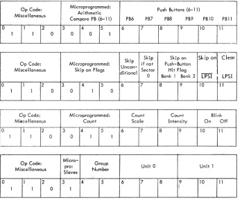
2.1.7.2 Arithmetic Compare Push Buttons (Bank 2)
Op Code: Microprogrammed: Push Buttons (6- 11)
Arithmetic Miscellaneous
Compare PB (6-11) PB6 PB7 PB8 PB9 PB10 PBll
0 1 2 3 4 5 6 7 8 9 10 11
1 1 0 0 0 1
PROGRAMMED BUFFERED DISPLAY 338
2.1.7.3 Skip on Flags
Skip Skip Skip on Skip on Clear
Op Code: Microprogrammed: if not Push-Button
Miscellaneous Skip on Flags Uncon- Sector Hit Flag
ditional
--0 Bank 1 Bank 2 LPSI LPSI
0 1 2 3
.4
5 6 7 8 9 10 111 1 0 0 1 0
All the commands will skip two words if the test fails. Sector 0 is defined as any point where
the x and y position registers have a II Os in the high order 3 bits (of 13). The push button hit skip skips
on the individual banks (1 or 2). Both flags are cleared by lOT 062 or by the display command CLDF
(12008), The light pen sense indicatoris set whenever the light pen senses light, whether the light pen is enabled or not. If both bit 10 and bit 11 are on, the logic first tests then clears the LPSI.
The light pen sense indicator (LPSI) is a special light pen flag which is set whenever the light
pen senses light. This action is independent of the status of the light pen enable flag. Bits 10 and 11
control testing and clearing of the LPSI. When bot!' bits are 1, the sense of the skip is determined before
the LPSI is cleared. The LPSI cannot be cleared O~ ~es~ed by the PDP-So
Bi t(s) Interpretation
0,1,2 Op code: miscellaneous.
3,4,5 Microprogrammed: skip on flags.
6 Do not execute the next two display words if bit is 1 .
7 Do not execute the next two words unless the high order three bits of both the x and y position registers are 0; i.e., skip if the beam is not on the screen.
8 Skip if any push button 0-5 has not been pushed.
9 Sk i P if any pus hbutton 6- 11 has not been pus hed .
10 Skip if the light pen sense indicator is O.
11 Clear light pen sense indicator flag.
2. 1 .7.4 Count
Op Code: Mi croprogrammed: Count Count Blink
Miscellaneous Count Scale Intensity On Off
0 1 2 3 4 5 6 7 8 9 10 11
The scale and intensity registers are also up-down counters. They cannot overflow; however, the scale register stays at 112 no matter how many count scale up commands are given. The blink facility allows the picture or any section of it to flash on and off at 1 cps (1/2 sec wtth the intensity on a~d 1/2 sec with the intensity off) .
Bit(s) Interpretation
0,1,2 Op code: miscellaneous.
3,4,5 Microprogrammed: count.
6 Enables count scale logic.
7 0: count sca Ie up (unless at 112)'
1: count scale down (unless at 002),
8 Enables count intensity
logic.-9 0: count intensity up (unless at 1112),
1: count intensity down (unless at 0002),
10 Turn blink on, all intensified points will be gated through the blink logic.
11 Turn blink off.
2.1.7.5 Slave Logic (Optional)
Op Code: Micro- Group
pro: Unit 0 Unit 1
Miscellaneous
Slaves Number
0 1 2 3 4 5 6 7 8 9 10 11
1 1 0 1
PROGRAMMED BUFFERED DISPLAY 338
Bit(s) Interpretation
0,1,2 Op code: miscellaneous.
3 Specifies slave logic when it is a 1.
4,5 Choose one of four slave groups, with two units each, to be modified.
*
6 Enables change of unit 0 of slave group specified in bits 4,5.
7 Turns on light pen of unit 0 if bit is a 1; turns it off if bit is a O. 8 Turns on the intensity of unit 0 if bit is a 1; turns it off if bit is a O.
9 Enables change of un it 1 of slave group specified in bits 4,5.
10 Turns on light pen of unit 1 if bit is a 1; turns it off if bit is a O. 11 Turns on the intensity of unit 1 if bit is a 1; turns it off if bit is a O.
2.1.8 AC Synchronization Control
-!
'I' Op Code: , Spares
Skip on IDLE FLAG
ro - -- --
[A~
syn1
2j'-.---
" - " .-------10
I 1 1, 1
L_ -______
1_______
_
__ ..
-- --- i .---.-~--.,,--•.. _-.. _ - , -->---Clear IDLE _ FLAG ; 11
The AC synchronization control command may be used to eliminate the often observed "swimming'
of information on the screen, due to local electromagnetic fields. The oufput of the cathode ray tube is
synchronized with the input line voltage.
To use this synchronizing feature, the following code may be inserted at anyone point in the
display file:
Example: Insert at loc 1500
1500: 7001
7002 2000 1501
/clear idle flag /skip on idle flag /jump to
/1501
---r---• BU, ..
+ .
Intecpeetation0-2 Op Code: AC sync
3-9
10
11
Spare
Skip on IDLE FLAG
Clear IDLE FLAG
Mnemonic Symbol SK3 SK4 SKIP SNSZ SPBl SPB2 SLPSI CLPSI SCUP SCD~ INTUP INTDN BKON BKOF SGO SGl SG2 SG3 SUO LPO ITO SUl LPl ITl Octal Value 6000 6100 6240 6220 6210 6204 6202 6201 6340 6360 6310 6314 6302 6301 6400 6500 6600 6700 0040 0060 0050 0004 0006 0005 Operation
Arithmetically compare pushbuftons (0-5) with last two digits of instruc-tion; skip if not equal.
Same as SK3 but for buttons 6-11 .
Unconditional skip (two locations).
Skip if sector 0 flag is not up.
Skip if push button (0-5) flag is down.
Skip if push button (6-11) flag is down.
Skip if LPSI is off.
Clear LPSI.
Count scale up.
Count scale down.
Count intensity up.
Count intensity down.
Blink on.
Blink off.
Set slave group O.
Set slave group 1". Set slave group 2.
Set slave group 3.
Turn light pen and intensity off on unit O. Unit 0 light pen on.
Unit 0 intensity ·on.
Turn light pen and intensity off on unit 1.
Unit 1 I ight pen on.
Unit 1 intensity on.
2.2 DATA STATE COMMANDS
All data state commands change the x and y position registers which are in turn connected
through D to A converters to the CRT deflection system. The mode register determines the data state
PROGRAMMED BUFFERED DISPLAY 338
the eight possible modes are used. If the display tries to enter data state in the unused mode, (111 2),
the display stops but no error flag is raised. Each of the seven modes has an escape mechanism to return
to control state. Since most of the modes are different, each is described below.
Point, vector, and vector continue modes are two-word commands; a single command is
specified by two consecutive locations in the display list. Both words must be brought out before
ex-ecution, and therefore there are two input buffer registers. The register DX, which is used for all
com-mands, receives its information directly fr-:-m the data lines. If ~he command is two words long, the first
input word is transferred to the DY register while the second input word is brought in to DX from memory.
The only exception to this is data state increment mode words. In this case a single word command is
executed from the DY register. The DX register is used for double buffering virtually eliminating the
wait for input words. Short vector mode uses the DY register in order to appear as a normal vector. In
other words, the delta Y portion of the comm'md is transferred to the DY register.
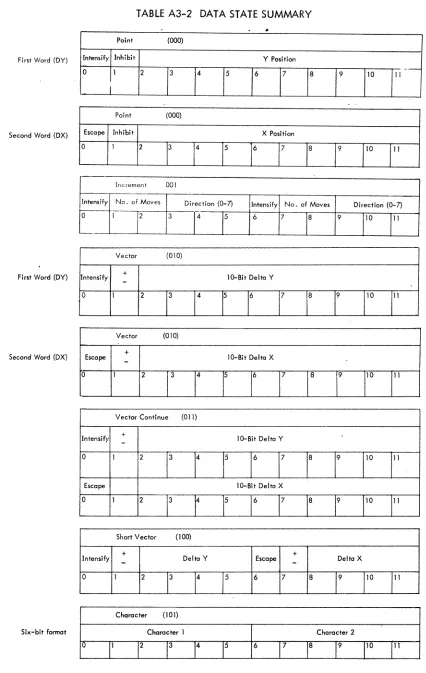
2.2.1 Point Mode (Two Words)
Point (000)
Intensify Inhibit Y Position
0 1 2 3 4 5 6 7 8 9 10 11
First Word (DY)
Point (000)
Escape Inhibit X Position
0 1 2 3 4 5 6 7 8 . 9 10 11
-I.
Second Word (DX)
The basic action is to jam bits 2 through 11 of the first word (from DY) into the low order ten
bits of the y position register, and the same bits in the second word into the x position register. The high
order three bits in x and y remain unchanged. If bit 1 in either word is up, the contents of the associated
position register are not changed during that command . This is usefu I if the user does not know the present
beam position and wishes to change either x or y and leave the other at the same va lue. If bit 0 in the
first y point word is a 1, the point specified is intensified when the beam reaches the proper position. If
bit 0 in the second word (x point) is a 1, it indicates an escape and the next word is interpreted as a
2
2.2.2
Intens ify
0
o
If bit is a 1, intensity given point.2-11
o
Inhibit changing y position register.
New y coordinate (low order ten bits).
Escape to control state.
Inhibit changing x position register.
2-11 New x coordinate (low order ten bits).
Increment Mode
Increment 001
No. of Moves
I
Direction (0-7j-
I
Intensify No. of Moves
1 2 3 4 5 6 7 8
Direction (0-7)
9 10 11
Increment mode is a mechanism for moving the beam a short distance in an efficient manner.
The beam is moved from its previous position to a new position according to a 6-bit increment byte. Each
byte is handled separately and executed independently of the other. Both bytes (first, 0-5, second, 6-11)
are identical; therefore only the first will be discussed.
The byte is broken into three sections: first, to indicate whether the byte move is to be
in-tensified (bit 0 (6)); second, to give the number of moves to be made (bits 1, 2 (7, 8)); and third, to specify the direction in which the move is to be made (bits 3, 4, 5 (9, 10, 11)). The beam is only in-tensified at discrete points according to the scale setting (see IIScalell section 1. 1.2), it is not run with
the beam on during the motion. The increment can consist of one, two, or three moves per byte, with
each move being one, two, four, or eight points apart on the raster depending on the scale. The two
bits that control the number of moves are programmed as follows:
Bits 1,2
00
01
10
11
Interpretation
Move the beam once in the indicated direction and escape.
Move the beam once; do not escape.
Move beam twice; do not escape.
PROGRAMMED BUFFERED DISPLAY 338
The three bits for direction indicate one of eight 45 degree directions:
2
3
~1
1.~.:/.
4 ( 0 ~ Starting Position
5/r~7
6
The letter "A" is programmed in subroutine form as an illustration of the use of increment mode.
0 0 0
0 0
0 0
0 0
0 0 0 0 0
0 x 0
E~final
starting ~ 0 x
o
xpoint x x x point
The ",0" indicates an intensified point, the "Xll a nonintensified point, and IIEII the point at which the escape is given.
ALPHAA,
Bit(s)
o
1,2 3,4,5 6 7,8 9,10,11
INCR 1672 7251
6057
7674 3762 2701 POP
EDS /octal (1111)
/byte 1 -oJ, ,1m, noninten. byte 2 -I} ,3m, inten. /byte 1
-1'
,3m, inten. byte 2 -11
,1m, inten. /byte 1 - ~ ,2m, inten. byte 2 - ~, 1 m, inten. /byte 1-..v
,3m, inten. byte 2 - ~, 3.m, inten. /byte 1 - ~, 3 m, noninten. byte 2-1, 2 m, inten.
/byte 1 -'~, 2 m, noninten. byte 2 -jf ,1m, noninten. and escape /octal (3000)
.In terpretati on
If bit is a 1, intensify the first byte.
Number of moves in the byte (002:::!;> Move once and escape) . Direction in wh ich moves are to be made.
I
Vector (OlO)
Intensify +
-
10-Bit Delta Y0 1 2 3 4 5 6 7 8 9 10 11
First Word (DY)
Vector (OlO)
+ Escape
-
10-Bit Delta X0 1 2 3 4 5 6 7 8 9 10 11
Second Word (DX)
Vector mode is used to draw long straight lines. The beam is moved from its present location in the direction and distance specified by the delta y and delta x. The deltas tell the beam how many moves to make in x and y before stopping. The number of raster points between each move is again de-pendent upon the contents of the scale register. At a scale of one, the lO-bit vector can take the beam from one end of the screen to the other. At a scale of eight, the beam can go to any point on the 13-bit
II paper . II Bit 1 in both words indicates the sign (direction) of the vector. A + is indicated by a 0 and is
up for y and to the right for x. Bit 0 in the first word indicates whether the vector is to be intensified. Bit 0 in the second word is the escape to control state which indicates the end of a vector string.
The following display subroutine program places on the screen a 1-inch square. Since the box is drawn with vectors, it can be put anywhere on the screen (relocatable).
Direction of Beam Movement
Starting and final point
IBOX, SC2 INT 5
VEC EDS 4067 0000 4000 0067 6067 0000 4000 6067 POP
/Control state octal (515) /Control state octal (1121) / tJ.y = +55. intensify
/tlx = O.
/ tJ.y = O. intensify /6.x = +55.
/ tJ.y = -55. intensify
/tJ.x= O.
Word
2
2.2.4
..
Intensify
0 1
Escape
0 1
PROGRAMMED BUFFERED DISPLAY 338
Bits Interpretation
o
If bit is a 1, intensify the vector.1 If bit is a 0, the sign of delta y given in bits 2-11 is positive; if a 1, it is negative.
2-1
J
The lO-bit delta y.o
If bit is a 1, the next word is interpreted in control state.If bit is a 0, the sign of delta x given in bits 2-11 is positive, if a 1, it is negative.
2-11 The lO-bit delta x.
Vector Continue Mode (Two Words)
Vector Continue (011)
.+
10-Bit Delta Y
-2 3 4 5 6 7 8 9 10 11
' '.
lO-Bit Delta X
2 3 4 5 6 7 8 9 10 11
Vector continue mode has the same format and action as vector mode, except the vector does not stop until it violates the edge. This will not cause an edge flag to be set..
. 2.2.5
Short VectorShort Vector (100)
+
+
Intensify
-
Delta Y Escape-
Delta XShort vector mode is basically the same as vector mode except it is only one word long. In order to fit it into one word, the maximum number of increments has been reduced from 1,024 to 16 in x and y directions. Bits
°
and 1 of a short vector word correspond to bits°
and 1 of the first word of a vector command. Bits 2, 3, 4, and 5 correspond to 8, 9, 10, and 11 of the first word; bits 6 and 7 to bits°
and 1 of the second word; and bits 8, 9, 10, and 11 to bits 8, 9, 10, and 11 of the second word. In execution of a short vector mode command, the left half of the input word is transferred to DY and bits are rearranged to be in the same format as a vector mode command.Bits
°
2,3,4,5 6 7
8,9,10,11
Interpretation
If bit is a 1, intensify the vector.
If bit is a 0, the sign of delta y in bits 2, 3, 4, and 5 is positive; if a 1, it is negative.
The 4-bit delta y.
If bit is a 1, the next word is interpreted in control state.
If bit is a 0, the sign of delta x given in bits 8, 9, 10, and 11 is positive; if a 1, it is negative.
The 4-bit delta x.
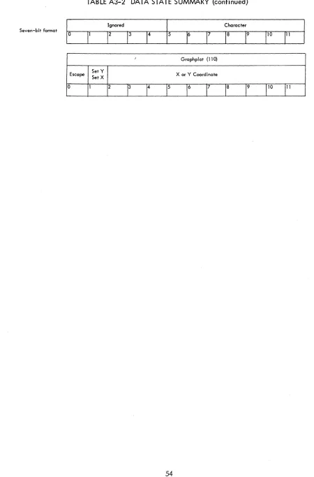
2.2.6 Character Mode (Optional)
Character (101)
Character 1 Character 2
°
11 1213 14 15
6
17
18 19 11o
III
Six-bit format
Ignored Character
PROGRAMMED BUFFERED DISPLAY 338
The character generator can be run in two different formats: 6-bit format, packed two to a
word but directly referencing only 64 characters, or 7-bit format, only one character per word but referencing 128 different characters. The character generator is simply an efficient dispatch system for instructions stored in core memory. The characters, therefore, are programmable as well as the dispatch table that calls them. The details of programming the character generator are given in appendix 1.
Special characters available in the character generator include set and count intensity and scale, set light pen, change case, change character set, change code size (6-bit versus 7-bit), carriage return
(clear x register), and escape to control state.
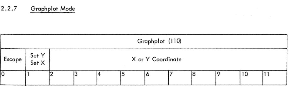
2.2.7 Graphplot Mode
Graphplot (110)
Escape Set Y X or Y Coordinate
Set X
0 1 2
13 14 15 16 17 18 19
1
10111
Graphplot mode is a concise way of describing and displaying tabular data. The execution of a data command is as follows: First, the x or y coordinate is incremented once; then the other coordinate is set by bits 2-11 of the graphplot mode command. Bit 1 of the word specifies whether x is to be in-cremented and y plotted (bit 1-0), or y incremented and x plotted (bit 1-l). If bit 0 is a 1, the display escapes to control state.
The incremented axis moves one, two, four, or eight points depending on the scale setting. Since one axis is always incremented, the graph is easily translated in this direction by changing the starting location.
Bit(s)
o
2-11
Interpretation
If bit is a 1, escape to control state.
If bit is a 0, increment x coordinate and set the y coordinate with bits 2-11; if bit is a 1, increment y and set x.
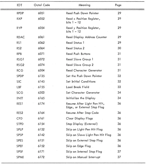
[image:31.612.63.554.230.381.2]2.3 DISPLAY ORIENTED COMPUTER INSTRUCTIONS
The PDP-8 has a family of instructions
*
which it uses to communicate with I/O equipment. A group of these instructions is assigned to the display (lOTs 05,06, 07, 13, 14, 15, 16, 17, 30). Givenbelow are the display lOTs, their mnemonics, and their functions. They are broken into three classes:
the first requests information from the display; the second sends information to the display; and the third
class is the computer skip on display flags. The information transfer is done through the PDP-8
accumu-lator; so if the user expects information, he should clear the AC beforehand, and if sending information,
he should have the data in the AC before giving the lOT.
2.3.1 Group 1. From the Display
2.3.1.1 RPDP 6051 Read Push Down Pointer - A 1s (inclusive OR) transfer from the push down pointer (12 bits) to the AC is done. The PDP should be pointing to the location in which status information will
go on the next push jump (if it comes before a pop). Reading the PDP, subtracting the set value, and
dividing by two gives the level of the subroutine.
2.3. 1 .2 RXP 6052 Read x Position Register - A 1s transfer from the x position register to the AC is done.
Only the low order 12 (of 13) bits are transferred; the high order bit must be obtained from the RS2
instruction.
2.3.1.3 RYP 6054 Read y Position Register - Same as RXP, except the y position register is transferred,.
2.3. 1.4 RDAC 6061 Read Display Address Counter - The contents of the display address counter are
transferred from the display to the AC. The DAC will be set at the next command to be executed by the
display.
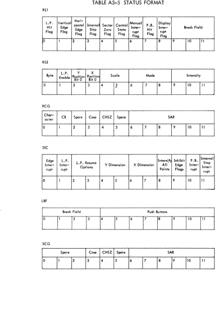
2.3. 1 .5 RS 1 6062 Read Status 1 - Status 1 consists of the state of all display flags and the contents of
the break field register. If the flag is up the associated bit· is a 1. After the lOT is given the pushbutton
flag will be cleared. The lOT reads back the old state of the flag into AC bit 7.
RSI
L.P. Vertical zontal Internal Sector Control Hari- Manual P.B. Display Hit Edge
Edge Stop Zero Stote Inter- Hit Inter- Break Field Flag Flag
Flag Flag Flag Flag rupt Flag rupt Flag Flag
1°
1
2 3 4 5 6 7 8 9110
111
o
2 3 4
5
6 7 8
Bi t{s)
9,10,11
PROGRAMMED BUFFERED DISPLAY 338
Interpretation
light pen hit flag.
Vertical edge flag. The y position register has overflowed.
Horizontal edge flag. The x position register has overflowed.
Interna I stop flag.
Sector 0 flag. If bit is a I, the display is in sector O.
Control state flag. If bit is a I, the display is in control state, if it is a 0 the display is in data state.
Manua I interrupt flag.
Push-button hit flag.
Display interrupt flag. If the interrupt system is turned on and bit is a I, the com-puter will interrupt. It is set by one of the six display flags being on and gated onto the'interrupt line.
Contents of break field register. These three bits and the twelve bits from the RDAC instruction give the full 15-bit memory address.
2.3.1.6 RS2 6064 Read Status 2 - Status 2 consists of the contents of some of the major registers in the
display; e.g., light pen scale, mode, and intensity. It also contains byte information and the high order
bit of the x and y position registers. The byte flip-flop indicates whether the left half or right half byte
in increment mode was being executed when the display stopped. It does not tell whether the right or
left hand character is being executed; this information is obtained from the RCG (JOT 304) instruction.
The low order twelve bits of the 13-bit x and y position register are obtained by giving RXP or RYP.
RS2
Byte L.P. y X
Enable Position Position Scale Mode Intensity Bit 0 Bit 0
0 1 2 3 4
I?
617
1
8
9
1
o
2 3
Bi t(s)
4,5
6,7,8
9,10,11
Interpretation
Byte flip-flop. If bit is a 0, the left hand increment is being executed; if bit is aI, the right hand byte is being executed.
light pen enable. If bit is aI, the light pen is enabled.
High order y position register bit.
High order x position register bit.
Scale
Mode
Intensity
2.3.1.7 RPB 6071 Read Push Buttons - The contents of the twelve push buttons (0-11) are transferred
into the corresponding AC bits.
2.3.1.8 .RSGI 6072 Read Slave Group 1 - On this instruction, the light pen enable, light pen hit, and
intensity status for slaves 0, 1,2, and 3 are read into the AC. The control state command "set slaves" sets the light pen and intensity status. If the slave option is not present, the lOT reads back Os into the
ac-cumulator.
Slave 0
Light
Intensity Pen
0 1
AC Format
Bi t(s)
o
2
3,4,5
6,7,8
9,10,11
Slave 1
light Pen Hit
2 3 4 5
light pen enable, slave O.
Intensity status of slave O.
6
Interpretation
light pen hit, status slave O.
Same format as above for slave 1 •
Same format as above for slave 2.
Same format as above for slave 3.
Slave 2 Slave 3
PROGRAMMED BUFFERED DISPLAY 338
2.3.1.9 RSG2 6074 Read Slave Group 2~ RSG2 has the Same format as RSG1, except it reads status of slav,es 4,5,6, and..7 •
2.3.1.10 RCG 6304 Read Character Generator ~ RCG readsin the five character generator parameters: character generator active (CHACT), character byte (CB), case, code size (CHSZ), and starting address register (SAR). The CHACT bit indicates whether the' character generator is in use; i.e., the display is
in character mode and data state. The CB shows whether the left or dght half character (6~bit format) is being executed. The case bit is used (6~bit format) asa seventh bit to allow referencing either the lower or upper set of 64 characters. The CHSZ indicates whether the 6~bit or 7~bit character format is to be used. The SAR is a 6~bit register that indicates the starting address of the character dispatch table (see appendix) •
0
Chor-CB acter
1 2
Bi t(s)
o
Spare Case CHSZ Spare
3 4 5 6 7
Interpretation
If bit is aI, the character generator is active. If bit is a 0, left character is being executed. If bit is aI, right character is being executed.
2 Spare.
8
3 If bit is aI, upper case is in use, characters 65~ 128.
SAR
9 10 11
4 If bit is a 0, the character generator is using 6-bit format; if bit is aI, the CG is using 7-bit format.
5 Spare.
6-11 Contents of the 6-bit SAR.
2.3.2 Group 2. To the Display
instruction enables four display flags onto the interrupt line, sets the paper size to 10, 11, 12, or 13 bits in x and y and light pen conditions. There are three options in the event the display is resumed after a light pen hit. The light pen can be left on, it can be turned off completely, or it can be turned off un-til the completion of the present command, then automatically turned back on at the next data request. There is also a register that tells the display to ignore all edge flags; therefore when the position register overflows, the edge flag is inhibited and the display continues in a normal fashion. Another register overrides the intensification bit in data state, causing all beam movements to be intensified. This feature is used principally for diagnostic purposes.
Bit(s)
o
2
3
4,5
6,7 8 9
10 11
SIC
Intensi.f> Inhibit P.B. Internal Edge loP. Stop
Inter- loP. Resume Y Dimension X Dimension All Edge
Inter-Options
Inter-0
rupt rupt
1 2 13
4
15
617
Interpretation
Enable edge flag interrupt. Enable light pen flag interrupt.
Points Flags rupt rupt
8 9 10 11
If bit is a 0, do not disable light pen after the resume; if bit is a 1, bit 3 indicates when to reenable the light pen.
If bit is a 0, reenable light pen on the first data request after the display is resumed. If bit is a 1, the light pen hit is equivalent to a LPOF command.
Set Y dimension.
00: 9.375 inches (10 bits) 01: 18.75 inches (11 bits) 10: 37.5 inches (12 bits) 11: 75.0 inches (13 bits) Set X dimension, same as Y. Intensify all points.
Inhibit edge flags.
PROGRAMMED BUFFERED DISPLAY 338
PART 1
SYSTEM INTRODUCTION
The Type 338 Programmed Buffered Display is a precision incrementol display system, consisting
of a small scale, high speed computer and a display subsystem for control of the CRT. The computer used
is the Digital Equipment PDP-8 (for Programmed Data Processor). It is a single address, fixed word length
(twelve bits) machine. The complete cycle time for its random access magnetic core memory is 1 .5!-,sec. All arithmetic operations are performed in 25 complement notation.
This guide enables the experienced user to adapt the powerful capabilities of the Type 338 to
his application. The contents assume that the reader is familiar with the operation of the PDP-8 and its instruction set. This information is readily available in the PDP-8 User Handbook, F-85.
1.1 FUNCTIONAL DESCRIPTION
A ,self-contained unit with built-in control and power provisions, the 338 Display may be
inter-faced to an existing system or it may stand alone as a powerful computer-driven display system. The CRT
is a 16-inch tube with 9-3/8 inch by 9-3/8 inch usable display area. Magnetic deflection and focusing
techniques result in uniform resolution over this area. Up to eight display CRTs may be remotely slaved to the 338 Display. All can receive identical information, or all can receive different information, or any combination can be established. The routing of information to the slave display is a function of display file instructions in the control state.
The display logic can be thought of as a special purpose computer which stores its instructions
(display commands) in the memory of the PDP-8, and interacts with the computer through a series of
in-struction interrupts and data transfers. The display is an output device with respect to the computer for the following reasons:
a. The PDP-8 has a series of instructions which start, stop, and load and interrogate the registers of the display.
b. The PDP-8 can modify the data commands which are interpreted by the display be-cause the commands are stored in the PDP-8 memory.
The commands are transferred to the display control via the PDP-8 single cycle data break
sys-tem. The display file words are loaded into a table or block of successive memory locations; and the
begin-ning location of this table is loaded into a special register called the display address counter (DAC). The
output of the DAC and the break field registers are appl ied to the inputs of the memory (MA) register
form-ing a 15-bit address which can increment across memory field boundries. The data break is then
goes through a break cycle in which it fetches the word from memory and places it ,into its memory buffer (MB) register from where it is transferred to the buffer register (DX) in the display. During this time, the display starts its operation and the DAC is incremented by one. The computer program counter (PC) is not incremented during the break cycle. At the end of the break cycle the PDP-8 continues its main pro-gram unti I the display requ ires another data break.
1 • 1 • 1 Display Parameters (Coordinate System)
The display screen which is 9-3/8 inches square, has 10 bits of resolution; in other words there are 1,024 points in the x and y directions or about a million points in all. The x and y position registers are 13 bits long, however I and therefore the screen represents only 1/64 the total addressable area (paper).
The paper is broken up into 64 sectors corresponding to the upper 3 bits of x and y, with sector 0 defined as the lower left sector. Only information in sector 0 is intensified so that translation is accomplished by moving the paper in relation to sector O. The lower left corner is point (O,O), and the coordinates in-crease to the right and up, and dein-crease to the left and down. An edge violation occurs when a line is drawn across the boundary of the paper. This is a warning that an overflow condition has just occurred in the x or y position register. A vertical edge flag indicates the y position register went from all Is to all Os, or from all Os to all Is. The horizontal edge flag indicates overflow in the x register. The over-flow can be set to occur after the 10th, 11 th, 12th or 13th bit in x and y. The virtua I paper size can therefore be changed under program control.
1.1.2 Scale
The scale setting determines the number of positions each succeeding spot is moved before it is intensified. It effects both the size and appearance of lines or symbols drawn in the vector, vector continue, short vector, increment, or character modes. At scale setting 11 2, each point can be clearly distinguished. At scale setting 002, lines and symbols appear to be continuous. The point spacing is illus-trated in the following table.
Scale Point Spacing Intensify
002
•
• •
• • •
•
•
• •
Every01 2
•
a
•
a
•
a
•
a
•
a
2nd102
•
a a a
•
a a a
•
a
4thPROGRAMMED BUFFERED DISPLAY 338
2.3.2.3 LBF 6155 Load Break Field - This instruction has two functions. First, it loads the break field register when initializing the display; second, it sets the push buttons. ~oth functions have enable bits so that one may be executed without the other •. If neither enable bit is up, both lOT pulses have other meanings (STPD-6154 and SPES-6151).
0
Break Field Push Buttons
1 2 3 4 5 6 7 8 9 10
Bit(s) Interpretation
o
Enable change of break field.1,2,3 New break field.
4 Enable change of push buttons.
5 If bit is a 0, set push buttons 0-5 according to AC bits 6-11; if bit is a 1, set pl,lsh buttons 6-11 according to AC bits 6-11 .
6-11 New push-button states.
11
2.3.2.4 SCG 6303 Set Character Generator - SCG sets the SAR case and CHSZ.
Spare Case CHSZ Spare SAR
0 1 2 3 4 5 6 7 8 9 10 11
Bit{s) Interpretation
0,1,2 Spare.
3 Set case O-Iower 64.
1-upper 64.
4 Set code size 0-6 bit character format.
1-7 bit character format.
5 Spare.
the low order twelve bits of the DAC, cmd the display is initialized by raising the break request flag. The
display will run uninterrupted until a flag is raised.
INIT must not be executed when the display is running since it ignores the timing and causes
random errors. If an external stop is used to stop. the display before executing INIT, the display stopping
time is dependent on execution of the display command, and INIT should not be executed unti I the ex-ternal stop flag goes on.
The five lOTs given (2.3.2.1-2.3.2.5) comprise a standard startup procedure for the display.
The following program isgiven os qn example.
Initial,
XPDP,
XSIC,
XLBF,
/Display start-up routine for
/338 with VC38 Character Generator.
CLA
TAD XPDP
SPDP
CLA
TAD XSIC
SIC CLA
TAD XLBF
LBF
CLA
TAD XCG
SCG
CLA
TAD XIN
INIT
CLA
'ION
JMP .
7000
2367
4000
,/Clear AC.
/Starting address for PDP, into AC .
/IOT to transfer AC to PDP.
/ClearAC.
!Constant to set initial conditions.
/Transfer AC to init.ial condition register.
/Clear AC.
/Constant for BF and/or PB.
/Transfer AC to BF.
/Clear AC.
/Constant for character generator.
IIOT to transfer AC to C G . /Clear AC.
/12-bit starting address for display.
/IOTto transfer AC to DACand initialize display.
/Clear AC.
/Turn interrupt on ~ /Display is now running.
/Starting address of push down list.
/Enable light pen, push button, and internal stop /flags, set paper size to 7511 by 7511 • Leave light
/pen on after light pen hit, and 'enable all edge /flags.
I XCG,
0016
XIN,
DlSSTT
PROGRAMMEO
IUF,EtlODlS'LAY
338Is-t . .
l4u to 6-bit Mrmc\lt, ltert in the lower1 __
*.ttn4
tit. CG d'itpatc:htaltt ••
terts' in location/ 1 "
(Memory bank 1 locatien(000) .
ISym ..
Iic:
address
of the first location in the displayIme.
2.3.2.6 RESt 6174 Resume After light Pen Hit, Edt-lor External Stop Flag .. This lOT tells the display to resume the sequence of instructions from the point. at which it stopped. In the case of a light pen hit or edge flag, the display completes the vector 'it stopped en before continuing to the next. One of the above flogs must be up when RES1 is given; otherwl •• , the i1'l5truction has no effect. RES1 clears the dis-pJoy before the display
is
reinitialized. The contents ef the AC have no effect during this instruction. In the case of the external stop flag, the already fetched display word will be executed •2.3.2.7 RES2 6164 Resume After Stop Code - RES2 restarts the display after on internal stop flag and clears the display flags before resuming-. The AC must be zero before RES2 is given.
2.3.2.8 CFD 6161 Clear Display Flags - CFDcleQrs the four flogs that stop the display. This command is giv-en when the display is not to be used any longer, but has been used in this program. The power clear pulse (START key) also clears ~ display flags.
All
display flags can be cleared by giving three lOTs: CFD-6161 (internal and external stop, light pen hit, and edge); RS1-6062 (push button); and SPMI-6172 (manual interrupt). The DAC and MODE registers are cleared and .the display is put in control state.2.3.2.9 STPD 6154 Stop Display {External} - STPD stops the display and sets the external stop flag (see "Display Flags") when the display has stopped. This is one of the microprogrammed lOTs and re-quires bits 0 and 4 of the AC to be 0 when the lOT is given.
2.3.3 Group 3 .. lOT Skip on Displar Flags
2.3.3.1 SPLP6132 Skip on Light Pen Hit Flag - Pertains only to the master scopels light pen. If the flag is
up,
the computer skips one instruction.o
and 4 of the AC to be 0 when the instruction is given.2.3.3.4 SPEF 6152 Skip on Edge Flag - SPEF causes a computer skip if either the horizontal or vertical edge has been violated. The edge violated can be found by giving the RS 1 lOT. If the display runs off the corner of the paper, both the horizon to I and vertical edge flags wi! I be up.
2.3.3.5 SPSF 6171 Skip on Internal Stop Flag - The computer skips if the display has executed a stop code and SPSF is given.
APPENDIX 1
VC38 CHARACTER GENERATOR
The VC38 is a dispatch type generator, with both the dispatch table and the execution routines stored in core memory. The 6- or 7-bit character is used to index a special 15-bit register (CHAC) which contains the starting address of the dispatch table. The word from the referenced location is then used to index the CHAC to get to the location of the beginning of the variable length execution routine. At the end of the routine, an escape code is given which directs the CG (character generator) to accept the next character and restart the process. There are also special dispatch words (control characters) which do not cause a dispatch but rather are direct commands to the logic.
The beginning of the dispatch table is specified by the SAR (starting address register) which is 6-bits long. The SAR is gated to the upper six bits of the CHAC which in turn is gated onto the MA (mem-oryaddress) bus. As an example, if the SAR contains 168 , the dispatch table begins at location 60008 in core memory 1. The SAR is set and read by the PDP-8 via lOTs (SCG and RCG respectively).
The characters are interpreted in 6- or 7-bit format depending on the contents of the 1-bit code size register (CHSZ). If the register is a 1, the low order seven bits of the data word are gated in-to the low order seven bits of the CHAC, and the SAR is gated inin-to the CHAC in-to produce the dispatch table address. Thus, if the SAR is 048 and the character is 1168 , the word in location 41168 contains the dispatch address.
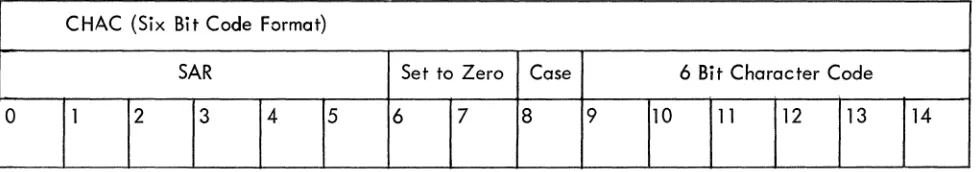
In the 6-bit format, an identical process takes place except that the leftmost six bits are first gated onto the CHAC and the right six bits are put in a character save (CS) register. The CS register is gated onto the low order six bits of the CHAC when the first character is complete. The CB register is a Iso set to a one, indicating execution of the left character.
Along with the six character bits, the CASE bit is gated into bit 8, allowing reference to 128 characters by a 6-bit character code.
CHAC (Six Bit Code Format)
SAR Set to Zero Case 6 Bit Character Code
[image:44.612.61.550.593.679.2]PROGRAMMED BUFFERED DISPLAY 338
The dispatch word obtained from the location specified by the CHAC is interpreted in the same way whether the six or seven bit format was used.
In the dispatch word, bit position 0 indicates whether the dispatch table word is a control word (bit 0=1) or a dispatch word (bit 0=0). If it is a dispatch word, the character can be drawn in either increment or short vector mode. Bit 1 in the dispatch word indicates the mode. If the bit is 0, the data is accepted
in increment mode; if it is 1, the data is accepted in short vector mode. The low order ten bits are used as the dispatch address and are gated onto the low order ten bits of the CHAC.
Dispatch Word
Mode Address
0 1 2 3 4
5
6 7 8 9 10 110
CHAC During Dispatch
SAR Over- Dispatch Address
Lap
0 1 2 3 4 5 6 7 8 9 10 11 12 13 14
Both the SAR and the dispatch address reference bit 5 in the CHAC. The bit is the inclusive OR of these two registers. In other words, if the SAR is odd (i .e., bit 5 is a 1), the dispatch address can only reference 512 10 locations, whereas, if the SAR is even, the table can reference 102410 locations.
A 1. J CONTROL CHARACTERS
If the dispatch table word has bit 0=1, a dispatch does not take place, but rather the word is accepted in one of three special formats indicated by bits 1 and 2. After execution of the control char-acter, the next character is immediate Iy fetched.
A1.1.1 Parameter Control