Systems Reference Library
Tape Input/Output Instructions
IBM 1401 Data Processing System
IBM 1460 Data Processing System
This publication contains a description of the instructions and timings used by the IBM 1401 and
1460 Data Processing Systems to operate the tape units attached to them. The instructions and timings for the following tape units are included in this publication:
IBM 729 Magnetic Tape Unit
IBM 7330 Magnetic Tape Unit IBM 1011 Paper Tape Reader IBM 1012 Tape Punch
Preface
This publication is a portion of the reference text for the IBM 1401 and 1460 Data Processing Systems. The full set of manuals provides a detailed explanation of all the instructions used by the system to manipulate data. Detailed explanations of the instructions used with the required and available input/output units at-tached to the system are also included. The reader should be familiar with the IBM 1401 System
Sum-mary, Form A24-1401, or the IBM 1460 System Sum·· mary, Form A24-1496, and the various publications on
programming material, such as Symbolic Programming System (SPS) and Autocoder.
The complete manual is divided functionally into these sections:
System Operation Reference Manual (A24-3067)
Section A Section B Section C Section D Section E
Introduction System Operations IBM 1406 Operations IBM 1447 Operations
IBM 1402 and 1403 Operations
Minor Revision, November 1964
This publication, A24-3069-2, is a minor revision of A24-3069-1. It does not, however, obsolete the previous publication. The only change in this revision is the removal of all the IBM 1440 Data Processing System references and timings.
Tape Input/Output Instructions (A24-3069) Section F Tape Input/Output Operations
Disk Input/Output Instructions (A24-3070) Section G Disk Input/Output Operations
Miscellaneous Input/Output Instructions (A24-3068) Section H Miscellaneous Input/Output
Oper-ations
Special Feature Instructions (A24-3071) Section I Special Feature Operations
The sections arc independent and do not have to be used in the order in which they appear. A System Reference Library can be compiled using those sec-tions applicable to the user's machine configuration.
This publication is intended for programmers and systems personnel who have a general knowledge of the IBM 1401 or 1460 Data Processing Systems and who require a reference text for detailed information.
Other publications referenced here are, in most cases, prerequisites for a complete understanding of the material presented in this publication.
Copies of this and other IBM publications can be obtained through IBM Branch Offices.
Address comments concerning the content of this publication to IBM Product Publications, Endicott, New York 13764.
Contents
Tape Input/Output Instructions "... F-l Magnetic Tape Operations ... F-l Magnetic Tape Instructions ... ... F-2 Magnetic Tape Operating Considerations ... F-7 Magnetic Tape Timing ... F-7
IBM 1011 Paper Tape Reader ... F-14
Instructions F-14
IBM 1012 Tape Punch ... F-16 Instructions ... ,,,... F -16 IBM lO12 Programming Concepts ... F-20 IBM lO12 Read Feature (Special Feature) ... F -26
Magnetic-Tape Operations
Tape Units
IBM 729 Magnetic Tape Unit (Figure F-l)
The 1401 system can use either of four models of the IBM 729 Magnetic Tape Units (Model II, Model IV, Model V, and Model VI). (The Model VI operates at Model IV speeds only.) The 1460 system can use 729 II, 729 IV, 729 V, or 729 VI magnetic-tape units. Either. tape-oriented system can accommodate as many as six IBM 729 tape units which are attached to the tape adapter on the 1401 (attached to the 1461 on the 1460). The IBM 729 dual-density tape unit makes it possible for the IBM 729 tape unit to operate with magnetic tapes recorded at either 200, 556, or 800 characters per inch.
Figure F-l. IBM 729 Magnetic Tape Unit
Tape Input-Output Instructions
Figure F-2. IBM 7330 Magnetic Tape Unit
IBM 7330 Magnetic Tape Unit (Figure F-2)
The 1401 and 1460 systems can also use the 7330 tape units as an input-output medium. The primary differ-ence between the 7330 and the 729 tape units is the procesing speed.
Data Flow
IBM magnetic-tape units function in the systems as both input and output devices. They transport the magnetic tape and accomplish the actual reading and writing of information, as directed by outside control from the stored program.
[image:5.612.326.541.155.492.2] [image:5.612.68.309.361.704.2]Magnetic
Tape Instructions
Read Tape
Instruction Format.
Mnemonic
SPS MU
A RT
Op Code
M
A-address B-address d-character
%Ux xxx R
Function. The tape unit specified in the A-address is started. The d-character specifies a tape read opera-tion. The B-address specifies the high-order position of the tape read-in area of storage. The machine begins to read magnetic tape, and continues to read until either an inter-record gap in the tape record or a group-mark with a word-mark in core storage is sensed. The inter-record gap indicates the end of the tape record, and a group mark (code CBA 8421) is inserted in core storage at this point.
If the group-mark with a word-mark occurs before the inter-record gap is sensed, the transfer of data from tape stops, but tape movement continues until the inter-record gap is sensed.
Word Marks. Word marks are not affected.
Timing. T = N (LI
+
1) ms+
T:\I. Time varies for type of tape unit and tape density used (see Timing section). N = .0115 (1401), .006 (1460)Address Registers After Operation.
I-Add. Reg.
NSI
A-Add. Reg.
%4x
B-Add. Reg.
Group mark + 1
Example. Read the record from tape unit 2 (labeled 2) into core storage. The high-order tape-record char-acter is moved to INPUT (0419), the next charchar-acter is moved to the next higher position (0420), etc., until transfer of data is stopped by an inter-record gap in the tape record, or a group-mark with a word-mark in core storage (Figure F -3).
Autocoder
OPERAND
!K!
Assembled Instruction: fA %U2 419 R Figure F -3. Read Tape (Move Operation)
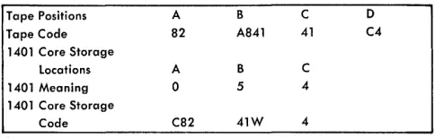
Tape Positions A B C 0
Tape Code 82 A841 41 C4
1401 Core Storage
Locations A B C
1401 Meaning 0 5 4
1401 Core Storage
Code C82 41W 4
Figure F-4. Word-Separator Character Handling During Read Tape with Word Marks Operation
Read Tape with Word Marks
Instruction Format.
Mnemonic
SPS LU
A RTW
Op Code
L
A-address
%Ux
B-address d-character
xxx R
Function. With the following two exceptions, this in-struction is the same as READ TAPE. Word-separator characters (written with WRITE TAPE WITH WORD MARKS instruction) are translated to word marks during transmission into core storage. As in all load instructions, word marks encountered in the B-field will be cleared.
Word Marks. A word-separator character read from tape causes a word mark to be associated with the next tape character transferred into core storage
(Figure F -4) .
Timing. T
=
N (LI+
1) ms+
Tl\I.Note. If a record has been written on tape by a WRITE TAPE WITH WORD MARKS instruction, it should be read back by a READ TAPE WITH WORD MARKS instruction so that word
separa-tor characters will be translated to word marks.
Address Registers After Operation.
I-Add. Reg. A-Add. Reg. B-Add. Reg.
NSI %4x Group-mark
+
1Example. Read the record from tape unit 5 (labeled 5) into core storage, and insert word marks where word-separator characters exist in the tape record. The high-order character is moved to INRECI (0518), the next character is moved to the next higher position (0519), etc., until the transfer of data is stopped by an inter-record gap in the tape record, or until a group-mark with a word-mark is sensed in core storage (Figure F -5) .
Autocoder
I'
labelOPERAND
.
:Assembled Instruction:! %U5 518 R Figure F-5. Read Tape with Word Marks (Load Operation)
[image:6.613.310.552.65.142.2]Instruction Format.
Mnemonic SPS MU A WT
Op Code
M
A-address %Ux
B-llddress d-character
xxx W
Function" The tape unit designated in the A-address is
started. The d-character specifies a tape write opera-tion. The data from core storage is written on the tape record. The B-address specifies the high-order position of the record in storage. A group-mark with a word-mark in core storage stops the operation. The group-mark with a word-mark causes an inter-record gap on the tape.
,V ol'd ~.[ arks. \V ord marks are not affected.
Timing. T = N (LI -+-1) ms + T!\!.
Note. If a group-mark with a word-mark is the first character of B-address, the tape-adapter unit and the tape unit will hang up. The condition can be reset by pressing the start-reset key if the tape-select switch on the system console is in the N ( normal) position.
Address Hegisters After Operation.
I-Add. Reg. NSI
A-Add. Reg. %4x
B-Add. Reg.
Group mark
+
1Example. Transfer the contents of core storage to tape
unit 3 (labeled 3), starting at the location labeled OUTPUT (0525) and endilng at the location of the first group-mark with a word-mark (Figure F -6).
Assembled Instruction: M %U3 525 W
FigureF-6. Write Tape ( Move Operation)
Write Tal)e with Word Marks
1 nstruction Format.
Mnemonic SPS LV
A WTW
Op Code
L
A-address %Ux
B-address d-character
xxx W
Function" This is the same as the write tape operation
except that the WRITE TAPE WITH WORD MARKS in-struction affects word marks in core storage.
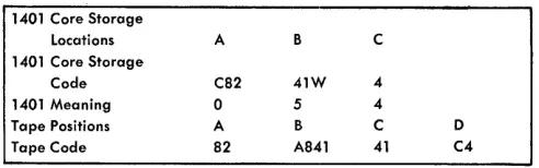
1401 Core Storage
locations A B C
1401 Core Storage
Code C82 41W 4
1401 Meaning 0 5 4
Tape Positions A B C 0
Tape Code 82 A841 41 C4
Figure F -7 . Word -Separator Character Handling During Write Tape with Word Marks Operation
Word Marks. A word mark associated with any
posi-tion in core storage causes a word-separator charac-ter (A841) to be written automatically on tape, one character ahead of that which contained the word mark. Thus, word marks are translated to word-separator characters for tape storage (Figure F -7).
Timing. T = N (LI -+-1) ms
-+-
T:\!.Note. Load operations must be used when word marks are
needed for identification in tape storage. If tape is written by a WRITE TAPE WITH WORD MARKS instruction, it must be rcad
back by a READ TAPE WITH WORD MARKS instruction to ensure proper translation between the tape and core storage.
Address Registers After Operation.
I-Add. Reg. A-Add. Reg. B-Add. Reg. NSI %4x: Group mark + 1
Example. Transfer the contents of core storage to tape
unit 6 (labeled 6). Insert a word-separator character where word marks exist in core storage, beginning at OUTREC (0696) and ending at the first group-mark with a word-mark in core storage (Figure F -8).
Autocoder
Assembled Instruction:.I:: %U6 696 W Figure F -8. Write Tape with Word Marks
Backspace Tape Record
Instruction Format.
Mnemonic SPS CU A BSP
017 Code
U
.A-address %Ux
d-character
B
Function. The tape unit specified in the A-address
[image:7.612.329.575.54.131.2]inter-record gap (IRG) encountered stops the backspace operation specified by the d-character, B.
Word Marks. \Vord marks are not affected.
Timing. T
=
N (LI+
1) ms+
TH.Note. The system is interlocked for the duration of tapc
move-ment, for any instructions that have a percent (%) sign in the hundred's position of the A-address. Other functions are not affected.
Address Registers After Operation.
I-Add. Reg.
NSI
A-Add. Reg. %4x
B-Add. Reg.
dbb
Example. Backspace tape unit 4 (labeled 4) until an IRG is sensed (Figure F -9) .
Autocoder
~
Label.
:
Assembled Instruction: Y %U4 B Figure 1"-9. Backspace Tape Record
Skip and Blank Tape
Instruction Format.
Mnemonic SPS CU A SKP
Op Code
Q
A-address %Ux
OPERAND
:~
.
:
d-character
E
Function. The tape unit, designated by the A-address, spaces forward and erases approximately 3.5 inches of tape. The actual skip occurs when the next WRITE TAPE instruction is given. This instruction makes it possible to bypass defective tape areas.
Word Marks. Word marks are not affected.
Timing. T= N (Lr
+
1) ms. Processing can continue immediately after this operation. However, 40.5 ms for IBM 729 II, 27 ms for IBM 729 IV, 40.5 ms for IBM 729 v, 27 ms for IBM 729 VI (1460 only), and 108 ms for an IBM 7330 must be added to the next WRITE TAPE instruction time.Notes. The SKIP AND BLANK TAPE instruction should be given immediately preceding a WRITE TAPE instruction for the tape
unit specified by both instructions.
The system is interlocked for the duration of tape move-mcnt, for any instructions that have a percent sign (%) in the hundred's 110sition of the A-address. Other functions are not affected.
Address Registers After Operation.
I-Add. Reg.
NSI
A-Add. Reg. %4x
B-Add. Reg.
dbb
Example. Erase tape on tape unit 5 (labeled 5) when the next write operation is ordered for that unit (Figure F -10).
Autocoder
Assembled Instruction:!l %U5 E Figure F-lO. Skip and Blank Tape
Write Tape Mark
Instruction Format.
Mnemonic SPS CU A WTM
Op Code
!L
A-address %Ux
d-character
M
Function. This instruction causes a tape mark charac-ter (8421) to be recorded immediately following the last record on tape. When the tape mark is read back from a .tape, the end-of-reel indicator is turned on. This signals the system program that the end of a major group of records has been reached (end-of-file) or the end of utilized tape has been reached.
"Vard Marks. Word marks are not affected.
Timing. T
=
N (LI+
1) ms+
TM •Note 1. The system is interlocked for the duration of tape
movement, for any instructions that have a percent sign (%) in the hundred's position of the A-address. Othcr functions are not affected.
Note 2. A group mark will be read into the second position of
the tape read-in area unless this position contained a group-mark with a word-group-mark. In this case, the group-group-mark with a word-mark will be regenerated into this position.
Address Registers After Operation.
I-Add. Reg.
NSI
A-Add. Reg. %4x
B-Add. Reg.
Example. Insert a tape mark on the tape in tape unit 3 (labeled 3), Figure F-11.
OPERAND
40 411 ao
Assembled Instruction: M O/OU3 M Figure F-ll. Write Tape Mark
Diagnostic Read
Instruction Format.
Mnemonic SPS (none)
A (none)
017 Code
U
A-address
%Bx or %Ux
d-character A
Function. This instruction causes the tape unit speci-fied in the A-address to reposition its tape to the next inter-record gap (IRG) without transmitting any data to core storage. If the tape record contains a first character tape mark, the end-of-file (EOF) indicator is turned on.
This instruction is usefUlI in skipping records or files on tape. The system is free to proceed with in-ternal processing during the tape movement.
The tape operations are interlocked until the check character of the record being skipped is sensed.
Word Marks. Word marks are not affected.
Timing. T
=
N (L[+
1) ms -I-Tl\I.Note. The system is interlocked for the duration of tape
move-ment, for any instructions that have a percent sign (%) in the hundred"s position of the A-address. Other functions are not affected.
Rewind Tape
Instruction Format.
Mnemonic SPS CU
A RWD
OJ) Code
!l
A-address
%Ux
d-character
R
Function. This instruction is usually given after an end-of-reel condition, and causes the selected tape unit to
rewind the tape. When the operation is initiated, the tape unit is, in effect, disconnected from the system.
Word "fvlarks. Word marks are not affected.
Timing. T
=
N (Lr + 1) ms. Rewind time is 1.2 minutes per 2,400-foot reel for the IBM 729 II, .9 minute for the IBM 729 IV, 1.2 minutes for the IBM 729 v, .9 minute for the IBM 729 VI (1460 only), and 13.3 min-utes for the IBM 7330, but it is not calculated with program time. Processing can continue approxi-mately 10 ms after this instruction is interpreted.Note. Processing unit not interlocked during tape-movement
time.
Address Registers After Operation.
I-Add. Reg. A-Add. Reg. B-Add. Reg.
NSI %4x dbb
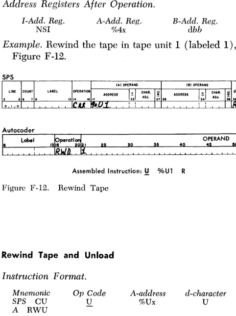
Example. Rewind the tape in tape unit 1 (labeled 1), Figure F -12.
Autocoder
Assembled Instruction: M %Ul R Figure F-12. Rewind Tape
Rewind Tape and Unload
Instruction Format.
Mnemonic SPS CU A RWU
Op Code
U
A-address
%Ux
d-character
U
Function. This instruction causes the tape unit speci-fied in the A-address to rewind its tape. At the end of the rewind, the tape is out of the vacuum columns, and the reading mechanism is disengaged. The unit is effectively disconnected from the system, and is not available again until the operator restores it to a ready status.
Word Marks. Word marks are not affected.
[image:9.613.329.570.241.564.2]the IBM 729 IV, 1.2 minutes for the 729 v, .9 minute for the 729 VI (1460 only), and 2.2 minutes for the IBM 7330, but it is not calculated with program time. Processing can continue approximately 10 ms after this instruction is interpreted by a system using IBM 729 tape units, or 4.5 seconds in a system using IBM 7330 tape units.
Note. Processing unit not interlocked during tape-movement time.
Address Registers After Operation.
I-Add. Reg.
NSI
A-Adcl. Reg.
%4x
B-A(ld. Reg.
dbb
Example. Rewind the tape in tape unit 5 (labeled 5), and make it unavailable to the stored program, at the completion of the rewind operation (Figure F-13).
Autocoder Label
. :
Assembled Instruction: Y %U5 U Figure F-13. Rewind Tape and Unload
Branch if End of Reel
Instruction Format.
Mnemonic
SPS B A BEF
Op Code B
I-address
xxx
d-character K
Function. The end-of-reel (EOR) indicator turns on in the system processing unit if a tape mark is read by the system or if a reflective spot is sensed during a write tape operation. This instruction tests the indi-cator and causes an automatic branch to the 1-address if the indicator is ON. If it is OFF, the pro-gram continues normally.
Word Marks. Word marks are not affected.
Timing.
Without indexing: T
=
N (LI+
1) ms. "Vith indexing:T
=
N(LI+
2)ms.'Note. This instmction must be executed immediately following a tape read or tape write operation to ensure correct results and reset the EOR indicator OFF, if it is ON. If another tape unit is selected before a BRANCH IF END-OF-REEL INDICATOR ON instruction is executed, the indicator remains ON and a false EOR condition specifying the wrong tape unit results.
Address Registers After Operation.
I-Add. Reg. A-Add. Reg.
NSI BI
B-Add. Reg.
dbb
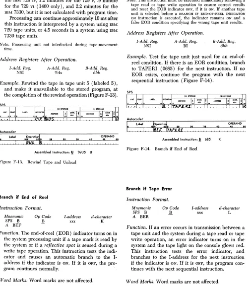
Example. Test the tape unit just used for an end-of-reel condition. If there is an EOR condition, branch to TAPER1 (0685) for the next instruction. If no EOR exists, continue the program with the next sequential instruction (Figure F -14).
Autocoder
Assembled Instruction:! 685 Figure F -14. Branch if End of Reel
Branch if Tape Error
Instruction Format.
Mnemonic
SPS B
A BER
Or Code B
I-address
xxx
K
d-character L
Function. If an error occurs in transmission between a tape unit and the system during a tape read or tape write operation, an error indicator turns on in the system and the tape light on the console glows red. This instruction tests the error indicator, and branches to the I -address for the next instruction if the indicator is ON. If it is OFF, the program con-tinues with the next sequential instruction.
Word Marks. Word marks are not affected.
Timing.
Without indexing: T
=
N (LI+
1) ms. With indexing: [image:10.612.57.561.62.642.2]Note. The BRANCH IF TAPE ERROR instruction must be given after a tape read or write operation, because any tape opera-tion on any tape unit causes the indicator to turn off. The information read from tape always enters core storage with odd-bit parity.
Address Registers After Operation.
I-Add. Reg.
NSI
A-Add. Reg.
BI
B-Add. Reg.
dbb
Example. Read a tape record from the tape unit 3 (labeled 3) into core-storage area labeled TAPEIN (0629) and test for a tape error. If there is an error, branch to T APER2 (0539) for the next instruction.
If there is no error, continue processing with the next sequential instruction (Figure F -15).
SPS
(AI OPERAND (BIOPERAND LINE COUNT LABEL OPERATIOfi ADDRESS I:!: I CHAR. g ADDRESS I ± I CHAR. ~ d
1314 18 11 2~1 ADJ. 27 28 _~341 ADJ.
fL---"If'--'+"---"'IIM;.:;..,-!U-,-r"'l.:~~.u.=-~--...,:c=--: -, -,--+'-'+=Ii~·,A--,P -:E, I .N! : IR
.-L-'--fl.IR~__+' -I-fTuA'..!."P!-,,,,,-E,,,-,,,,,,t:t,/t,-,-: --L: -'--.L--+-I-'-L-'--'-~-+--'-'-f--+~
Autocoder
S.
L~I:---r----r---O-PE-RA-N-O--30 3!! 40 45 50
IN
Assembled Instru(:tion:.M %U3 629 R
! 539
Figure F -15. Branch if Tape Error
Magnetic-Tape Operating Considerations
IBM 729 Magnetic Tape UnH
If the 729 is in write status, to change to read status the program must backspace over those records that are to be read. The tape unit must then be changed back to write status (W 1> W 2, W 3, Ba, B2 , R2 , R3 , W 4, W ... ). This resuIts in unchecked tape on the first record written after backspace.
The 729 cannot be switched directly from write to read status (WI, W 2, R3 , R4)"
If the 729 is in read status, the tape unit can be changed directly from read to write status (Rl, R2,
W3 , W4 ).
IBM 7330 Magnetic Tape Unit
If the 73.30 is in write status, to change to read status the program must backspace over those records that are to be read. The tape unit must then be changed back to write status ( WI, W:2, W 3, Bs, B2 , R2 , Rs, W 4,
W .... ). This results in unchecked tape on the first record written after backspace.
The 7330 cannot be switched directly from write to read status (W 1, W 2, R3 , R4)'
If the 7330 is in read status, to change to write status the program must backspace over the last record read and then rewrite that record. The 7330 then continues in write status (R1 , R!,!, B2 ,
vV
2 , W3 , W .... ).The 7330 cannot be switched directly from read to write status (R1' R2 , W3 , W4 ).
Figure F-16 is a summary of 1401 and 1460 mag-netic-tape operating considerations.
F or detailed inform a tion concerning. magnetic tape and IBM magnetic-tape units, refer to the IBM Refer-ence Manual, Magnetic Tape Units, Form A22-6589.
Dust or damage to the magnetic tape is the most fre-quent cause of errors detected during write operations. Such imperfections are usually isolated; so, in order to skip the defective section, the system has been pro-vided with an instruction that causes the tape to space forward approximately 3.5 inches when the next write operation is initiated. While the tape is passed, this short length is erased so that extraneous data is not sensed when the tape is read. The tape-write operation continues after the skip is completed.
When writing from load point, a space of 3.5 inches also occurs prior to writing the record, and start time is increased about 27 milliseconds.
Magnetic Tape Timing
All tape units in a 1401 system are under the control of a tape-adapter unit (a 1461 on the 1460 system). The tape-adapter unit (TAU) can control the operations of only one tape unit at a time. If one tape unit is busy, no other tape unit can be used until all operations on the busy one have been completed. The execute time of a tape instruction varies according to the type and model tape units used in the system.
C is the character rate in milliseconds- based on the setting of the tape density switch.
N is the number of characters in the record. CN is record time (number of characters in the rec-ord, times the character rate).
Start time is the time necessary for the tape unit to accelerate to operating speed.
Stop time is the time necessary for the tape unit to decelerate and stop.
Record check time is the time it takes to read or write the check character. This time is based on the read-write head gap (the distance that separates the read and write heads) and the time it takes a single character written on tape to travel from the write head to the read head.
CAN BE PERFORMED
STATUS OPERATION 729 REMARKS 7330 REMARKS
RL BL Wl W 2 W---- Yes Updating tape label Yes Updating tape label
Rl R2 Skip Ws W---- Yes Results in unchecked tape Yes Results in unchecked tape
Skip must be over known blank area Read Rl R2 Ws W---- Yes Unchecked tape in record Wa No Write head is over first part of next
record (Ws)
Rl Bl Wl R2 No Changing from W to R causes bits No Changing from W to R causes bits in the inter-record gap in the inter-record gap
WL B1 Rt W2 W---- Yes Unchecked tape on record W2 Yes Unchecked tape on record W2 Wi W2 Blank Area Ra R---- Not Results in bits in the inter-record gap Not Results in bits in the inter-record gap
Recom. and possible error on Rs Recom. and possible error on Rs
Write WI W 2 Ra R4 No Changing from W to R causes bits No Changing from W to R causes bits in the inter-record gap in the inter-record gap
WI B1 Rl R2 No Changing from W to R causes bits No Changing from W to R causes bits in the inter-record gap in the inter-record gap
Rs R4 R5 Rw Yes Yes
Rewind Ws W.I We Rw Yes Causes extraneous bits after Yes Causes extraneous bits after
R -read W -write B -backspace Rw-rewind
W5 {label) Wr; {label)
Figure F-16. Summary of IBM 1401 and 1460 Magnetic Tape Operating Considerations
or writing a record and the start time is increased a bou t 27 milliseconds.
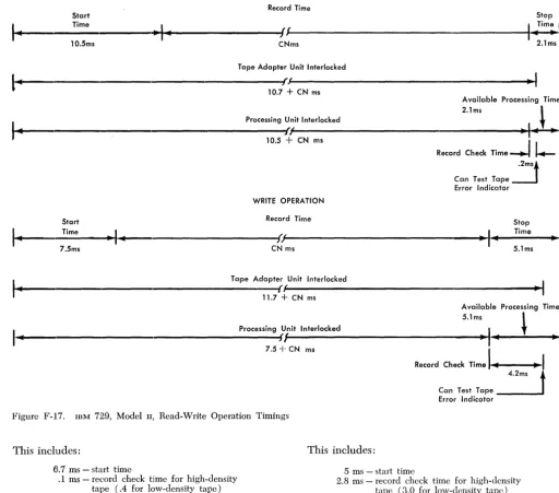
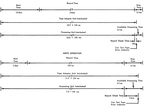
IBM 729 II Tape Timings
During a 729 II read operation, the tape adapter unit or 1461 is interlocked for 10.7
+
eN
ms (Figure F-17). This includes:10.5 ms - start time
.2 ms - record check time for high-density tape (.6 for low-density tape) CN ms - record time
During the same read operation, the processing unit is interlocked for 10.5
+
eN
ms. This includes:10.5 ms - start time CN ms - record time
Therefore, in a tape-read operation, processing can take place during the 2.1-ms stop time. A tape-trans-mission-error condition can be recognized .2 ms after the processing interlock is released. If the tape trans-mission-error-test instruction is given during this .2 ms period, the processing unit is interlocked until the error indicator can be tested.
During a 729 II tape write operation, the tape-adapter unit or 1461 is interlocked for 11.7
+
eN
ms (Figure F -17). This includes:7.5 ms - start time
4.2 ms - record check time for high-density tape (4.6 for low-density tape) CN ms - record time
During the same write operation, the processing unit is interlocked for 7.5
+
eN
ms. This includes:7.5 ms - start time CN ms - record time
Therefore, in a tape-write operation, processing can take place during the 5.1 ms stop time. A tape-trans-mission-error condition can be recognized 4.2 ms after the processing interlock is released. If the tape-trans-mission-error-testinstruction is given during this 4.2 ms period, the processing unit is interlocked until the error indicator can be tested. The difference between the .2 ms record check time of reading and the 4.2 ms record check time of writing is due to the read-write head gap time (4.0 ms).
For job-timing estimates of tape read-write opera-tion, the normal formula 10.8
+
eN
ms can be used.IBM 729 IV Tape Timings
During a 729 IV read operation, the tape-adapter unit or 1461 is interlocked for 6.8
+
eN
ms (Figure F-18). [image:12.617.50.546.56.342.2]READ OPERATION Rec:ord Time
Start Stop
Time ~ _ _ _ _ _ _ _ _ ----tI_Tim~,
~---·---""""'~~""---""---11f-
.
I-
..,1 ..
10.5ms CNms 2.1ms
Tape Adapter Unit Interlocked
~---ifw~<---~·~I
l~
10.7 + CN ms
Available Processing Time
I
~
2.1ms ,
Processing Unit Interlocked
t
I
~---·---·---~fl~(---.~I~-~~'
10.5+
CN msI
Record Check Time
~
~
.2ms. Can Test Tape---.l Error Indicator WRITE OPERATIONStart Record Time Stop
I-
Time·1-
I
TimeI
~""---~~~----'---i{J~(---~'~~~-~----
.... --••
~7.5ms CN ms 5.1ms
I·
~""----'---·---....
Tape Adapter Unit Interlocked ---~{~/---11.7 + CN ms.... --....
---""----~~"I
Available Processing Time
5.1 ms ,
I •
. . ______ • __________________ , ____ .... __________ p_r_o_ce_s_Si_n_g~~~,-it-l-n-te_r_lo_c_ke_d 7.5+
CN ms __________________________ ~,~I~~..
~---t--....
-.1II'11Figure F-17. IBM 729, Model II, Read-Write Operation Timings
This includes:
6.7 ms - start time
.1 ms - record check time for high-density tape (.4 for low-density tape)
eN ms - record time
During the same read operation, the processing unit is interlocked for 6.7
+
CN ms. This includes:6.7 ms - start time
eN ms - record time
Therefore, in a tape-read operation, processing can take place during the 2.I-ms stop time. A tape-trans-mission-erroT condition can be recognized .1 ms after the processing interlock is released. If the tape-trans-mission-error-test instruction :is given during this .I-ms period, the processing unit is interlocked until the error
indicator can be tested. .
During a 729 IV tape write operation, the tape-adapter unit or 1461 is interlocked for 7.8
+
CN ms(Figure F-I8).
This includes:
5 ms - start time
Record Check Time 1 ... 1If .. - - - - -..
,~1
4.2mst
Can Test Tape _____ _Error Indicator
2.8 ms - record check time for high-density tape (3.0 for low-density tape)
eN ms - record timc
During the same write operation, the processing unit is interlocked for 5
+ eN
ms. This includes:5 ms - start time
eN ms - record time
[image:13.618.63.576.68.519.2]READ OPERATION
Start Record Time Stop
Time
I-
-I -
I
TimeI
~---~I~---~---~!f~---~·~
6.7ms.•• --••
~.
CN ms 2.1ms
I-
Tape Adapter Unit Interlocked~---~h~/---·-~I
6.8+
CN msAvailable Processing Time
I-2.1ms \
~ _________________________________________ pr_o_ce_s_si_n_g~l:~/t __ ln_t_er_lo_c_ke_d _______________________________ ~~I~
6.7
+
CN msRecord Check
Time~1 ~
.1JS
Can Test Tape Error Indicator WRITE OPERATION
Record Time
Start Stop
I
TimeI
~---.~~---iJf~---.-~·~-~--~-~.
I
-Time
~
I-5 ms CN ms 3.8ms
Tape Adapter Unit Interlocked
I-~---~SSr---~·~1
7.8
+
CN msAvailable Processing Time
Processing Unit Interlocked 3.8ms \
f{
I-
5+
CN ms-I-
-I
Record Check Time
H
2.sm'1
Can Test TapeFigure F-18. II3M 729, Model IV, Read-Write Operation Timings
For job-timing estimates of tape read-write opera-tions, the nominal formula 7.3
+
eN
can be used.IBM 729 V Tape Timings
During a 729 v read operation, the tape-adapter unit or 1461 is interlocked for 10.7
+
eN
ms (Figure F-19).This includes:
10.5 ms - start time
.2 ms - record check time for high-density tape (.6 for low-density tape)
eN ms - record time
During the same read operation, the processing unit is interlocked for 10.5
+
eN
ms. This includes:10.5 ms - start time
eN ms - record time
Therefore in a tape-read operation, processing can take place during the 2.1-ms stop time. A tape-trans-mission-error condition can be recognized .2 ms after the processing interlock is released. If the
tape-trans-Error Indicator
mission-error-test instruction is given during this .2-ms period, the processing unit is interlocked until the error indicator can be tested.
During a 729 v write operation, the tape-adapter unit or 1461 is interlocked for 11.7
+
eN
ms (Figure F -19). This includes:7.5 ms - start time
4.2 ms - record check time for high-density tape (4.6 for low-density tape)
During the same write operation, the processing unit is interlocked for 7.5
+
eN
ms. This includes:7.5 ms - start time
eN ms - record time
Therefore in a tape-write operation, processing can take place during the 5.1-ms stop time. A tape-trans-mission-error condition can be recognized 4.2 ms after the processing interlock is released. If the tape trans-mission-error-test instruction is given during this 4.2-ms
[image:14.615.49.555.61.424.2]READ OPERATION Record Time
Start Stop
Time
I ..
Tim=. ,~---.---~~'---~J,~(---~.~-~~~~.
I ..
..I ..
10.5ms CNms 2.1ms
Tape Adapter Unit Interlocked
~---~f.~(---~
..
I
llll
10.7
+ CN ms
Available Processing Time
I
III2.1 ms ,
Processing Unit Interlocked ,
~---.---~{)~(---~·~I~III.-~·~1
10.5+
CN mst
Record Check Time
-..I
t...
.2ms. Can Test Tape----.J Error Indicator WRITE OPERATIONStart Record Time Stop
I ..
Time... 1111
I
TimeI
~---~~---~f(~{---~·~
••
---~.~7.5ms CN ms 5.1ms
I·
~---.---~{.~(---·
Tape Adapter Unit Interlocked 11.7 + CN ms...
~I
Available Processing Time
5.1ms ,
I
IIIProcessing Unit Interlocked
I
t
..
I
~----'---·---~ff~---~·~4~111---~~.
7.5
-+
CN msI
Figure F-19. Il3M 729, Model v, Read-Write Operation Timings
period, the processing unit is interlocked until the error indicator can be tested. The difference between the .2-ms record check time of reading and the 4.2-ms rec-ord check time of writing is due to the read-write head gap time (4.0 ms).
For job-timing estimates of tape read-write opera-tions, the nominal formula 10.8
+
eN
ms can be used.IBM 729 VI Tape Timings
During at 729 VI read operati.on, the tape-adapter unit or 1461 is interlocked for 6.8
+
eN
ms (Figure F-20). This includes:0.7 ms - start time
.1 ms - record check time for high-density tape (.4 for low-density tape) CN ms - record time
During the same read operation, the processing unit is interlocked for 6.7
+
eN
ms. This includes:6.7 ms - start time
eN ms - record time
Record Check Time ... - - - 1 .... 1
4.2ms
t
Can Test Tape _ _ _ ---'Error Indicator
Therefore in a tape-read operation, processing can take place during the 2.I-ms stop time. A tape-trans-mission-error condition can be recognized .1 ms after the processing interlock is released. If the BRANCH IF TAPE ERROR instruction is given during this .I-ms period, the processing unit is interlocked until the error indicator can be tested.
During a 729 VI write operation, the tape-adapter unit or 1461 is interlocked for 7.8
+
eN
ms (Figure F -20). This includes:5 ms - start time
2.8 ms - record check time for high-density tape (3.0 for low-density tape)
During the same write operation, the processing unit is interlocked for 5
+
eN
ms. This includes:5 ms - start time CN ms - record time
[image:15.613.74.579.66.437.2]tape-trans-READ OPERATION
Start Record Time Stop
Time
I
~
-I
~
I
TimeI
~---~I~---~!J~---~.~-~4--.'~-
6.7ms CN ms 2.1ms14
Tape Adapter Unit Interlocked
/.'
I6.8
+
CNms
Available Processing Time
I •
2.1ms \
Processing Unit Interlocked ~
~---~f/~/---~.41~_~~_~1
6.7+
CN msRecord Check Time
~Il..--.lJ5
Can Test Tape Error Indicator WRITE OPERATION
Record Time
Start Stop
I
4Time
'1-
.1
A Time.1
~---'~~---4f/~(---·~~-~~~--~~~-
5 msCN ms 3.8ms
Tape Adapter Unit Interlocked
I-
~---~5S~---~'~1
7.8+
CN msAvailable Processing Time
I-
~---~n~---~'~I-~~'I
Processing Unit Interlocked 3.8ms \5
+
CN msRecord Check Time
H
Figure F-20. IBM 729, Model VI, Read-Write Operation Timings
mission-error condition can be recognized 2.8 ms after the processing interlock is released. If the tape-trans-mission-error-test instruction is given during this 2.8-ms period, the processing unit is interlocked until the error indicator can be tested. The difference between the :l-ms record check time of reading and the 2.8-ms record check time of writing is due to the read-write head gap time (2.7 ms).
For job-timing estimates of tape read-write opera-tions, the nominal formula 7.3
+ eN
ms can be used.IBM 7330 Tape Timings
During a 7330 tape-read operation, the tape-adapter unit or 1461 is interlocked for 20.5
+ eN
ms (Figure F -21). This includes:10.3 ms - start time 9.8 ms - stop time
.4 ms - record check time for high-density tape (1.0 ms for low-density tape) eN ms - record time
208m't
Can Test Tape Error IndicatorDuring the same read operation, the processing unit is interlocked for lOA
+ eN
ms. This includes:10.3 ms - start time
.1 ms - part of the .4 ms record check time eN ms - record time
Therefore, in a tape-read operation, processing can take place during 10.1 ms of stop time and record-check time. A tape-transmission-error condition can be recognized .3 ms after the processing interlock is released.
During a 7330 tape-write operation, the tape-adapter unit is interlocked for 20.3
+ eN
ms (Figure F-21). This includes:5.0 ms - start time 6.6 ms - stop time
8.7 ms - record check time for high-density tape (9.3 ms for low-density tape) eN ms - record time
During the same write operation, the processing unit is interlocked for 5
+ eN
ms. This includes: [image:16.613.47.549.61.428.2]READ OPERA nON Record Time
S~rt ~op
~1~.
_________
T_im __ e ___________ '~~I~.____________________
--4f/~/ ____ ---~.~I 1~._~---T-i-m-e---.~~110.3 ms CN ms Ams 9.8 ms
I
~-
•.
..
----'---.---~J:~---~
Tape Adapter Unit Interlocked20 .. 5
+
CN msAvailable Processing Time 10.1 ms
Processing Unit Interlocked
1/
'---.---~/~---.~
~l:=
______
Can Test Tape 10.4+
CN ms.3 ms Error Indicator
WRITE OPERA nON
StlClrt Record Time Stop
I~~ne
r---s
msI
I
Time
-,I,~(----~·~~·.-.---~~~~·~---~·~I
CN ms 8.7ms 6.6msTape Adapter Unit Interlocked
---1.~!~---~
20.3+
CN msAvailable Processing Time 15.3 ms
~
Processing Unit InterlockedI
---~I,.I---~~---.~
>,
5
+
CN ms 8.7msFigure F-21. IBM 7330 Read-Write Operation Timings
Therefore, in a tape-write operation, processing can take place during the 15.3-ms stop time. A tape-trans-mission-error condition can be recognized 8.7 ms after the processing interlock. is released. If the tape-trans-mission-test instnLCtion is given during this 8.7 -ms period, the processing unit is interlocked until the error indicator can be interrogated. The difference between the .4-ms record check time of reading and the 8.7-ms record check time of writing is due to the read-write head gap time (8.3 ms).
For job-timing estimates of read operations in either high- or low-density, uSe the formula 20.1
+
C (N+
7) ms, where the factor C (7) is the record check time.For job-timing estimates of write operations in either high- or low-density, use the formula 19.9
+
C (N+
7) ms, where the factor C (7) is the record check time, and 8.3 IllS of the 19.9 ms is the read-write head gaptime.
[image:17.613.74.577.55.450.2]IBM 1011 Paper Tape Reader
The IBM 1011 Paper Tape Reader (Figure F -22) fDr the IBM 1401, and 1460 Data PrDcessing Systems is an input device controlled by stored prO'grams in the same manner as other input-output equipment (card reader, card punch, and printer).
InformatiDn punched in paper tape can be read by the IBM 1011 directly into. any area of 1401, Dr 1460 CDre storage. Any character punched in 5-track tele-graphic, 8-track IBM, Dr many O'ther paper-tape cDdes can be encoded into. any valid 1401/1460 character through the flexibility Df control-panel wiring O'n the tape reader.
Instructions
The instructions described in this section are for the IBM 1401, and 1460 Data Processing Systems.
Read from Paper Tape
Instruction F orrnat.
Mnemonic Op Code A-address B-address d-character
MU M %Pl BBB R
Figure F-22. IBM 1011 Paper Tape Reader
Function. This instruction causes data to' be read from the paper-tape reader into core storage, beginning at the B-address.
The M Op code specifies that the operation will be performed in the move mode. When the M operation code is used, word marks are not transferred into core storage with the data read from the paper tape, and word marks in the core-storage paper-tape read-in areas' are undisturbed. The A-address, %Pl, is the code assigned to both the IBM 1011 Paper Tape Reader and the IBM 1012 Tape Punch.
The B-address specifies the core-stDrage position (high-O'rder) that receives the first character O'f infor-mation from the paper-tape reader. The succeeding characters are read into. the adjacent higher-num-bered core-storage positions.
The d-character R specifies a read operation. The read operation ends either by detection of a group-mark with a word-group-mark in core storage (signifies the end of the read-in area), or by reading an EOR (end-of-record character) character punched in the tape.
Any paper-tape character can be used as an end-of-record character. Wiring the assigned end-of.., record character decode-exit hub to the end-of-rec-ord IN hub terminates the paper-tape read operation and enters a group mark in core storage.
Note. If a group-mark with a word-mark in core stor-age is used to terminate the paper-tape-read opeTa-tion, the character read into. the A-register, when the group-mark with a word-mark is sensed, will be lost.
Word Marks. Word marks are not affected.
Timing. T = N (LI
+
1) ms+
record- transmission time. N=
.0115 (1401), .006 (1460).Address Registers After Operation.
I-Add. Reg. A-Add. Reg. B-Add. Reg.
NSI %71 B
+
message length+
1Example. Read record from paper-tape reader 1 into core stDrage. The high-order paper-tape character is mDved to' READIN (541), the next character is moved
to' the next higher pDsition (542), etc., until the transfer of data is stopped. The transfer is stopped either by the detection of a group-mark with a word-mark in core storage (signifies the end of the read-in area), Dr by reading an EOR (end-of-record) charac-ter punched in the tape (Figure F -23).
Autocoder
~
label OPERAND:11. I 00
.
:
Assembled Instruction: M %P1 541 R
[image:18.612.44.540.203.699.2] [image:18.612.49.300.301.701.2]Read from Paper Tape with Word Marks
Instruction Format.
Mnemonlc Op Code A-address B-address d-character
LU L %Pl BBB R
Function. This instruction is similar to the READ FROM PAPER TAPE instruction, except that word marks are removed from the paper-tape read-in area in core storage, and word-separator characters read from the paper-tape reader causes the insertion of a word mark in core storage with the next character read from the 1011. The ~ Op code specifies that the operation will be performed in the load mode, which results in the word mark control already discussed.
Word Marks. Word marks are removed from the
paper-tape read-in area in core storage, and word-separator characters read from the paper-tape reader cause a word mark to be associated with the next character read from the 1011.
Timing. T
=
N (LI+
1) ms+
record transmission time.Address Registers After Operation.
I-Add. Reg. A-Add. Reg. B-Add. Reg.
NSI %71 B
+
message length+
1Example. Read record from paper-tape reader 1 into
core storage, except that word marks are removed from the paper-tape read-in area in core storage, and a word separator character read from the paper-tape reader causes a word mark to be inserted in core storage with the next character read from the 1011. The high-order paper-tape character is moved to RDPTWM (418), the next character is moved to the next higher position (419), etc., until the read oper-ation ends either by detection of a group-mark with a word-mark in core storage, or by reading an EOR (end-of-record) character punched in the tape (Figure F-24).
Autocoder
I'
L~~ _~~
I I __ra~ti1~
I__
U-~_~L-
U 10 _ _~
:so _ _~~
40 _ _~O~~_~_N_D~
45 00Lli
J.Plrio
Pi,WM, RAssembled Instruction: L %P1 418 R
Figure F-24. Read from Paper Tape with Word Mark
Branch if: Input-Output Indicator On
Instruction Format.
Mnemonic
BIN
Op Code
B
I-address
III
d-character
1
Function. When a parity error is detected during a
read operation, the PE hub provides an error output
(8-track tape only). When the error condition occurs, the error character is suppressed and a special out-put is made available on the paper-tape-reader con-trol panel. This signal can be used to either substi-tute a unique error character, or delete that position. Refer to CONTROL and SPECIAL PURPOSE hubs in IBM 1011 Paper Tape Reader, Form A26-5754.
The detected parity error also turns on the input-output error latch in the system. A paper-tape-read operation should always be followed by a BRANCH IF INPUT-OUTPUT INDICATOR ON instruction. This instruc-tion checks the status of the input-output error latch. If the latch is ON, the system branches to the error subroutine. If the latch is OFF, the program goes to the next sequential instruction.
Word Mm'ks. Word marks are not affected.
Timing.
No Branch:
T = N (LI
+
l)ms.Branch (without indexing):
T
=
N (LI+
l)ms.Branch (with indexing) : T
=
N (LI+
2) ms.Address Registers After Operation.
I-Add. Reg. A-Add. Reg. B-Add. Reg.
No Branch
(no indexing) NSI BI dbb
Branch
(no indexing) NSI BI Blank
Branch (with
indexing) NSI BI NSI
Example. Branch, if input-output indicator is on, to PARERR (661) error subroutine (Figure F -25 ).
Autocoder
l
Label O~~ND.
:
Assembled Instruction: B 661 1
Figure F -25. Branch if Input-Output Indicator On
Branch if Paper Tape Reader Ready
Instruction Format.
Mnemonic
BIN
Op Code
B
I-address
III
d-character
2
Function. This instruction checks the status of the
[image:19.612.332.566.645.682.2]not ready, when tested, the program goes to the next sequential instruction. If the paper-tape reader is ready, when tested, the program branches to the subroutine that begins at the core-storage position specified by the instruction I-address.
Word Marks. Word marks are not affected. Timing.
No Branch:
T=N(LI +1)ms.
Branch (without indexing): T = N (LI
+
1) ms. Branch (with indexing):T = N (LI
+
2) ms.Address Registers After Operation.
I-Add. Reg. A-Add. Reg. B-Add. Reg.
No Branch
(no indexing) NSI BI dbb
Branch
(no indexing) NSI BI Blank
Branch (with
indexing) NSI BI NSI
Example. Branch to READY (767) for the location of the subroutine controlling the paper-tape reader (Figure F -26) .
Autocoder
~
label OPERAND:'.
.
~
Assembled Instruction. ! 767 2
Figure F -26. Branch if Paper Tape Reader Ready
IB~
1012 Tape Punch
The IBM 1012 Tape Punch (Figure F -27) attached
to the IBM 1401, or 1460 Data Processing Systems is an
output device controlled by stored programs in the same manner as other input-output equipment (card reader, card punch, and printer).
The IBM 1012 Tape Punch operates at the rate of
150 tape characters per second, using 5-, 6-, 7-, or 8-track paper tape, supplied from a reel. Data, stored in the core-storage area of 1401, or 1460 systems and ready to be punched, is converted to the appropriate tape code by using a translation program that includes the appropriate stored code table.
Instructions
The instructions described in this section are for the 1401, and 1460 operating with the IBM 1012 Tape
Punch.
Figure F-27. IBM 1012 Tape Punch
Write on Tape Punch
Instruction Format.
Mnemonic Op Code A-address B-address d-character
MU M %P1 BBB W
Function. This instruction causes one vertical tape col-umlll to be punched. The M Op code specifies an operation in the move mode. When the M operation code is used, word marks are not transferred from core storage to the tape punch. The A-address, %PI, is the code assigned to both the mM 1011 Paper Tape Reader and the mM 1012 Tape Punch.
The B-address specifies the first core-storage posi-tion (high-order) of the 3-posiposi-tion field. The 3-posi-tion field contains the total bit configura3-posi-tion that will be punched in one vertical column in the tape. The d-character W specifies a write operation.
[image:20.617.313.553.62.401.2]Word Marks. Word marks are not affected.
Timing. T
=
N (LI+
1) ms+
transmission time. N=
.0115 (1401), .006 (1460).Address Registers After Operation.
I-Add. Reg.
NSI
A-Add. Reg.
%71
B-Add. Reg.
B+3
Example., Read record fronl address labeled WRITE
(551) and punch into paper tape (Figure F -28).
Autocoder
~
Assembled Instruction: ~ %P1 551 W
Figure F-28. Write on Tapc Punch
Tape Punch Readback Check
Instruction Format.
Mnemonic Or Code A-address B-address d-character
MU M %P1 BBB R
Function. This instruction reads one vertical tape col-umn when a readback check is desired on the char-acters punched in the tape. The M Op code specifies an operation in the move mode. When the M opera-tion code is used, word marks in core storage are not removed or affected. The A-address, %P1, is the code assigned to both the IBM 1011 Paper Tape
Reader and the IBM 1012 Tape Punch.
The B-address specifies the first core-storage posi-tion (high-order) of the posiposi-tion field. The 3-position field contains the total bit configuration of the character being read from the tape at the reading station. The d-character R specifies a read operation.
Word Marks. Word marks are not affected.
Timing. T
=
N (LI+
1) ms+
transmission time.Address Registers After Operation.
I-Add. Reg.
KSI
A-Add. Reg.
%71
B-Add. Reg.
B+3
Example. Read one vertical paper-tape column for checking character punched in tape. RDBKCK (686)
specifies the first core-storage position (high-order) of the 3-position field. (Figure F -29) .
Autocoder
\
, Label
-
. :
Assembled Instruction: M %P1 686 R
Figure F -29. Tape Punch Readback Check
Backspace Tape
Instruction Format.
Mnemonic
SS
Or Code
K
£I-character A
Function. This instruction moves the tape backward one vertical column. The program then goes to the next sequential instruction.
Word Marks. Word marks are not affected.
Timing. T
=
N (LI+
1) ms. Address Registers After Operation.I-Add. Reg.
NSI
A-Add. Reg.
dbb
B-Add. Reg.
dbb
Example. Move tape backwards one vertical column (Figure F -30) .
Autocoder
I'
Label'rperotii'
25 lIQ lIDAssembled Instruction: ! A
Figure F -30. Backspace
Backspace Tape and Branch
Instruction Format.
Mnemonic
SSB
Op Code
K
I-address
III
40
OPERAND
411 00
d-character
A
Function. This instruction is similar to the BACKSPACE TAPE instruction, except that the location of the next
instruction is taken from the I -address.
Word Marks. Word marks are not affected.
[image:21.612.77.559.38.732.2] [image:21.612.326.573.61.103.2] [image:21.612.329.569.350.631.2]Address Registers After Operation.
I-Add. Reg
NSI
A-Add. Reg.
BI
B-Add. Reg.
dbb
Example. Move the tape backwards one vertical col-umn and branch to BKSPBR (777) for the next
in-struction (Figure F -31) .
Autocoder
I'
la' I I~rQti~
I I Q.
:Assembled Instruction: K 777 A
Figure F -31. Backspace Tape and Branch
Branch if in Backspace Operation
Instruction Format.
Mnemonic
BIN
Op Code
B
I-address
III
OPERAND
:~
.:
d-character
1
Function. This instruction checks to see whether the tape punch is executing a backspace operation. The backspace operation condition is present from the time the tape punch is signaled to execute the back-space operation until the operation is completed.
If a backspace operation is in progress, when checked, the program branches to the subroutine that starts at the I-address specified in the instruc-tion. If a backspace operation is not in process, when checked, the program goes to the next se-quential instruction.
Word Marks. Word marks are not affected.
Timing.
No Branch:
T
=
N (Lr + 1) ms. Branch (without indexing) :T
=
N (Lr + 1) ms. Branch (with indexing):T
=
N (Lr+
2) ms.Address Registers After Operation.
I-Add. Reg. A-Add. Reg. B-Add. Reg.
No Branch
(no indexing) NSI BI dbb
Branch
(no indexing) NSI BI Blank
Branch (with
indexing) NSI BI NSI
Example. Test for backspace operation, branch to
BKSPBY (525) for the next instruction (Figure F -32) .
Autocoder
I'
label I I ~perQti~ I 5 QOPERAND
~t 00
BI
NK5P~BY,
1.~
.
:Assembled Instruction: B 525 1
Figure F -32. Branch if in Backspace Operation
Branch if Tape Punch Ready
Inst1'1lction Format.
Mnemonic
BIN
Op Code
B
I-address
III
d-character
2
Function. This instruction checks to see whether the tape punch is in a ready condition. The tape punch is considered in a ready condition when each of the following conditions is satisfied:
1. Tape properly loaded. 2. Tape tension is normal.
3. Electrical power is supplied.
4.
Start switch has been pressed.If the tape punch is in a ready condition, when checked, the program branches to the subroutine that starts at the I-address specified in the instruc-tion. If the tape punch is not in a ready condition, when checked, the program goes to the next sequen-tial instruction.
Word Marks. Word marks are not affected.
Timing.
No Branch:
T
=
N (Lr + 1) ms. Branch (without indexing):T
=
N (Lr+
1) ms.Branch (with indexing):
T
=
N (Lr+
2) ms.Address Registers After Operation.
I-Add. Reg. A-Add. Reg. B-Add. Reg.
No Branch
(no indexing) NSI BI dbb
Branch
(no indexing) NSI BI Blank
Branch (with
indexing) NSI BI NSI
[image:22.612.43.557.28.783.2] [image:22.612.311.556.102.146.2]Example. Branch to BTPRD (818) for the punch sub-rou tine (Figure F -33) .
Assembled Instruction: B 818 2
Figure F-33. Branch if Tapc Punch Ready
Branch if Tape Punch Not Ready to Accept Data
Instruction Format.
Mnemonic
BIN
Op Code
B
I-address
III
d-charactel'
3
Function. This instruction checks to see whether the tape punch is in the correct mechanical position to accept data. The IBM 1012 Tape Punch punches tape at the speed of 150 characters per second (6.6 milliseconds between characters). The data can be accepted during a 1.5-millisecond (ms) portion of the 6.0-ms time interval between characters.
If the tape punch is not in correct mechanical po-sition to accept data, when checked, the program branches to the subroutine that starts at the I-ad-dress specified in the instruction. If the tape punch is in correct mechanical position to accept data, the program goes to the next sequential instruction.
Word M'arks. Word marks are not affected.
Timing. No Branch:
T
=
N (LI+
1) ms.Branch (without indexing) :
T = N (LI
+
1) ms.Branch (with indexing) : T
=
N (LI+
2) ms.Address Registers After Operation.
I-Add. Reg. A-Add. Reg. B-Add. Reg.
No Branch
(no indexing) NSI BI dhb
Branch
(no indexing) NSI BI Blank
Branch (with
indexing) NSI BI NSI
Example. Branch to NopeH (343) subroutine that
starts at the I -address specified (Figure F -34) .
Autocoder
[image:23.615.334.577.64.95.2]Assembled Instruction: B 343 3
Figure F -34. Branch if Tape Punch Not Ready to Accept Data
Branch if Tape Punch is Not Ready to Read
I nstl'uction Formal.
Mnemonic
BIN
Op Code
B
I-address
III
d-character
4
Function. This instruction checks to see whether the reading portion of a punch cycle has been reached. The IBM 1012 Tape Punch punches tape at the speed of 150 characters per second (6.6 milliseconds be-tween characters). A 1.8-millisecond (ms) portion of the 6.6 ms time interval between characters is re-served for the actual read operation.
If the reading portion of a punch cycle has not been reached, when checked, the program branches to the subroutine that starts at the I-address speci-fied in the instruction. If the reading portion of a punch cycle has been reached, the program goes to the next sequential instruction.
Word Marks. Word marks are not affected.
Timing. No Branch:
T
=
N (LI+
1) ms.Branch (without indexing):
T
=
N (LI+
1) ms.Branch (with indexing):
T
=
N (LI+
2) ms.Address Registers After Operation.
I-Add. Reg. A-Add. Reg. B-Add. Reg.
No Branch
(no indexing) NSI BI dhb
Branch
(no indexing) NSI BI Blank
Branch (with
indexing) NSI BI NSI
Example. Branch to NORD (381) subroutine that starts at the I-address specified (Figure F-35).
Autocoder
Assembled Instruction: B 381 4
Figure F -35. Branch if Tape Punch Not Ready to Head
Branch if Tape Punch Overextended
Instruction Format.
Mnemonic
BIN
Op Code
B
I-address
III
d-character
5
Function. This instruction checks to see whether a pre-vious punch (or read) operation occurred within the alloted time during the last possible punch (or read) cycle.
If a punch (or read) operation did not occur within the allotted time, it usually indicates a ma-chine malfunction, and the tape punch can be stopped through programming. This condition:
1. Always exists when the tape punch is idle 2. Exists until a punch (or read) operation starts
3. Never exists when the tape punch is punching (or reading) at its maximum speed.
If a punch (or read) operation did not occur within the allotted time, when checked, the pro-gram branches to. the subroutine that starts at the I -address specified in the instruction. If a punch (or read) operation did occur within the allotted time, when checked, the program goes to the next sequential instruction.
Word Marks. Word marks are not affected.
Timing. No Branch:
T
=
N (Lr + 1) ms.Branch (without indexing):
T
=
N (Lr + 1) ms.Branch (with indexing):
T
=
N (Lr+
2) ms.Address Registers After Operation.
I-Add. Reg. A-Add. Reg. B-Add. Reg.
No Branch
(no indexing) NSI BI dbb
Branch
(no indexing) NSI BI Blank
Branch (with
indexing) NSI BI NSI
Example. Branch to OVER (820) subroutine that starts a t the I -address specified (Figure F -36).
Autocoder Label
Assembled Instruction: B 820 5
Figure F -36. Branch if Tape Punch Overextended
Branch if Supply Reel Low or Chad Box Full
Instruction Format.
Mnemonic
BIN
0]) Code
B
I-address
III
d-character
6
Function. This instruction checks to see whether either an end-of-reel (supply reel low ) condition exists or the chad box is full or nOit in position. Additional punching can occur after the supply-reel-low condi-tion occurs, but the amo.unt of addicondi-tional punching depends upon the length of the records being punched.
If the supply reel is low, or the chad box is full or no.t in positio.n, when checked, the program branches to the subroutine that starts at the I-address speci-fied in the instruction. Otherwise, the program goes to the next sequential instruction.
Word Marks. Word marks are not affected.
Timing. No Branch:
T
=
N (LI+
1) ms.Branch (without indexing):
T
=
N (LI+
1) ms. Branch (with indexing):T
=
N (LI+
2) ms.Address Registers .After Operation.
I-Add. Reg. A-Add. Reg. B-Add. Reg.
No Branch
(no indexing) NSI BI dbb
Branch
(no indexing) NSI BI Blank
Branch (with
indexing) NSI BI NSI
Example. Branch to SRLCBF (904) subroutine that starts at the I -address specified (Figure F -37) .
Autocoder Label
tT
rati~ OPERANDI I I ~s 10 ~!! ~o ~!i