University of Huddersfield Repository
Mian, Naeem S., Fletcher, Simon, Longstaff, Andrew P. and Myers, Alan
The significance of air pockets for modelling thermal errors of machine tools
Original Citation
Mian, Naeem S., Fletcher, Simon, Longstaff, Andrew P. and Myers, Alan (2013) The significance
of air pockets for modelling thermal errors of machine tools. In: Laser Metrology and Machine
Performance X. Lamdamap 2013 10th International Conference and Exhibition on Laser Metrology,
Machine Tool, CMM & Robotic Performance, 10 . EUSPEN, Bedfordshire, UK, pp. 189198. ISBN
9780956679017
This version is available at http://eprints.hud.ac.uk/id/eprint/16917/
The University Repository is a digital collection of the research output of the
University, available on Open Access. Copyright and Moral Rights for the items
on this site are retained by the individual author and/or other copyright owners.
Users may access full items free of charge; copies of full text items generally
can be reproduced, displayed or performed and given to third parties in any
format or medium for personal research or study, educational or notforprofit
purposes without prior permission or charge, provided:
•
The authors, title and full bibliographic details is credited in any copy;
•
A hyperlink and/or URL is included for the original metadata page; and
•
The content is not changed in any way.
For more information, including our policy and submission procedure, please
contact the Repository Team at: [email protected].
The significance of air pockets for modelling
thermal errors of machine tools
N. S. Mian, S. Fletcher, A. P. Longstaff, A. Myers
University of Huddersfield, Queensgate, Huddersfield HD1 3DH, UK
Email:
[email protected]
Abstract
It is well known, especially with the prevalence of compensation for geometric errors, that thermal error represents the most significant proportion of the total volumetric error of the machine tool. Thermal error in machine tools originates from changes to internal and external heat sources that vary the structural temperature of the machine tool resulting in the non-linear deformation of the machine structure. The ambient conditions inside and around the machine vicinity are varied not only by the external heat sources but, equally importantly but less well understood, by the machine itself when local air pockets are warmed inside the voids of the machine during the machining process. Air pockets are areas within the machine structure where the localized heat convection rate is reduced by the heat confined within them causing the temperature to vary slowly relative to the other places of the machine. This results in a relatively slower response of the associated structure. Consideration for this effect is an important, yet often ignored element of thermal modelling which deteriorates the prediction capability of many thermal models.
1
Introduction
Thermal errors in machine tools are caused by temperature changes in the structure, which arise from internal and external heat sources. Non-uniform distribution of the temperature gradients leads to non-linear thermal expansion of structural elements, deteriorating the relation between the tool and workpiece positioning. There has been significant focus towards the development of error compensation models for thermal errors due to internal heat sources but relatively little on compensating for the effect of environmental temperature variations, although these are known to be significant, perhaps due in part to the associated machine downtime to measure the machine response. Predictive methods, such as finite element modelling (FEM) can be used to simulate such effects, but inaccuracy occurs with simplifications and uncertainties in the boundary conditions. This paper focuses on the effect of the localised heat confinement inside non-continuum solid areas i.e. structural voids within the machine tool containing pockets of air where the flow of heat to the surrounding environment is restricted. The surrounding structure typically responds slower to natural cooling relative to other assembly structures exacerbating the complexity of the machine distortion.
then used to estimate the thermal deformation. The machining process was also simulated to obtain the temperature distribution within the cutting zone and its effect on the machine. This temperature information was used as an input heat source to the FEM. The preliminary results for simulated temperature distribution and displacements in the Z-axis direction are shown for 3.6 minutes and quoted as, “promising”. Environmental effects around the machine were not considered. A review conducted by Mayr et al [5] details the importance of measuring the effect of thermal errors in machine tools where, besides other important thermal error contributors such as coefficients of thermal expansions and conductivity of associated materials, attention is drawn towards the importance of taking into account the varying ambient conditions. Similarly, research from Longstaff et al [6] and Fletcher et al [7] also drew attention towards the effect of environmental fluctuations by conducting case studies on a variety of machines. In an attempt to monitor the environmental thermal error on machine tools, Mian et al [8] conducted research on a small 3 axis Vertical Machining Centre (VMC) production machine tool in order to model thermal errors using FEA. Two environmental thermal error tests, conducted in summer and winter, were reported to show variable overall temperature fluctuations. In summer the overall temperature fluctuated by 4°C, resulting in a deflection of 12µm in the Y axis and 28µm in the Z-axis whereas 5°C fluctuation in winter revealed 18µm in the Y axis and 35µm in the Z axis. The correlation between the measured and simulated results was shown to be better than 60% for both tests. Mian et al [9] analysed the machine deformation due to the effect of internal heat sources during spindle heating tests while the ambient conditions were measured. Comparison with simulated results using FEA showed that the correlations had an improvement from 50% to 62% by considering the effect of a few observed air pockets inside the machine structure.
FEA has therefore been shown to be an important tool for model development and error compensation. However, improvement in accuracy can be gained by reducing assumptions and including in the model important aspects. This paper seeks to include in the model, with justification, consideration of the thermal behaviour of air pockets, which may be categorized as internal ambient sources. Air pockets are common due to the many structural voids required to make the structure both rigid and lightweight. The size and location of these air pockets may result in a varying influence producing asymmetry and non-linearity in the overall thermal behaviour of the machine tool.
such as their geometry, location and size with their significance on the overall thermal performance of the machine. All simulations include the analysis of the full machine and the improvements in the correlation with the vertical Z direction, being the most significant [9] are presented.
2
Case Study
Mian et al [9] showed a method of using FEA for the thermal modelling of machine tools. The work revealed that consideration of air pockets is required to improve accuracy. The test comprised of 1 hour stabilization period, to attempt to provide a stable initial condition, followed by one hour heating and one hour cooling phases.
2.1 Air pockets
Air pockets are voids and gaps either inside the structure or in the immediate vicinity of the machine where the heat from either the machining process or external sources is confined due to restricted air flow, which consequently reduce the natural cooling rate of the associated structure. The location, size and geometry of an air pocket can be critical to the overall thermal performance of the machine. In this case study, three air pockets were analysed individually to observe their significance on the overall thermal performance of the machine:
One side of the column was very close to the attached electrical cabinet (termed as column/elect) and is an “open” air pocket
The front of the column was close to the carrier head (termed as column/carrier)
The column itself is a hollow structure used to route machine cables which also generate a localized heat source (termed as column/hollow).
Each air pocket analysed had a different nature and geometry such as the column/elect air pocket which is outside the machine i.e. it is a gap between the electrical cabinet and the column with the size of 140mm x 461mm x 1537mm. This gap behaves, thermally, as an air pocket due to restricted airflow, which traps the radiation from the electrical cabinet and from the heat of electrical cables passing from the cabinet into the column. The column/hollow air pocket is a tall hollow geometrical air pocket inside the column with the size of 236mm x 418mm x 1198mm having a relatively small aperture size of 236mm x 210mm which restricts the air flow. The column/carrier air pocket is a gap between the carrier head of the machine and the column to house the ball screw with the size of 289mm x 125mm x 960mm. The exterior ballscrew guard is a flexible, hinged metal plate, whose nature and therefore effect on the airflow, changes with axis position.
2.1.1 Application of ambient temperatures to the FEA model
Figure 1 show the temperature measured by the base ambient sensor, column ambient sensor, and internal ambient sensor. These three sensors were originally placed on the machine prior to the experimentation with air pockets. The result shows that the internal sensor is affected by being inside the enclosed machine guarding.
Figure 1: Ambient temperature measured around the machine (8000rpm – By originally placed sensors)
In the first stage simulation, ambient temperatures from the three temperature sensors were applied in the FEA model. Since the variations in the ambient temperatures measured were not significant, it was decided to use single averaged values to define sink temperatures (Abaqus film condition) in the software. This simplifies simulation setup and helps reduce simulation times. The temperature data from the inside ambient sensor was applied to the column/carrier face with 25.5°C. The temperature data from the column ambient sensor was applied to the column with 24.25°C. The temperature data from the base ambient sensor was applied to the base/table face with 24.5°C. The obtained convection value of 6W/m2/C was applied to the full machine structure during simulations apart from the test mandrel which was applied with 92W/m2/°C during the 8000rpm heating cycle and 6W/m2/°C during the cooling cycle [9].
The correlation between FEA and experimental testing, shown in Figure 7 (where a comparison can be made between the profiles with and without considerations to air pockets), Z-axis was be around 45%. The low correlation and lack of profile convergence in the Z-axis direction was examined. The experimental results show a faster Z-axis response, especially in the cooling phase, which could be a result of additional carrier and column bending caused by non-uniform ambient temperatures due to the aforementioned air pockets.
2.1.2 Re-testing the machine
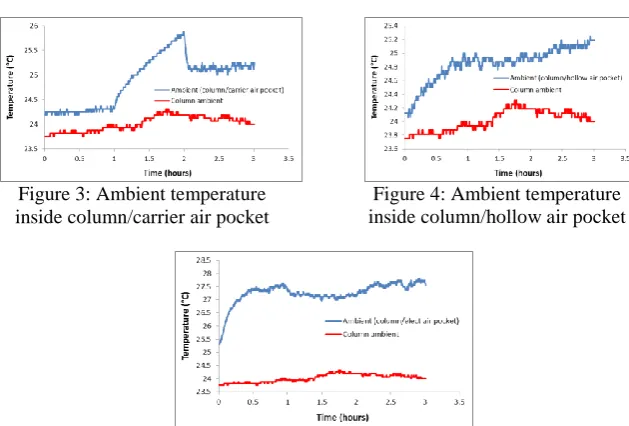
[image:6.595.154.335.176.272.2]later inside the suspected air pockets (in italics). Figure 3, Figure 4 and Figure 5 show, in blue, the local ambient changes detected by these new temperature sensors. The original measured column ambient temperature is also plotted, in red, to show the differences between ambient temperatures.
[image:7.595.85.400.332.545.2]Figure 2: Position of the ambient sensors around the machine
Figure 3: Ambient temperature inside column/carrier air pocket
Figure 4: Ambient temperature inside column/hollow air pocket
Figure 5: Ambient temperature inside column/elect air pocket
increase can be observed inside the column/elect air pocket during the stabilization period which is suspected to be the heat from the electrical cabinet and the cables being confined when the drives were energised during the machine stabilization phase (first hour). It can also be observed that the initial temperature had a large magnitude difference compared to the initial temperatures of other air pockets and the outside column environment.
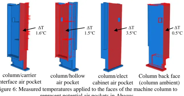
Previously the whole column was simulated with a constant ambient (sink) temperature in Abaqus. However, the above plots confirm that ambient temperature around the column is not constant. The local temperature change was selected from each plot and applied to the respective column sides as sink temperature. The column/carrier face was simulated with a temperature of 25.35°C considering that approximately 1.6°C temperature change occurred at that face from the start of the test (23.75°C surface temperature measured at the column). Similarly the inside face of the column was simulated with 25.25°C considering approximately 1.5°C temperature change and the column/Electrical cabinet face was applied with 27.25°C considering approximately 3.5°C temperature change. Figure 6 show the column faces where ambient magnitudes obtained from the new test were applied.
column/carrier interface air pocket
column/hollow air pocket
column/elect cabinet air pocket
[image:8.595.93.415.302.470.2]Column back face (column ambient) Figure 6: Measured temperatures applied to the faces of the machine column to
represent potential air pockets in Abaqus
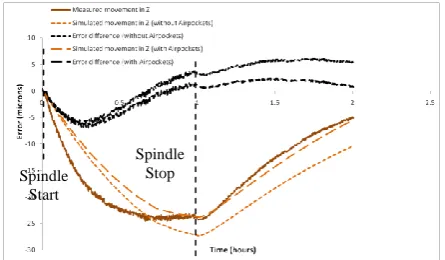
The simulation was repeated and Figure 7 show the correlation results for the Z-axis where a comparison can be made between the profiles with and without considerations to air pockets. Importantly, in the Z -axis direction an improved correlation of 62% was achieved compared to around 45% for the simpler model. The residual error remained is less than 10µm in magnitude. Figure 8 is the visual representation of the simulated deformation of the machine.
ΔT 1.6°C
ΔT 1.5°C
ΔT 0.5°C ΔT
Figure 7: Z-Displacement profiles correlation (8000rpm)
Figure 8: Simulated visual representation of deformation of the machine due to internal heating
2.2 Analysis of individual air pockets
This section details simulation-based analysis for each air pocket. The aim is to distinguish between the nature of the existence of air pockets with respect to their significance toward affecting the overall thermal performance of the machine. In this case study, all air pockets were considered as rectangular areas, although this is a justifiable simplification. Since the consideration of all air pockets in the FEA model improved the correlations of the Z-axis [9], at this stage it is important to note the distinction of each air pocket towards overall improvement of results for which each air pocket is now individually analysed. This is important analysis when undertaking error avoidance, to design out the cause of the error, or during development of thermal compensation to ensure the correct locations are monitored. Simple methods, such as improving ventilation, can be inherently more stable than implementing sophisticated and specialized compensation.
Spindle Start
Spindle Stop
Column
Carrier
Spindle
Test mandrel
Table
Base Original machine
Figure 9: Individual air pocket towards the overall correlation improvement
[image:10.595.108.387.85.224.2]The results shows that without the consideration of air pockets in the FEA, the model results showed excessive displacements during the heating cycle compared to the measured results. To a lesser extent, the cooling cycle results in the FEA also show deviation in amplitude. It is obvious from results that the column/carrier air pocket had the most effect and caused excessive bending in the column, which in effect created an angle, or out-of-squareness of the whole spindle-carrier structure. This effect better matched the measured cooling cycle profile but also brought the overall magnitude of the Z displacement closer to the measured. In comparison, the rest of air pockets individually improved the overall performance to a lesser extent. Table 1 shows the correlation improvement from inclusion of air pockets.
Table 1: Correlation improvements Air pocket Correlation improvement No air pocket 45%
column/elect 47% column/hollow 46% column/carrier 54% All pockets 62%
3
Conclusions
This paper explains the behaviour of air pockets inside the structure of a machine tool and their effect on the overall machine thermal performance. An improvement in the correlation of results between the measured and the FEA simulated results was achieved by including the effect of air pockets in the FEA model. Correlation result from a spindle heating test was improved from less than 45% to 62% in the Z-axis with spindle running at 8000rpm. Later, each air pocket was analysed individually to understand their significance on the overall correlation improvement. Perhaps counter intuitively, the most significant pocket was between the column and the carrier.
It can be stated that error avoidance by good design to counter the effect of air pockets is recommended where convenient. However, in cases where avoidance is not possible, air pocket behaviour must be considered during the development of any thermal compensation model to improve their predictability.
4
References
1. Hao, W., Z. Hongtao, G. Qianjian, W. Xiushan, Y. Jianguo, Thermal error optimization modeling and real-time compensation on a CNC turning center. Journal of Materials Processing Technology, 2008. 207(1-3): p. 172-179.
2. Du, Z.C., et al., Modeling approach of regression orthogonal experiment design for the thermal error compensation of a CNC turning center. Journal of Materials Processing Technology, 2002. 129(1-3): p. 619-623.
3. Kim, S.K. and D.W. Cho, Real-time estimation of temperature distribution in a ball-screw system. International Journal of Machine Tools and Manufacture, 1997. 37(4): p. 451-464.
4. Huo, D., et al., A Novel FEA Model for the Integral Analysis of a
Machine Tool and Machining Processes. 2004. p. 45-50.
5. Mayr, J., et al., Thermal issues in machine tools. CIRP Annals - Manufacturing Technology, 2012. 61(2): p. 771-791.
6. Longstaff, A.P., S. Fletcher, and D.G. Ford, Practical experience of thermal testing with reference to ISO 230 Part 3, in Laser Metrology and Machine Performance VI, D.G. Ford, Editor. 2003, WIT Press: Southampton. p. 473-483.
7. Fletcher, S., A.P. Longstaff, and A. Myers, Flexible modelling and compensation of machine tool thermal errors, in 20th Annual Meeting of American Society for Precision Engineering. 2005: Norfolk, VA. 8. Mian, N.S., et al., Efficient estimation by FEA of machine tool
distortion due to environmental temperature perturbations. Precision Engineering, (in press).