Knowledge based Contour Line
Reconnection Techniques
Mohan P Pradhan
Dept. of CSE, SMIT, SMU,Sikkim, India.
M K Ghose
Dept. of CSE, SMIT, SMU,Sikkim, India.
Pooja S Rai
Dept. of CSE, SMIT, SMU,Sikkim, India.
Nilanjan Mukherjee
Dept. of CSE, SMIT, SMU,Sikkim, India.
ABSTRACT
Contour line extraction from a topographical map is an integral part of Geographical Information System. Traditional technique for contour line extraction include manual digitization, this is a time consuming, tedious and a costly process. In addition the effectiveness of the result highly relies on the ability and skill of the researcher responsible for the same. To aid research initiatives these extraction process can be fully automated. In a typical topographical map in addition to the contours there are several other features represented such as point features (for e.g. Location), linear features (for e.g. river, road, contour etc.) and area (for e.g. reserved forest) features to name a few. These identifiable features are represented in different color codes for ease of visual interpretation. In order to extract these features of interest, color based segmentation process can be implemented and the basis for the segmentation can be set as the digital value referring the color in which the object is represented. Firstly, Segmentation process highly depends on the ability of the researcher in selecting the digital number representing a feature i.e. selection of improper range leads to improper classification. Secondly, Segmentation process generally fails to classify those digital numbers that are located at the point of overlapping of features such as a river running across the contour. Both these causes would lead to generation broken features. Knowledge based efficient reconnection techniques can be devised for overcoming the same. This research work aims at developing various techniques for reconnecting broken contour lines and compare their performance based on their ability to determine the search space for locating the extension point and then its ability to reconnect.
Keywords
Topographic map, Contour, Binary image, Reconstruction, Leech, Water flow, Wiper.
1.
INTRODUCTION
In Topographic maps host various overlapping features of interest concerning landscape, geographic information, natural and man-made features. It contains information related to roads, contours, landmarks, land covers and rivers etc. These features of interest play a pivotal role in inferential studies. Contour lines are integral part of topographic map; this feature is used in creation of DEM (Digital Elevation Model) and DSM (Digital Surface Model). Contour lines can be manually extracted but the integrity of results obtained is highly dependent on the skills of the researchers. In order to
overcome the lags of the manual digitization procedures, automated procedures can be developed to identify these features.
Automated digitization process capable of identifying features requires the aid of initial color segmentation process. Color segmentation is the process of highlighting only significant purpose specific feature of interest from the reference map while hiding the rest. The accuracy of segmentation process depends on its ability in segmenting a digital number into significant or insignificant class. If the digital number representing a feature is spread over a large range than the unwanted or insignificant digital number may also be segmented into a particular class. As a result the segmented data would represent significant as well as insignificant digital numbers i.e. errors. In-order to overcome this typical problem it becomes very essential to narrow the range of values that will be send as a basis to the segmentation algorithm. Narrowing of the range may lead to non selection of significant digital numbers that may be at a larger deviation from the range.
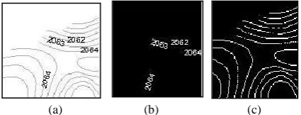
(a) (b) (c)
Figure 1: (a) Topographic Sheet (b) Segmented text (c) segmented contour (broken)
Segmentation process also fails to classify point of overlapping features as a result of change in digital value at the point of intersection. These two problems highlighted above are the main causes leading to broken contour lines.
So, to eradicate this problem knowledge based automated techniques can be designed that takes in segmented data which contains broken features and create a reconstructed feature for the same.
[image:1.595.322.535.460.541.2]search space, greater will be its efficiency and effectiveness as it would quantitatively require less time.
Any reconstruction algorithm capable of connecting broken line should be capable of
determining the segment
determining the terminating coordinate identify the extension point
reconstruct the line
Existing techniques take into consideration the various morphological aspects of contours. One such aspect is the gradient. In this technique basically the gradient orientation of the contours are determined and then nearest possible end points that can be matched for reconnection following the gradient are identified and connected with the help of a curve [6]. A typical problem that may be associated with reconnection algorithms is that the reconnection may not be smooth. So in-order to overcome that a smooth curve can be placed in between broken contours using Bezier curve or Hermite interpolation [6].
(a) (b)
Figure 2: (a) broken contour (b) improper reconnection
[image:2.595.67.245.335.430.2]Other aspect that can be used for reconstruction is the medial axis. Medial axis of a curve is a curve that contains a set of points. Where in each point has at least two points on the curve that are at equal distance from the point. It can be possible used in-order to reconnect a broken contour [2].
Figure 3: medial axis (in red) created between the two contour lines marked in black.
2.
RELATED WORK
Extracting and reconstructing contour map from the topographic sheet is challenging problem. Many research have carried out in past but a completely automatic map processing technique is still remains an open problem as most of the features are overlaid on top of the another one. Shimada et al. [1] suggest a multi-agent system to solve the problem of contour line reconstruction where each tracing agent is used to follow a specific contour. D. Xin et al. [5] also use
mathematic morphology to filter the binary image, a set of key points was extracted using the c-means algorithm, which were later used in GGVF (Generalized gradient vector flow) snake model used for reconstructing broken contour lines. S. Salvatore et al. [6] have used global topology of topographic maps to extract and reconstruct the broken contours based on two computational geometry concepts: Voronoi diagrams and Delaunay triangulations. The method is inspired from the previous work of [2, 3] focus on the reconstruction of contour lines using a method based on the gradient orientation field of the contours. Ghircoias and Brad [7] have proposed a framework for semiautomatic processing of scanned maps, extracting the contour lines vectors and building a digital elevation model out of it. They have used Amenta reconstruction method [2] for connecting broken contour lines. Gul and Khan [8] have proposed a method for automatic extraction of contour lines using adaptive thresholding method, and the broken lines are joined using curve fitting technique where the best candidate for connection us determined by analyzing the Euclidean distance. Hancer and samet [9] have proposed an advanced reconnection of contour lines extracted from scanned topographic maps using the parabolic directions and back tracing.
3.
METHODOLOGY
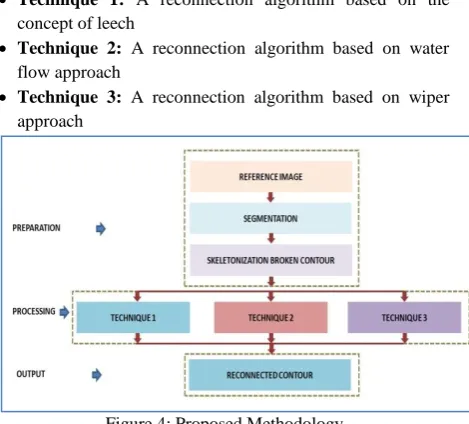
This research work aims at developing various techniques for reconnecting broken contour lines and compare their performance based on their ability to determine the search space for locating the extension point and then its ability to reconnect. This works introduces three new algorithms based on knowledge of natural sciences for reconnecting broken lines.
Technique 1: A reconnection algorithm based on the concept of leech
Technique 2: A reconnection algorithm based on water flow approach
Technique 3: A reconnection algorithm based on wiper approach
Figure 4: Proposed Methodology
3.1 Technique 1: A reconnection algorithm based on the concept of leech
[image:2.595.316.551.473.685.2] [image:2.595.125.208.527.606.2]to the other by attaching and detaching their suckers. They can crawl as well as swim. A leech can vary the distance covered per hop by either flexing or relaxing their muscles. A leech makes movement towards the prey either using it ability of sense and taste or vibrations created due to the movement of prey.
While designing this procedure the knowledge used from leech was to expand the search space for determining the extension point starting from a given point. This technique tries to expand the search space until certain limit is not reached or the extension point is not encountered. Initially the leech start the process with minimum distance of one and search for the extension point, if determined then reconnection is done else as a realization of muscle flexes the distance is incremented by one and the process repeats. The following representation explains how this proposed procedure progresses. Consider one’s in figures represents significant values that represents pixels of a line where as zeros are non significant values.
In this technique in-order to traverse the data set a Spiral Traversal Technique is used rather than using the traditional row column technique. Spiral traversal technique traversal technique is based on spiral model that exhaust row column in sequence either in clock wise and anti clock wise direction till the center coordinate is not reached.
On observing the figure it can be found that the line is broken. Now reconnection of this line has to be done. First the line is traversed to determine the intermediate termination coordinate for locating the breakage, once breakage is determined a leech is placed there in-order to determine the search space. (Figure 5)
Figure 5:- Broken Contour Line
Firstly the search space is determined using one pixel width distance. Figure 6 shows the first step of determining the search space.
Figure 6:- Search space with one width As extension point cannot be
determined with a distance of one pixel, now the process repeats again using two pixel width distance. Figure 7 shows the second step of determining the search space.
Figure 7:- Search space with two width
As extension point cannot be determined with a distance of two pixels, now the process repeats again using three pixel width distance. Figure 8 shows the third step of determining the search space.
Figure 8:- Search space with three width
As extension point is determined now with a three pixel width distance the process of connecting these to point should be initiated. The intermediate points between the point where the leech was placed and the extension point are then considered as part of the line. After reconnecting the line the leech would traverse the line until next breakage is determined or the terminating coordinate is reached. (Figure 9)
Figure 9:- Extension point determined and reconnected
This process tries to determine the possible extension point taking into consideration first eight neighbors, then 16 neighbors and so on. Lack of this algorithm is that it does not narrow down the search space for determining the extension point considering all possible neighbors to be equally likely. The termination point for this algorithm can be taken as a leech that extends to the maximum of inter- contour distance.
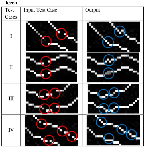
Table 1. Contour Reconstruction based on the concept of leech
Test Cases
Input Test Case Output
I
II
III
IV
3.2 Technique 2: A reconnection algorithm based on water flow approach
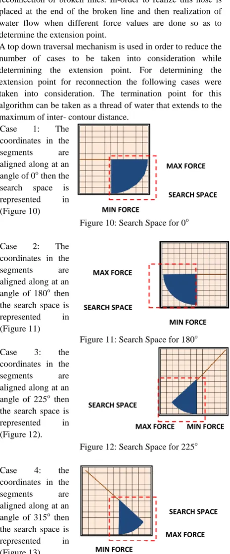
[image:3.595.306.549.445.695.2]interest can be covered. If maximum force is applied then the continuous thread of liquid will retain the direction for certain period of time and then circum to the effect of gravity. If minimum force is applied then the continuous thread of liquid will vertically drop to the ground as an effect of gravity. If intermediate force is applied then the continuous thread of liquid would follow a path between the paths traversed when minimum and maximum force is applied. This knowledge can be used in-order to possibly determine a search space for reconnection of broken lines. In-order to realize this hose is placed at the end of the broken line and then realization of water flow when different force values are done so as to determine the extension point.
A top down traversal mechanism is used in order to reduce the number of cases to be taken into consideration while determining the extension point. For determining the extension point for reconnection the following cases were taken into consideration. The termination point for this algorithm can be taken as a thread of water that extends to the maximum of inter- contour distance.
Case 1: The coordinates in the segments are aligned along at an angle of 0o then the
search space is represented in (Figure 10)
[image:4.595.317.522.69.179.2]O
Figure 10: Search Space for 0o
Case 2: The coordinates in the segments are aligned along at an angle of 180o then the search space is represented in (Figure 11)
Figure 11: Search Space for 180o Case 3: the
coordinates in the segments are aligned along at an angle of 225o then the search space is represented in (Figure 12).
Figure 12: Search Space for 225o
Case 4: the coordinates in the segments are aligned along at an angle of 315o then the search space is represented in (Figure 13)
Figure 13: Search Space for 315o
Case 5: the coordinates in the segments are aligned along at an angle of 270o then the search space is represented in (Figure 14)
Figure 14: Search Space for 270o
Table 2. Contour Reconstruction based on water flow approach
Test Cases
Input Test Case Output
I
II
In order to reduce complexity of implementation only one of the ends of a broken contour is taken under consideration for expansion.
Technique 3: A reconnection algorithm based on wiper approach
Wipers are cleaning systems installed in a vehicle for removing unwanted elements from the pane so as to maintain visibility while navigating it. Generally vehicles have one or two wipers installed for cleaning. In cases where two wipers are installed the wipers cleans the area without obstructing the workability of the other wiper i.e. each wiper has a degree of freedom defined and inter wiper distance defined that governs its movement. Designing a wiper and defining its degree of freedom and specifying length would be definitely applicable to the situation where broken lines are to be reconnected with it segment. Movement of the wiper can be used for the determination of the segment to be reconnected. Here the degree of freedom of the wiper defines the search space for possible reconnection point.
A top down traversal mechanism is used in order to reduce the number of cases to be taken into consideration while determining the extension point. For determining the extension point for reconnection the following cases were taken into consideration. The termination point for this algorithm can be taken as a wiper that extends to the maximum of inter- contour distance.
MAX FORCE
MIN FORCE SEARCH SPACE
SEARCH SPACE MAX FORCE MIN FORCE
SEARCH SPACE
MAX FORCE
MIN FORCE
MAX FORCE
MIN FORCE
SEARCH SPACE
MAX FORCE MIN FORCE
[image:4.595.55.288.185.746.2] [image:4.595.310.546.203.363.2]Case 1: the coordinates in the segments are aligned along at an angle of 0o then the search space is represented
in (Figure 15) Figure 15: Search Space for 0o
Case 2: the coordinates in the segments are aligned along at an angle of 180o then the search
space is represented
in (Figure 16) Figure 16: Search Space for 180
o
Case 3: the coordinates in the segments are aligned along at an angle of 225o then the search space is represented in (Figure 17)
Figure 17: Search Space for 225o
Case 4: the coordinates in the segments are aligned along at an angle of 315o then the search space is represented in (Figure 18)
Figure 18: Search Space for 315o Case 5: the
coordinates in the segments are aligned along at an angle of 270o then the search space is represented in (Figure 19)
[image:5.595.52.303.71.548.2]Figure 19: Search Space for 270o In order to reduce complexity of implementation only one of the ends of a broken contour is taken under consideration for expansion.
Table 3. Contour Reconstruction based on wiper approach
Test Cases
Input Test Case Output
I
II
4.
CONCLUSION
All three techniques implemented for reconnecting broken contour lines efficiently reconnects by determining the search space for locating the extension point. Technique 1 based on concept of leech determines the search space for locating the extension point by iteratively growing the search space by one until and unless extension point is not detected. The limitation of this technique is that it does not partition the search space. This technique can be improvised by also considering sensory ability of the leech to locate a prey along with ability to flex. Technique 2 based on the concept of water flow tries to determine variable sized search space for locating the extension point by taking into consideration certain force and radius. The limitation of this process is that it does not consider any point that is above the continuous thread of water when maximum force is applied. Technique three based on wiper determines the extension point by realizing a wiper placed at the point from where extension point is to be determined. Considering certain radius and certain degree of freedom (angle) it tries to locate the extension point. This technique considers spaces at the side of the reference axis for determining search space.
The advantages of these techniques on other previous techniques are that
these techniques relies very less on the knowledge regarding the state of other contours in the dataset these techniques do prevent cross over between the
different broken lines as there is a restriction on the number of iterations
these techniques can be further enhanced for reducing the search space by including knowledge of spline curves.
5.
REFERENCES
[1]. Shimada, S., Maruyama, K., Matsumoto, A., Hiraki, K., Agent-based parallel recognition method of contour lines, Proc. of Third international Conference on Document Analysis and Recognition, Vol. 1, IEEE Computer Society, Washington, DC, pp. 154, 1995.
[2]. N. Amenta, M. Bern, D. Eppstein: The Crust and the Beta-Skeleton: Combinatorial Curve Reconstruction, Graphical models and image processing, Vol. 60, No. 2, pp. 125-135, 1998.
[3]. Du, J., Zhang, Y., Automatic extraction of contour lines from scanned topographic map, Proc. of International Symposium on Geoscience and Remote Sensing, Vol. 5, pp. 2886-2888, 2004.
[4]. S. Salvatore, P. Guitton, Contour Lines Recognition from Scanned Topographic Maps, Journal of Winter School of Computer Graphics, Vol.12, No.1-3, 2004.
[5]. Xin, D., Zhou, X., Zhenz, H., Contour Line Extraction from Paper-based Topographic Maps, Journal of Information and Computing Science, Vol. 1, pp. 275– 283, 2006.
[6]. J. Pouderoux, S. Spinello: Global Contour Lines Reconstruction in Topographic Maps, Proc. of the Ninth international Conference on Document Analysis and
SEARCH SPACE
SEARCH SPACE
SEARCH SPACE
SEARCH SPACE
[image:5.595.45.288.632.766.2]Recognition, Vol. 02, ICDAR, IEEE Computer Society, Washington, DC, pp. 779-783, 2007.
[7]. Ghircoias, T., Brad, R., A New Framework for the Extraction of Contour Lines in Scanned Topographic Maps, Intelligent Distributed Computing, IV Studies in Computational Intelligence, Vol. 315, pp. 47-52, 2010.
[8]. Gul, S.,Khan, M. F., Automatic Extraction of Contour Lines from Topographic Maps, Proc. of International
Conference on Digital Image Computing: Techniques and Applications, December 2010.