Titanium Alloy Welding Using
Middle Range Power Pulsed Wave Laser
2.
~ o h i d l * ~ ,
Z.
A.
ash id',
A.
wagirnanlsb,
M.N.H
~ a f a i ' * ~ a n d
E.A. ~ a h i r n ' . ~
'~dvanced Machining Research Group (AMRG),
Faculty of Mechanical and Manufacturing Engineering, Universiti Tun Hussein Onn Malaysia, 86400, Parit Raja, Batu Pahat, Johor, Malaysia.
Keywords: Titanium alloy, YAG laser, penetration depth
Abstract. Laser welding are well reported to be excellent in precision parts joining with high reputations in external finishing. However, the process in obtaining the best processing parameters is not an easy task. In the case of pulse wave laser, the parameter setting constrained by the laser
generator specification. Each laser parameters such as pulse width t,, pulse repetition rate f, and
average laser power P,, has relation which others. Increasing one parameter will directly decreases
the maximum value of other parameters. The limited applicable combination and rage of processing parameters make it difficult to obtain the optimized processing parameters. This study is conducted to investigate the influence of each lasing parameters on the welding penetration capability. The range of applicable parameters for titanium alloy sheet metal has been successfully clarified
Introduction.
The parameters involved in laser welding can be divided into two categories, laser parameters and machine parameters. The most commonly discussed laser parameters are laser power or laser energy, pulse repetition rate, pulse width, laser beam size and focus position whilst machine parameters are
such as travel speed, work piece geometry and irradiation angle.
The value of average power Pmg, pulse energy E, pulse repetition rate&, pulse width t, and peak
power
Ppk
are connected with one another. The relation between each parameter is shown inequation 1 and 2 where T is the time taken for each pulse cycle. Increasing one parameter will consequently lemmatize the other parameters applicable range. Each parameters give different effect to the welding characteristics.
In the case of welding penetration depth, peak power is the most influencing parameter. Penetration depth increases with peak power under constant pulse duration [I]. Increasing pulse repetition rate will effectively reduce the thickness of heat affected zone [2]. Increasing the pulse repetition rate will allows higher scanning speed with the same overlap area. This will consequently
produce narrow welding width, thin heat affected zone and less underfill depth [3]. Laser power plays
an important role in controlling the area of fusion [4]. It is crucially important to select a well balance value of laser power, pulse repetition rate and scanning speed to optimize welding quality. The combination of scanning speed and pulse energy could give significant influence on the type of welding; conduction or keyhole welding. The morphology and mechanical properties is largely
influenced by the total energy input per unit area [ 5 ] .
811 rights resewed. No part of contents of this paper may be reproduced or transmitted in any form or by any means without the written permission of TTP,
Experimental setup.
Laser head with focus distance and beam diameter of 160mm and 0.480mm was used to convey
the laser beam on to the work piece material. The materials with 1.8mm of thickness were cut into
25mm x 5 mrn and welded on a clamping device.
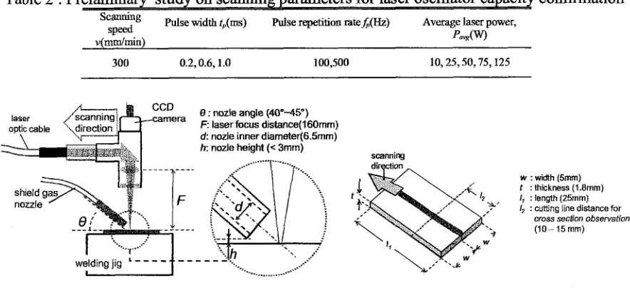
In the early study, the scanning parameters in Table 2 were determined based to the laser oscillator capacity shown in Table 1. The scanning speed and pulse repetition rate were determined with
conditions that the overlap area must be more than 50%. The result of the early study has led to the
new set of parameters. These parameters were used to focally analyze the influence of certain processing variables w i t h a smaller range value to obtain the optimized processing parameters.
Table 1 : Laser oscillator capacity
-
Items Minimum Maximum Unit
Value Values Average Laser Power, PmY? 300 W
peak Laser Power, P,,k
-
9 kW
Pulse Energy, E 56 J
M e Width, t,, 0.2 20 ms
[image:2.601.82.524.324.526.2]Pulse Reptition Ratef;, 1 1000 HZ
Table 2 : Pr confirmation
Scanning
S P ~ Pulse width t,(ms) Pulse repetition rateA(Hz) Avemge laser power,
v(mm/min) Pa@')
wqlding jig ' -
- - -
f- -
f3 : nozle angle (40'-45")
F: laser focus dislance(l60rnm)
d: node inner diarneter(6.5mm) h: node height (< 3mrn)
w : w'klth (5rnrn) t : thickness (1.8mrn)
I, : length (25rnrn)
I, : cutting line distance for
cross section observation
(10-15rnm)
Figure 1: Experimental setup and work piece schematic diagram
Preliminary study has been done to clarify the range of parameters applicable for welding process
of titanium alloy with thickness 1.8mm. Pulse repetition rate f, were set lower than middle range
(100Hz and less), to provide average laser power
P
,
,
and pulse width t, with larger modificationrange.
To obtain deep penetration welding beads, the influence of laser beam focus position has been
studied. It was found that the penetration at 1.5mm underneath the work piece surface shows better
result compared to the beam focusing on the top surface.
Further experiments were conducted to analyze the effect of processing parameters on the defect
of free deep penetration welding as shown in Table 3. Laser scanning was performed with focus point
of 1.5mm under the material top. Argon gas with flow rate 7Ymin was delivered using 6.5mrn inner
diameter nozzle with approximately 45" tilted and the distance of lOmm from the scanning point.
Table 3: Processing parameters selected
[image:2.601.85.485.730.777.2]Results and discussion.
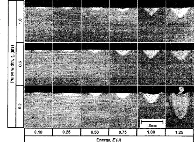
The study revealed that by employing the pulse width of l.Oms, at least 0.55 is needed to initiate
deep welding pool. Although increasing laser energy is effective to enhance penetration depth, there
is a limit where cracks and sputtering problems become too obvious. Scanning using 100Hz of pulse repetition rate and 1.255 of laser energy, it needs to be done with pulse width 0.6ms and above to avoid sputtering problem. Figure 2 shows the effect of energy and pulse width on welding depth. It shows that the applicable pulse width is between 0.6 and 1 .Oms while E is between 1.0 and 1.255. In
the case off, is 500Hz, the welding depth significantly decreases. By employing the lower
f,
of [image:3.595.138.459.225.459.2] [image:3.595.108.496.243.636.2]100Hz subsequently deeper welding depth can be obtained.
Figure
0.10 0.50 0.75 1.00 1.25
Energy, E(J)
Melted zone cross section view under different energy and pulse re
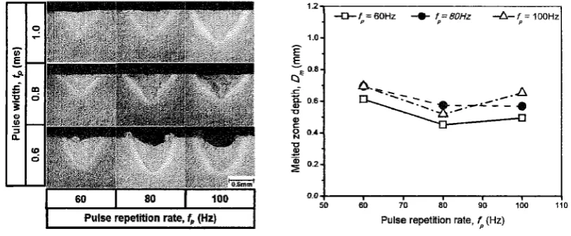
Figure 3: Comparison of melted zone depth created under 1 OOHz pulse
repetition rate and 3 0 0 d m i n scanning speed
Further experiment was conducted using the parameters listed in Table 3. In general, pulse
repetition rate ranging between 60Hz to lOOHz was insignificant in the changes of melted zone width and depth. In the case of pulse duration 0.6ms, melted zone depth increases steeply with the increase
1.1 1 2 -
+E=l.OOJ --t E=1.15J d - E = 1 . 2 5 ~
of pulse repetition rate. However the maximum melted zone depth was approki~ately equal to the
one crated using 0.8ms and 1 .Oms of pulse width.
Pulse width, 5 [ms)
1.0-
E .
E
2
O.3-f
0 6 -u
0 .
0 0.4-
- 0 .
-
-
% 0 2 -
0.0
0.5
0
-
2
#
I I I
Under 1.255 laser energy, scanning speed of 3 0 0 d m i n and pulse repetition rate of 100Hz, the melted zone depth on blank titanium alloy sheet reaches 0.7mm. Cross sectional views of the specimens revealed that the range of parameters was thoroughly applicable in actual welding. Although lower puke width could create deeper and sharp melted zone, the top surface conditions were unfavorable for sputtering and obvious overlap melted metal layers can be seen.
[image:4.595.99.506.161.329.2]Pulse repetition rate, fp (Hz)
Figure 4: Comparison of melted zone depth created under 1.253 laser energy and
3 0 W m i n scanning speed
Figure 4 shows the influence of different pulse repetition rate and pulse width on the melted zone geometry. The cross sectional of melted zones indicate that the pulse width needs to be larger in order to obtain clean welding beads. The peak power at pulse width of 0.6ms is assumed to be too high which initiate high pressure generation during each irradiation. By comparing the depth between three different pulse width, 0.8ms created shallow the melted zone. It is suggested that the difference in keyhole formation efficiency under differences peak power contributed to the variation of melted
zone depth. Smaller value of depth to width ratio of the melted zone indicates that the heat energy has
induced into the material and spread equally in radial direction under bigger pulse width. Reducing
the pulse width under the same energy will increase the peak power. This will consequently generates
higher expansion pressure in the melted area. Therefore, it creates the keyhole which could increase the laser absorption rate. However the time of thermal energy to be conducted into the material becomes shorter and it chilled before the next laser spark. The increment of laser absorption rate and reduction of thermal energy conduction time has contributed to shallow melted zone under 0.8ms pulse width.
Conclusions
Investigation on the influence of each parameter has been done started in broad range value to see
the melted zone changes tendency. Form the result, focus has been given to a small range of parameters seems to be applicable. In the case of middle range powered Nd YAG laser, it can be
concluded as bellow.
1. Scanning using lOOHz or less under 3 O W m i n scanning speed could only produce melted zone with maximum depth not more than 0.8mm on Ti6A14V.
2. Using larger pulse width is able to reduce the risk of sputtering problem. At least 1 .Oms is needed for clean and flat welding line creation.
3. Under a constant pulse width, increasing pulse repetition rate could moderately increase the melted zone depth.
Acknowledgement
This study is funded by Fundamental Research Grant Scheme research grant, VOT number 0730
from Ministry of Higher Education of Malaysia.
References:
[ l ] E. Akman, A. Demir, T. Cane1 and T. Smazc,elik, "Laser welding of Ti6A14V titanium
alloys," Journal of Material Processing Technology, vol. 209, pp. 3705-3713,2009.
[2] L. Shanjin and W. Yang, "An investigation of pulsed laser cutting of titanium alloy sheet,"
Optics and Laserss in Engineering, vol. 44, pp. 1067-1077,2006.
[3] X. Cao and M. Jahazi, "Effect of welding speed on butt joint quality of T i d A 1 4 V alloy
welded using a high-power Nd:YAG laser," Optics and Lasers in Engineering, vol. 47, pp. 123 1-1241,2009.
[4] E. A. Anawa and A. G. Olabi, "Using Taguchi method to optimize welding pool of dissimilar
laser welded components," Optics & Laser Technology, vol. 40, pp. 379-388,2008.
[5] A. Squillance, U. Prisco, S. Ciliberto and A. Astarita, "Effect of welding parameters on