scroll down to view the document itself. Please refer to the repository record for this item and our policy information available from the repository home page for further information.
Author(s): Gasser, Thomas; Palmer-Brown, Dominic; Xiao, David Title: Paradigm shift in PLC programming
Year of publication: 2009
Citation: Gasser, T., Palmer-Brown, D., Xiao, D. (2009) ‘Paradigm shift in PLC programming’ Proceedings of Advances in Computing and Technology, (AC&T) The School of Computing and Technology 4th Annual Conference, University of East London, pp.43-50
Link to published version:
PARADIGM SHIFT IN PLC PROGRAMMING
Thomas Gasser
1, Dominic PalmerBrown
2, and David Xiao
21
MST Systemtechnik AG, Airport Business Center 60 CH3123 Belp, Suisse
2
School of Computing, Information Technology & Engineering, University of East London
Abstract: In the programming of PLCSystems (Programmable Logic Controller) in building automation there are no vital changes over the past few years. Most user of PLCSystems in building automation do the programming in fbd (functional block diagram). The users normally start their projects with the programming of the PLCSoftware. After that the HMI (Human Machine Interface) or the SCADASystem (Supervisory Control And Data Acquisition) are added as subsequent Tasks. This paper present a new approach to a project, the approach is changed from a bottom up into a top down one. The starting point of a project is the plant diagram. The programming is done in the plant diagram. Template objects (e.g. for pumps) created with the object orientated paradigm are used to accomplish this task. The created PLCSoftware runs in a virtual machine on the PLCSystem and
thus will be reusable on PLCSystems of different manufacturers.
1. Introduction:
It is planned to develop a programming language for SCADASystems which is independent of PLCHardware manufacturers. The SCADASystem programming language should be a kind of a functional block language. This because it is much easier for people to work with functional blocks and do the programming graphically than with an abstract programming language. LabVIEW from National Instruments or MATLAB from the MathWorks are good examples for graphical programming tools. In IEC 6011313 Standard (IEC 2003) two graphical programming languages are defined, fbd and the ld (Ladder diagram). Ladder logic is the oldest programming language for PLC Systems. Programming in ld is done by copying the wiring diagram into the PLC System programming tool. Fbd consists of functional blocks which are connected together as it is done with logical gates. With the SCADA programming language,
the logic operations are created in a special programming mode while drawing the process charts. The programming will be according to the ISO 164843 Standard (ISO 164843). (Kandare, G et al 2003) offers an approach to PLCCode generation for real world problems. An abstract functional block diagram is used to generate st (Structured Text). St is also part of the IEC 611313 Standard and is similar to high level languages such as C++ or Java.
as a modelling tool (Thieme, J and Hanisch, J 2002) (Klein, S et al 2003). It has to be determined how a generic code generator can be realized which enables an easy implementation of a new PLCSystem. For this task, the principles of compiler development (Aho, A et al 2007) has to be used. It is essential, that only a small part of the generator, the backend, has to be changed if a new PLCSystem should be implemented. For this purpose it is essential to assess how data are stored in different PLCSystems. A prototype of the code generator has to be developed.
The source code produced by the code generator should be saved on various target systems in the same way (e.g. in data blocks or arrays) and run on a virtual machine. The virtual machine checks the logical operations repetively. If there are any changes of states in the logical operations, the respective code is executed. Suitable solutions have to be developed for an implementation of a virtual machine on a PLCSystem with the highest possible gain of performance. Virtual machines are covered in detail in (Smith and Nair 2005). Performance has to be tested for different PLCSystems.
1.1 Traditional approach:
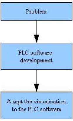
As shown in Figure 1 traditional approach the traditional approach in an building automation project stipulates, that first the software for the PLC is developed and as a subsequent task the visualisation is adapted to the PLC software.
1.2 New approach:
With the SCADASystem programming language a noval approach was chosen ( Figure 2 new approach). The PLC software has to be developed object oriented. The
whole engineering and the design of the plant diagrams is done with template objects. A huge amount of the PLCCode which runs the plant can be generated. The necessary connections between the TO' s (Template Objects) is done afterwards in il (Instruction list) or fbd. Il and fbd are parts of the IEC 611313 standard (IEC 2003). Currently the connection of the parameters have to be done in il or fbd. In the future the connections should be established direct in the plant diagram to replace the programming in the il or fbd.
To replace the last step in Figure 2 new
[image:3.595.342.467.353.559.2]approach, the programming in il or fbd, it has to be possible to create the PLC software direct in the plant diagram.
Figure 1 traditional approach
Figure 2 new approach
Figure 3 direct connections
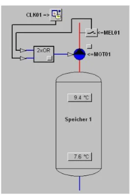
In the life cycle of a project the dependencies of an input parameter can change. To make a program modification as simple as possible, the logic TO' s should have a variable number of inputparameters. It have to be possible to add or remove connections and afterwards download the edited program to the PLC without stopping it.
[image:4.595.342.475.130.330.2]Example:
Figure 4 logic connections
2. Logical template objects:
To realize the programming of a facility on the plant diagram, logic template objects are necessary. One possible solution of an implementation of such template objects on a PLCSystem of SaiaBurgess is shown in the following section. The template objects have to be modelled according to the UML 2.0 standards (Kecher 2006). Some attempts has been made to use UML to generate PLCCode (Sacha, K 2005) (Lee, JI et al 2002).
3. Storage of the Data:
The connection data should be stored in appropriate data structures. The data structure used, depends on the used PLC System. In this section, a PLCSystem from SaiaBurgess is used for the example.
[image:4.595.107.222.326.522.2]are available with up to 16384 32bit registers. The data blocks from 0 up to 3999 can only store 383 32bit values. Because of hardware reasons the access to these data blocks is significantly slower than to the ones in the higher memory area. For this reason, the data blocks starting from 4000 should be used.
3.1. Example for an AND gating with four parameters on a SaiaBurgess PLC System:
In this section a possible solution for an AND gating with four parameters on a Saia Burgess PLCSystem is shown.
Table 1 AND gating example
Parameter Data Type Address
Conjunction input 1 Flag 1000
Conjunction input 2 Input 65
Conjunction input 3 Output 88
Conjunction result Flag 234
For the above example Table 1 AND gating example the data block would be generated as follows:
Table 2 Assembly of a datablock
Function 0x01
Number of Inputs 0x03
Res Type 0x01
Res Address 234
Res Logic 0x00
Par1 Type 0x01
Par1 Address 1000
Par1 Logic 0x00
Par2 Type 0x02
Par2 Address 65
Par2 Logic 0x00
Par3 Type 0x03
Par3 Address 88
Par3 Logic 0x00
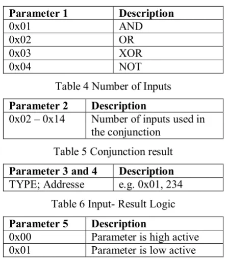
Parameter description:
[image:5.595.304.526.182.436.2]The coding of the parameters in the data block from Table 2 Assembly of a datablock is shown in the following section.
Table 3 Function codes
Parameter 1 Description
0x01 AND
0x02 OR
0x03 XOR
0x04 NOT
Table 4 Number of Inputs
Parameter 2 Description
0x02 – 0x14 Number of inputs used in
the conjunction
Table 5 Conjunction result
Parameter 3 and 4 Description
TYPE; Addresse e.g. 0x01, 234
Table 6 Input Result Logic
Parameter 5 Description
0x00 Parameter is high active
0x01 Parameter is low active
The conjunction result is stored in parameter 2 and 3 of the data block (Table 5 Conjunction result). Thus the position of the result is independent of the number of parameters. In Table 7 Data type codes a possible coding for the different data types is shown.
Table 7 Data type codes
Data type codes Datatype
0x01 Flag
0x02 Input
0x03 Output
4. Virtual machine on the PLC:
· process virtual machines
· system virtual machines
An example of a system virtual machine is Vmware. Vmware provides the user with an environment where a complete operating system (guest) can be installed and run on an other operating system (host). A process virtual machine deals with a single task. For this investigation only process virtual machines are of importance.
4.1. Process virtual machine:
A case in point for a process virtual machine is the java vm. The byte code produced by the java language processor is interpreted in the virtual machine as a single process. The source code can be interpreted in different ways (Smith and Nair 2005).
· Decodeanddispatch interpretation
· Indirect threaded interpretation
· Predecoding and direct threaded interpretation
· Binary translation
For an implementation on a PLCSystem only the first and the second are of importance because no transformation from one ISA (Instruction Set Architecture) into an other is made.
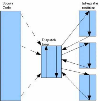
4.2. Decode anddispatch Interpretation:
[image:6.595.307.517.109.322.2]A decodeanddispatch interpreter is structured around a central loop that decodes an instruction and then dispatches it to an interpreter routine based on the type of instruction. This kind of interpretation involves a lot of branches, which can be a very time consuming task. There is an interpreter routine for every source instruction.
Figure 5 Decode and dispatch interpretation
4.3. Indirect Threaded Interpretation:
In the indirect threaded interpreter the central loop is omitted (Figure 6 Indirect threaded Interpretation). To every interpreter routine the necessary code to fetch and dispatch the next instruction is added.
[image:6.595.306.521.474.658.2]5. Code generator:
The SCADASystem programming language is a kind of a functional block language. The logic operations are created in a special programming mode while drawing the process charts. The conjunction data is saved in the project definition file. There are two kinds of conjunctionparameters, input and output parameters respectively. The parameters are stored as shown in Figure 7 Storage of connection parameters (e.g. PAR_IN):
Figure 7 Storage of connection parameters (e.g. PAR_IN)
The Code generator uses the data stored in the definition file to create a dependency tree. By means of the dependency tree the PLCCode will be generated. (Sacha, K 2005) shows a way to automatically generate code for PLCSystems. Unfortunately the PLCLanguage generated is ladder logic. Which is not the best choice for complex systems because of its limitations. Therefore st or il should be the languages generated.
6. Discussion:
With this futureoriented approach, for the first time it will be possible to accomplish all tasks in the realization of a project in building automation with one tool using the object orientated paradigm in a top down approach without any dependency on the PLCHardware.
The user of the SCADASystem fbd will be able to respond to the wishes of the customer regarding the PLCHardware without problems. Projects once build with the SCADASystem fbd can be used with hardware of different manufacturers. The user only has to change the PLC Manufacturer in his project and to regenerate the code. In this way the user easily can build up libraries of plant templates and achieve a much faster time to marked with his products.
The fact that the SCADASystem fbd will not be developed by a PLCManufacturer ensures that no economic interests will reduce the independency from the PLC Hardware
7. Summary:
The merging together of SCADA, HMI development and PLC programming will lead to a more natural way in programming PLCSystems. In a first step the user draw his plant diagram with template objects (TO' s) and afterwards bind the template objects on the plant diagram together. With this approach the user only have to cope with one softwaretool. The independency from the PLC hardware will be an additional alleviation for the user. So this investigation will help to intensify the cooperation between PLCManufacturers and SCADA System developers.
8. Acknowledgements:
9. References:
Alfred Friedrich, M. F. (2006). Strukturierte Programmierung von Ablauf und Zeitplansteuerungen. expert Verlag, Renningen.
Alfred V. Aho, Monica S. Lam, Ravi Sethi, Jeffrey D. Ullman (2007). Compilers Principles, Technique & Tools. Addison Wesley.
BrandtPook, H., Korzen, B., Boidol, J. & Peyn, H. (2001). Application development in timecritical projects.
WIRTSCHAFTSINFORMATIK,43, 247.
Christoph Kecher (2006). UML 2.0. Das umfassende Handbuch. Galileo Press Bonn. Eden, A. (2002). A theory of objectoriented design. INFORMATION SYSTEMS FRONTIERS,4, 379 391.
Frank, H. & Eder, J. (1999). Towards an automatic integration of statecharts.
CONCEPTUAL MODELING ER'99, 1728,
430 444.
Gaspar, C. & Franek, B. (2006). Tools for the automation of large distributed control systems. IEEE TRANSACTIONS ON NUCLEAR SCIENCE,53, 974 979.
Guida, G. & Lamperti, G. (2000). A methodology for requirements analysis of advanced humansystem interfaces. IEEE TRANSACTIONS ON SYSTEMS MAN AND CYBERNETICS PART ASYSTEMS AND HUMANS, 30, 298 321.
Iain D. Craig (2004). Virtual Machines. Springer, London.
Ian Sommerville (2001). Software Engineering. AddisonWesley.
IEC (2003). IEC 611313 Programmable controllers Part 3: Programming languages.
ISO (2005). ISO 164843: Systeme der Gebäudeautomation (GA)Teil3: Funktionen.
Kandare, G., Godena, G. & Strmnik, S. (2003). A new approach to PLC software design. ISA TRANSACTIONS,42, 279 288. Kawada, T., Nakamichi, K., Hisano, N., Kitamura, M. & Miyahara, K. (2006). Cell phone based assistance for waterworks/sewage plant maintenance.
WATER SCIENCE AND TECHNOLOGY,
53, 245 252.
Klein, S., Frey, G. & Minas, M. (2003). PLC programming with signal interpreted Petri nets. APPLICATIONS AND THEORY OF PETRI NETS,2679, 440 449.
Konaka, E., Mutou, T., Suzuki, T. & Okuma, S. (2005). Optimal design of sensor parameters in PLCbased control system using mixed integer programming. IEICE TRANSACTIONS ON FUNDAMENTALS OF ELECTRONICS COMMUNICATIONS AND, E88A, 818 824.
Lee, J., Chun, S. & Kang, S. (2002). Virtual prototyping of PLCbased embedded system using object model of target and behavior model by converting RLLtostatechart directly. JOURNAL OF SYSTEMS ARCHITECTURE, , 17 35.
Morris, D., Green, P. & Barker, R. (1995). ENGINEERING THE SOFTWARE IN SYSTEMS. SOFTWARE ENGINEERING JOURNAL, 10, 253 265.
Robert Sedgwick (1992). Algorithmen in C++. AddisonWesley.
Sacha, K. (2005). Automatic code generation for PLC controllers. COMPUTER SAFETY, RELIABILITY, AND SECURITY, PROCEEDINGS, 3688, 303 316.
Smith, J. E.et al. (2005). Virtual Machines. Elsevier Inc, Amsterdam.
The Institution of Electrcal Engineers (1995). Colloquium on: Application of advanced PLCSystems with specific experiences from water treatment. , 1995/112, .
Thieme, J. & Hanisch, H. (2002). Model based generation of modular PLC code using IEC61131 Function Blocks. ISIE 2002: PROCEEDINGS OF THE 2002 IEEE
INTERNATIONAL SYMPOSIUM ON
INDUSTRIAL ELECTRONICS, VOLS 14, , 199204.
Veryha, Y., Jalowicki, S. & Nidamarthi, S. (2006). Efficient Control Engineering with PLC vendor independent programming and parameterization.
Young, K., Piggin, R. & Rachitrangsan, P. (2001). An objectoriented approach to an agile manufacturing control system design.
INTERNATIONAL JOURNAL OF
ADVANCED MANUFACTURING