Optimal Allocation and Sizing of Multi DG for
Distribution Networks
G. Pavan Kumar1, M. Kishore Kumar2
1, 2
Academic Consultant, Electrical & Electronics Engineering, YSR Engineering College of YVU, Proddatur, Andhra Pradesh, India
Abstract: High levels of penetration of distributed generation (DG) are a new challenge for traditional electric power systems. Power injections from DG’s change network power flows, modifying energy losses and voltage profile of the system. Proper locations and sizing of DG’s in power systems are extremely important in order to obtain maximum potential benefits. This paper proposes a multi-objective index-based approach for optimally determining the size and location of multi distributed generation (DG) units in distribution systems based on genetic algorithms in order to minimize the technical aspects like energy losses, improvement of voltage levels. In this paper Primitive impedance based distribution load flow is used for distribution systems load flow and takes the IEEE 38-bus test system to validate the methodology. Analysis and simulations indicates that installation of DG results in active and reactive power loss reduction and voltage improvement.
Keywords: Distributed generation, distribution network, genetic algorithm.
I. INTRODUCTION
Distributed generation (DG) is not a new concept but it is an emerging approach for providing electric power in the heart of the power system. It mainly depends upon the installation and operation of a portfolio of small size, compact, and clean electric power generating units at or near an electrical load (customer). Till now, not all DG technologies and types are economic, clean or reliable. A Smart Grid delivers electricity from suppliers to load centres using the technology to save energy, reduce price and increase reliability and transparency. Such a new electricity network is being promoted by many governments as a way of addressing energy independence. Distributed energy resources (DER) are tiny sources of generation and/or storage that are connected to the Distribution System at load centres. For low levels of discernment, DER does not have a large consequence on system pattern as long as they have proper protection at the point of interconnection. A Smart Grid has the potential to have large and flexible sources of DER.
Other outline issues identified with the capacity of a Distribution System to work as an Electrical Island, the capacity of a Distribution System to diminish ideal Power Flow requirements, and the capacity of DER to work in conjunction as a virtual Power Plant. Power market is developing colossally and quickened specialized advances have prompted plant's size and unitary limit cost decreases. These patterns advance private cooperation in limit development in a market-situated industry association. Moreover, establishment of little generators found near the loads, may give greater adaptability to the power advertise. Establishment of Dispersed Generation (DG) at non-ideal spots can bring about an expansion in framework misfortunes, reconfiguration of assurance conspire, voltage issues, and so on...
The points of interest by the presentation of DG units at ideal spots Improves the voltage profile and lessens the losses, Back-up emergency power, Peak shaving, Grid support, behaves as premium power. Variety of methodologies and tools has been created to distinguish ideal spots to introduce DG limit and its size. These philosophies depend on analytical methods, optimization techniques or heuristic methods. A large portion of them locate the ideal assignment and size of DG so as to diminish losses and enhance voltage profiles. Others incorporate the cost of vitality not provided and a couple dives deep in working considerations. Improvement strategies ought to be utilized for deregulation of the power industry, taking into account the best location of the dispersed generation (DG). The headway in innovation and a want of the clients for modest and efficient electric power has prompted an expanded enthusiasm in distributed generation. The issues identified with reliability and maintenance has impeded the penetration of DG resources and in distribution systems.
making methods. This optimization permits the optimal location of generators to be found so that real and reactive power losses in a present distribution network are reduced, and investments for electric grid expansion, due to the increase of the energy demand can be deferred or reduced.
The paper is organized as follows: Section II presents a algorithm development of proposed primitive impedance load flow technique. Section III presents a short review of the different methodologies and tools reported in the literature to find (or evaluate) places and sizes of DG in a distribution network. Section IV presents the specific problem formulation and GA implementation. Section V presents the simulation results and analysis. Section VI concludes. Results show that installation of Multi DG results in reduction of real and reactive power loss and voltage improvement. Loss reduction is reached when DG is installed in remote bus bars.
II. ALGORITHMDEVELOPMENTOFPROPOSEDLOADFLOW
Topological and Primitive Impedance based Distribution Load Flow Method for Radial Distribution Systems is an effective load flow which calculates the voltage vectors instead of separate calculations of voltage magnitude and phase angle. The newer load flow used involves sparsity vector and pathline and ipath vectors and does not have any need of trigonometrically functions which causes faster convergence.
A few have proposed a load flow method by writing an algebraic equation for bus voltage magnitude. The Gauss Implicit Z-matrix method is one of the most commonly used methods, however this method does not effectively exploit the radial structure of the Distribution System and therefore, needs to find the solution of a set of equations of the order of number of buses. Some of the researcher’s proposed special load flow techniques based on Topological characteristics of Distribution Systems. In the paper by Jen-HaoTeng, [2] “A Direct Approach for Distribution System Load Flow Solutions,” for a balanced Radial Distribution System has been proposed. The proposed Load Flow Algorithm requires formation of Bus-Injection to Branch Current (BIBC) matrix with 1’s & 0’s as elements and Branch-Current to Bus-Voltage (BCBV) matrix with primitive impedances as elements & Distribution Load Flow (DLF) matrix. DLF matrix is obtained as product of (BCBV) and (BIBC) matrices. These three matrices require large memory space when the proposed method applied for bigger Distribution System. Further, these three matrices contain more number of zero elements and hence memory space is not utilized economically, especially for large size Distribution Networks. Another negative aspect of it is that, to obtain a Load Flow Solution it needs direct multiplication of BCBV & BIBC matrices and DLF & ‘current Injection column vector’ matrices. This requires sufficiently large CPU time.
The main aim of this algorithm is to develop a new formulation for load flow method, which exploits the topological characteristics of a balanced Distribution System. A unique ‘Effective data structure’ is proposed to identify all those lines that are traced in the path connecting the ‘feeding bus’ and any ‘selected buses. This feature acts as a potential support in solving the Distribution Load Flow equations derived in terms of primitive impedances of the lines. Unlike to other traditional methods, the proposed approach does not require any LU Decomposition or Bus admittance matrix. Compared to the other algorithms, the proposed method does not require any direct matrix multiplications and no need of formation of BIBC, BCBV and DLF matrices. It only requires the calculation of diagonal elements of DLF matrix in terms of the primitive impedances of the lines. In this proposed algorithm, sparsity technique is used to identify the adjacent buses and adjacent lines of any selected bus of the system. The proposed distribution load flow method is robust, time-efficient and needs very less memory even for a large size Distribution System. Consider a sample radial Distribution System as shown in the Fig-I for the formation of the above matrices.
For the system shown in Fig-1 apply Kirchhoff’s Current Law (KCL), the branch currents can be expressed in terms of equivalent current injections as
B1 = I2 + I3 + I4 + I5 +I6
B2 = I3 + I4 + I5 +I6
B3 = I4 + I5
B4 = I5
B5 = I6
Therefore, the relationship between the bus current injections and branch currents can be expressed as
6 5 4 3 2 5 4 3 2 11
0
0
0
0
0
1
0
0
0
0
1
1
0
0
1
1
1
1
0
1
1
1
1
1
I
I
I
I
I
B
B
B
B
B
Above equation can be expressed in general form as
B
BIBC
I
The relationship between the branch currents and bus voltages are expressed as V2 = V1- B1Z12
V3 = V2- B2Z23
V4 = V3- B3Z34
V5 = V4- B4Z45
V6 = V3- B5Z36
On substitution of V2 and V3 in V4, we get
V4 = V1- B1Z12- B2Z23- B3Z34
Similarly, the other bus voltages can be rewritten as
V3 = V1- B1Z12- B2Z23- B3Z34- B4Z45
V6 =V1- B1Z12- B2Z23- B3Z34- B4Z45-B5Z36
The above equations can be written in matrix form as shown in below
5 4 3 2 1 36 34 23 12 45 34 23 12 34 23 12 23 12 12 6 5 4 3 2 1 1 1 1 10
0
0
0
0
0
0
0
0
0
0
B
B
B
B
B
Z
Z
Z
Z
Z
Z
Z
Z
Z
Z
Z
Z
Z
Z
V
V
V
V
V
V
V
V
V
V
The above branch current equations can be rearranged in the generalized form as below
V
BCBV
B
The resulting equation from above two equations is expressed as
V
DLF
I
Where
DLF
BCBV
BIBC
From the above DLF matrix, the following useful observations are used in developing the proposed topological and primitive based Distribution Load Flow method.
All elements of DLF matrix (n-1) x (n-1) are complex non-zero and symmetric.
Diagonal elements are given by the sum of the primitive impedances of all those lines in the path connecting the substation bus and any selected bus.
Off-Diagonal p-q elements are given by the sum of the primitive impedances of those lines which appear common to the paths of p and q buses from substation bus.
These observations are effectively used in proposing the algorithm with the help of sparsity technique that exploits the topological structure of the network.
The proposed method directly determines the Distribution Load Flow solution without formation of any one of the matrices like Bus-Injection to Branch Current (BIBC), Branch-Current to Bus-Voltage (BCBV) and Distribution Load Flow (DLF) matrices, but simply uses primitive Impedances of the lines. This new algorithm determines the diagonal elements of the DLF matrix in terms of the primitive impedances of the lines. ‘Split multiplication’ concept is used not only to account the off-diagonal elements of the DLF matrix but also direct determination of the [Δv] elements of the equation [Δv] = [DLF] [I] without performing the
multiplication of [DLF] and [I] matrices. The proposed approach offers very significant saving in computational burden as it avoids the formation of BIBC, BCBV and DLF matrices without any sacrifice in the end results. The proposed method is very effective for small to large size Distribution Systems. This proposed method is implemented as follows:
A radial distribution network has a typical tree structure and the root of the tree would be the feeding substation node1. There would be a connecting path between node-1 and any other selected node. Trace all the (n-1) paths and identify those lines associated with each path. Store all such lines of each path in a single dimensioned ‘path-line vector’, as shown in the Table-I. For example, the path between node-1 & node-6 is having three branches 1, 2 and 5 and these are stored in reserved locations 12, 13 &14 respectively. The location reservation information of each path is indicated by another two integer vectors ‘ipathf[i]’ & ‘ipathto[i]’. For a bus ‘i’ ‘ipathf [i]’and ‘ipathto[i]’ vectors indicate the ‘start’ and ‘end’ reserved location numbers for path-i. The elements of these vectors for the given 6-bus system are presented in Table II. Flow charts are also shown for the formation of ‘ipathf[i],‘ipathto[i]’ and ‘pathline’ vectors.
Table-I
Pathline vector of 6- bus Distribution System
Bus No 1 2 3 4 5 6
Location count = j 1 2 3 4 5 6 7 8 9 10 11 12 13 14 Pathline(j) 0 1 1 2 1 2 3 1 2 3 4 1 2 5
Table-II
ipathf & ipathto vectors of 6- bus Distribution System. Bus no.[i] ipath [i] ipathto[i]
1 1 1
2 2 2
3 3 4
4 5 7
5 8 11
6 12 14
And the solution for distribution load flow can be obtained by solving the following equation iteratively
proposed method. Only the DLF matrix is necessary in solving load flow problem. Therefore, the proposed method can save considerable computation resource and this feature makes the proposed method suitable for online operation.
III.PROPOSEDMETHODOLOGYFOROPTIMALPLACEMENTANDSIZIZINGOFMULTIDG
In Distribution systems the Dispersed Generation units are placed at potential locations with optimal size. So we need a powerful optimization method to achieve above requirement. A powerful class of optimization methods is the family of Genetic Algorithm (GA). The GA become particularly suitable for the problem posed here. In this section a GA based power loss minimization and energy loss optimization technique is proposed for finding optimal size and potential site for DG to place in Distribution Systems. If network structure is fixed, all branches between nodes are known and evaluation of the objective functions depends only on the size and location of DG units.
There are various technical issues that need to be addressed when considering the presence of distributed generators in Distribution Systems. It is necessary to compute several indices in order to describe the impacts on the Distribution System due to presence of distributed generation during maximum power generation.
These indices are defined as follows.
A. The real and reactive power loss indices (ILP & ILQ): They defined as
PLDG and QLDG are the total real and reactive power losses of the Distribution System after inclusion of DG. PL and QL are the
total real and reactive system losses without DG in the Distribution System.
B. Voltage Profile Index (IVD): One of the advantage of proper location and size of the DG is the improvement in voltage profile. The voltage profile index penalizes the size-location pair which gives higher voltage deviations from the nominal in this way, closer the index to zero better is the network performance. The IVD can be defined as follows:
Where =Substation bus voltage & =voltage at bus i
C. MVA Capacity Index (IC): As a consequence of supplying power near to loads, MVA flows may diminish in some sections of the network, thus releasing more capacity, but in other sections they may also increase to levels beyond distribution line limits (if line limits are not taken as constraints). The index (IC) gives important information about the level of MVA flow/currents through the network regarding the maximum capacity of conductors. This gives the information about need of system line upgrades. Values higher than unity (calculated MVA flow values higher than the MVA capacity) of the index give the amount of capacity violation in term of line flows, whereas the lower values indicate the capacity available
Where =MVA flow in branch i-j with DG unit in Distribution System
=MVA capacity of branch i-j without DG unit in the Distribution System
D. Multi objective-Based Formulation
The multi objective index for the performance calculation of Distribution Systems for DG size and location planning considers all previously mentioned indices by strategically giving a weight. This can be performed since all impact indices were normalized (values between 0 and 1). Indices Weights are ILP=0.4, ILQ=0.2, IC=0.25, IC=0.15. These weights are intended to give the corresponding importance to each impact indices for the penetration of DG and depend on the required analysis (e.g., planning, operation, etc.). Minimization of
Where
1
.
0
[
0
,
1
].
41
p p
p
IV.SIMULATIONRESULTSANDANALYSIS
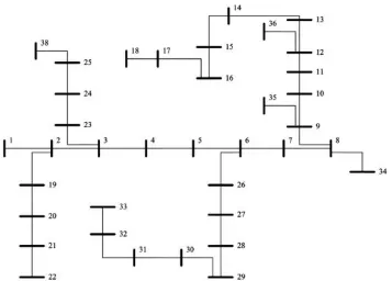
Fig-II IEEE 38-bus test system
Table – III
Results of IEEE 38-bus test system without and with multi DG For Constant Load model
Optimal location of DG-1 14 Optimal size of DG-1 0.629692 Total Ploss without DG (p.u) 0.202185
Total Ploss with DG-1 (p.u) 0.142857
Total Qloss without DG (p.u) 0.134828
Total Qloss with DG-1 (p.u) 0.094555
Optimal location of DG-2 (p.u) 31 Optimal size of DG-2 0.629692 Total Ploss with DG-2 (p.u) 0.113029
[image:7.612.190.424.401.582.2]Total Qloss with DG-2 (p.u) 0.074872
Table – IV
Comparison of Voltage Profiles for IEEE 38-bus test system without and with multi DG.
Bus Voltage (p.u) Voltage (p.u) Voltage (p.u) Without DG with DG-1 with DG-2
1 1 1 1
[image:7.612.172.440.625.732.2]Fig – III Comparison of Voltage Profiles for IEEE 38-bus test system without and with DG-1 and DG-2.
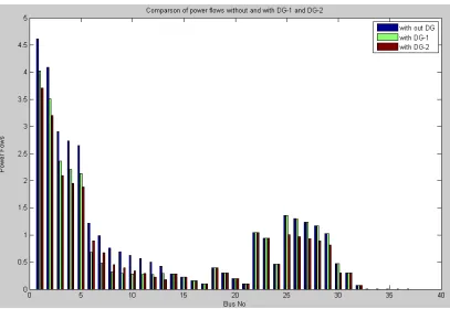
Table-III summarizes the optimal DG’s size- location pairs for IEEE 38-bus test system with constant load model and reduction in active and reactive power loss with DG’s are observed. Table-IV summarizes the voltage profile improvement of after placing the DG-1 and DG-2 at optimal locations. Fig-III gives Comparison of Voltage Profiles for IEEE 38-bus test system without and with DG-1 and DG-2. Fig-IV gives Comparison of Power flows for IEEE 38-bus test system without and with DG-1 and DG-2.
V. CONCLUSION
The classical Load Flow methods like Gauss-Siedel (GS), Newton-Raphson (NR) and Fast Decoupled are cannot be applied for Distribution Systems. Special methods like Distribution Load Flow (DLF) to be extremely useful for the study of radial Distribution Systems
The proposed current injection method can effectively work on redial as well as meshed Distribution Systems. Here we use Ybus instead of Zbus which is formed by sparsity technique. So implementation of control devices is very easy. The number of iterations The exhaustive analysis for size-location planning of distributed generation in multi objective optimization in Distribution Systems is presented. The multi objective criteria based on system performance indices of ILP and ILQ, related to real and reactive power losses, and IC and IVD, related to system MVA capacity enhancement and voltage profile improvement is utilized in the present work. It is observed that there is a significant difference exists in both size and location of DG.
REFERENCES
[1] Deependra Singh, Devender Singh, and K. S. Verma “Multi objective Optimization for DG Planning With Load Models” IEEE TRANSACTIONS ON POWER SYSTEMS, VOL. 24, NO. 1, FEBRUARY 2009.
[2] Jen-Hao Teng, Member, IEEE “A Direct Approach for Distribution System Load Flow Solutions” IEEE TRANSACTIONS ON POWER DELIVERY, VOL. 18, NO. 3, JULY 2003.
[3] K. Prakash, Member, IEEE, and M. Sydulu, Member, IEEE “An Effective Topological and Primitive Impedance based Distribution Load Flow Method for Radial Distribution Systems,” IEEE TENCON’2008.
[4] Paulo A. N. Garcia, Student Member, IEEE, Jose Luiz R. Pereira, Member, IEEE Sandoval Carneiro, Jr., Senior Member, IEEE, Vander M. da Costa, Member, IEEE, and Nelson Martins, Fellow, IEEE “Three-Phase Power Flow Calculations Using the Current Injection Method” IEEE TRANSACTIONS ON POWER SYSTEMS, VOL. 15, NO. 2, MAY 2000.
[5] S. Santoso, N. Saraf and G.K. Venayagamoorthy, "Intelligent techniques for planning distributed generation systems", IEEE Power Engineering Society General Meeting, 24-28 June 2007, pp. 1-4