ÚVOD
Jedným z najdôležitejších faktorov kvality každej stavby v dopravnom staviteľstve je nepochybne geometrická presnosť stavebných objektov. V záujme splnenia tejto požiadavky sú veľmi dôležitými účastníkmi v procese výstavby inžinierski geo-deti (v podzemí banskí merači), ktorí ako vysoko špecializovaný tím musia byť prítomní na každej stavbe. Článok je zameraný na plnenie ich úloh pri výstavbe podzemných líniových diel – tune-lov, štôlní, šácht, s rôznymi špecifikami týchto prác tak z pohľadu použitej metódy výstavby, ako aj z pohľadu rozdiel-nych nárokov niektorých krajín, kde sa podzemné stavebné práce realizovali. Opisované geodetické práce sa vykonávali na tuneloch razených buď Novou rakúskou tunelovacou metódou (NRTM), alebo tzv. Nórskou tunelovacou metódou (NTM).
Rozšírenie spomenutých metód je lokálne ohraničené. NTM je používaná prakticky výhradne len v škandinávskych krajinách (Nórsko, Švédsko, Fínsko), kde horninové prostredie je tvorené spravidla kompaktnými a veľmi súdržnými granitmi. Na ostat-nom území Európy je spravidla používaná NRTM.
Neoddeliteľnou súčasťou nielen pri opisovaných, ale aj pri všetkých ostatných metódach razenia tunelov sú geodetické (meračské) práce, ktoré si vyžadujú aplikáciu najmodernejších meračských metód a technológií. Článok sa zameriava iba na dve vybrané metódy (NRTM a NTM), pretože všetky tunelové stavby, na ktorých sa vykonávali opisované geodetické práce, boli realizované iba týmito dvomi metódami.
GEODETICKÉ MERANIA NA TUNELOCH RAZENÝCH NRTM NTRM je metóda, ktorá využíva výsledky z denných meraní 3D posunov tunelového ostenia (meranie konvergencie) potreb-né pre priebežnú optimalizáciu vystrojovacích prvkov tunela počas razenia a je teda úzko previazaná s meračskými prácami v tuneli.
Geodetické merania pri NRTM môžeme rozdeliť nasledovne: – budovanie bodov základnej vytyčovacej siete (ZVS)
a podrobnej vytyčovacej siete (PVS) a určenie ich polohy a výšky presným polygónovým a výškovým meraním, – vytyčovanie a usmerňovanie razenia,
– zameranie skutočného vyhotovenia denného postupu razenia a kontrola presnosti denného postupu vyrazeného tunela, – meranie 3D posunov v tuneli,
– geodetické práce pri reprofilácii tunela,
– geodetické práce pri zhotovovaní sekundárneho ostenia tunela a vozovky (prípadne železničného zvršku pri želez-ničných tuneloch).
Vytyčovacie práce a usmerňovanie razenia pri NRTM Na vytyčovanie a usmerňovanie razenia sa využívajú laserové systémy. Tieto sú spravidla tvorené buď štandardnými trubicový-mi líniovýtrubicový-mi lasertrubicový-mi, alebo „Automatickýtrubicový-mi vytyčovacítrubicový-mi lase-rovými systémami“ (AVLS). Použitie líniových laserov je stále
INTRODUCTION
One of the most important factors of quality of any traffic engi-neering structure is undoubtedly geometrical accuracy of structu-res. It is therefore in the interest of meeting this requirement that engineering surveyors (mine surveyors in the underground) are very important participants of the construction process. As a highly specialised team they must be present on each construc-tion site. This paper is focused on fulfilling their tasks in the con-struction of underground linear structures – tunnels, adits, shafts – with various specifics of these works in terms of both the con-struction method used and different requirements existing in some countries in which the underground structures were carried out. The survey described in the paper was performed for tunne-ls driven using the New Austrian Tunnelling Method (NATM) and the so-called Norwegian Tunnelling Method (NTM).
The spread of the above-mentioned methods is locally boun-ded. The NTM is used virtually exclusively in Scandinavian countries (Norway, Sweden, Finland), where the ground envi-ronment is formed by usually compact and highly coherent gra-nites. The NATM is usually applied within the other areas of Europe.
Surveying, requiring the application of the state-of-the-art sur-vey methods and equipment, is an inseparable part not only of the methods described in this paper but also of all other tunnel-ling methods. The paper is focused only on two selected methods (the NATM and the NTM) because of the fact that all tunnelling projects where our survey activities were carried out were reali-sed using these two methods.
SURVEYING FOR TUNNELS DRIVEN BY THE NATM The NATM is a method using results of measurements of dis-placements of a tunnel lining (convergence measurements) con-ducted every day to allow the continual optimisation of the exca-vation support elements during the course of the excaexca-vation. It is therefore closely connected with surveying in tunnels.
Surveying for the NATM can be divided as follows:
– establishing points of the basic setting out net (BSN) and detailed setting out net (DSN) and determining their positi-on and altitude by traversing and vertical survey.
– setting out and guiding the drive,
– taking the bearings of the actual day’s advance and checking on accuracy of the excavation completed during the day, – 3D measurement of displacements inside the tunnel, – surveying for re-profiling of the tunnel,
– surveying during the construction of the secondary tunnel lining and the roadway (or the track in railway tunnels).
Setting out and guidance during the NATM excavation
Laser systems are used for setting out and guidance. The sys-tems are usually based on standard tubular linear lasers or
GEODETICKÉ PRÁCE PRI REALIZÁCII TUNELOVÝCH A OSTATNÝCH
PODZEMNÝCH STAVIEB V DOPRAVNOM STAVITEĽSTVE
SURVEYING FOR TUNNELING CONSTRUCTIONS AND
OTHER UNDERGROUND CONSTRUCTIONS IN TRANSPORT
ENGINEERING INDUSTRY
PETER FERANČÍKAutomatic Setting out Laser Systems (ASLS). The use of linear lasers has still been quite much spread, both in our country and abroad (Slovenia, Croatia, Italy, Austria).
A linear laser is practically used only for visualising a spatial reference line from which orthogonal setting out elements (cha-inage and the perpendicular line) are subsequently calculated, usually in relation to an exactly specified point on a supporting frame (ARCUS, BRETEX, TH,...).
The majority of standard double-lane road tunnels are divided during the excavation into three vertical parts – top heading, bench and invert). The usual layout and number of linear lasers is: three lasers in top heading and two in the bench.
The calculation of setting out elements is carried out using methods (combining drawing software, e.g. AutoCad, with a suitable calculation program, e.g. GEUS, EXEL, REFLINE) or modern software developed directly for surveying on tunnel con-struction sites.
Angermeier’s Powervermessung, Geo 2000, ARCTech. and AMBERG’s Tunnel Measurement System (TMS) software is used in the department of survey of Tunely SK plant of Skanska SK. Both software groups have still been used on construction sites where survey measurements are carried out by our survey-ors. However, AMBERG’s TMS package has been recently used more because it is a complete software package for surveying in tunnels. The software contains more separate programs - TMS Office, TMS ProScan Plus, TMS SetOut, TMS Tunnelscan. The work using this program package is very effective.
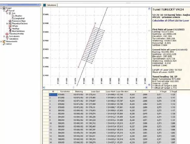
All design parameters of the tunnel (tunnel centre line, longi-tudinal section, cross-section, transverse incline, changes in cross-section) are put in the TMS Office program. Bearings of laser beams of linear lasers in the tunnel space are taken subse-quently (usually on two points). They are then put in the pro-gram. The program subsequently calculates all setting out ele-ments required for the correct incorporation of the frame into the tunnel primary li -ning. The form of the setting out pro-tocol (the program output) is obvious from Fig. 1.
The other, much more modern and sophisticated soluti-on for guiding the excavation is the use of the ASLS. In sub-stance, it is a com -bination of a survey instrument – a total station (electrical-op ti cal theodolite with a distance meter) and a linear laser. Significant progress has been experienced of late even in this field. Practically the majority of world’s manufacturers pro-duce total stations with a setting out laser installed direct-ly in the instrument, on the optical axis of the telescope. The dosť rozšírené, a to tak u nás, ako aj v zahraničí (Slovinsko,
Chorvátsko, ČR, Taliansko, Rakúsko).
Líniový laser slúži vlastne len na zviditeľnenie priestorovej referenčnej priamky, od ktorej sú následne počítané ortogonálne vytyčovacie prvky (staničenie a kolmica) spravidla k pres -ne určenému miestu na podpernom oblúku (nosník ARCUS, BRETEX, TH,...).
Väčšina štandardných dvojpruhových cestných tunelov je čle-nená počas razenia do troch vertikálnych častí – kaloty, stupňa a protiklenby. Obvyklé rozmiestnenie a počet líniových laserov je, že tri lasery sú v kalote a dva na stupni.
Na výpočet vytyčovacích prvkov sú využívané buď graficko-početné metódy (spojenie kresliaceho programu napr. AutoCAD a vhodného výpočtového programu napr. GEUS, EXEL, REFLI-NE), alebo moderné softvéry vyvinuté priamo pre geodetické práce na tunelových stavbách.
V geodetickej skupine Závodu Tunely SK spoločnosti Skanska SK a. s., sa využívajú softvéry od firiem Angermeier (Power -vermessung, Geo 2000, ARCTech.) a od firmy AMBERG (TMS – Tunnel Measurement System). Obidve skupiny softvérov sú stále používané na stavbách, kde vykonávajú geodetické merania naši geodeti, avšak v poslednom čase je viac využívaný balík TMS od firmy AMBERG, pretože ide o kompletný softvérový balík pre geodetické práce v tuneli. Softvér obsahuje viacero samostatných programov – TMS Office, TMS ProScan Plus, TMS SetOut, TMS Tunnelscan. Práca v tomto programovom balíku je veľmi efektívna.
V programe TMS Office sú zadefinované všetky projektované parametre tunela – os tunela, pozdĺžny rez, priečny rez, priečny náklon, zmena priečneho profilu. Následne sú zamerané lasero-vé lúče líniových laserov v priestore tunela (spravidla dvomi bodmi). Tieto sú potom zadefinované do programu a program následne vypočíta všetky potrebné vytyčovacie prvky pre správ-ne postavenie priehradového oblúka primárspráv-neho ostenia tuspráv-nela.
Obr. 1 Protokol o výpočte vytyčovacích prvkov v programe TMS Office. Autor – Ferančík
department of survey of Skanska SK uses exclusively instru-ments produced by Leica, which are at the worldwide cutting edge of the field of comprehensive survey solutions for measu-rements in tunnels, together with AMBERG’s TMS.
The ASLS, which is often called “the motorlaser”, usually comprises a total station and a remotely controlled process con-trol computer (Angermeier’s solution) (see Fig. 2) or only a remotely controlled total station (see Fig. 3) equipped with spe-cial software (TMS Set out). The work and preparation of setting out parameters were carried out as follows:
The same as in the previous case of using linear lasers, design geometrical parameters are put in the guidance program of the total station and, as well as measurement check points in the tunnel (usually convergence measurement points). Sub -sequently an ASLS total station (the motorlaser) is installed on a bracket in the tunnel and data on its location (coordinates X, Y, Z) and orientation are put in. The ASLS complex prepared in this way is prepared for setting out. Setting out is usually carri-ed out by shift technicians. For setting out the current position of a frame it is only necessary to select the respective part of the tunnel tube (the top heading or part of top heading, the bench) and filling of the current chainage of the frame. After this data has been put in the program, the instrument sets out pre-defined points around the arch circumference. The procedure is obvious from Fig. 4.
In the Slovak tunnels where surveying was carried out by our surveyors, we used both Angermeier’s system (the Branisko tun-nel and Sitina tuntun-nel) and AMBERG’s system (the Bôrik tuntun-nel).
The use of the ASVS for the excavation guidance is certainly a very modern and effective method. The disadvantage of this method lies in significantly higher acquisition costs compared to linear lasers and, in the case of a defect or damage to the instru-ment, the loss of the entire setting out system for the tunnel, taking into consideration the fact that this setting out complex usually serves more parts of the tunnel tube. On the one hand, changing or replacing the ASLS is simple; on the other hand, it requires a stand-by instrument, which is necessary to be present on site. This cost item cannot be neglected. In addition, the work with the ASLS requires well trained operators, first of all skilled in using the TMS Set out system. In any case, the use of the ASLS setting out complexes is a proper way to the future. Over time it will completely replace the use of classical linear lasers. In more developed European countries (Switzerland, Austria, Germany) it is practised already today.
Taking the bearings of the actual day’s advance and checking on accuracy at the NATM
Even despite the use of the state-of-the-art excavation guiding systems it is impossible when erecting a frame and other opera-tions on the arch to exclude a certain inaccuracy caused either by Forma vytyčovacieho protokolu (výstupu z programu) je zrejmá
z obr. 1.
Druhým podstatne modernejším a sofistikovanejším riešením na usmerňovanie razenia je využitie AVLS. Ide vlastne o spojenie geodetického prístroja – totálnej stanice (elektroop-tický teodolit s diaľkomerom) a líniového lasera. V poslednom čase došlo aj v tejto oblasti k výraznému pokroku. Prakticky väč-šina svetových výrobcov už vyrába totálne stanice s vyty -čovacím laserom umiestneným priamo v prístroji v optickej osi ďalekohľadu. V geodetickej skupine firmy Skanska SK sa využí-vajú výhradne len prístroje firmy Leica, ktoré sú vo vývoji tých-to vytyčovacích systémov vyvíjaných spoločne s firmou AMBERG (TMS) na špičke svetových ucelených geodetických riešení pre meranie v tuneloch.
AVLS, často nazývaný tiež „motorlaser“, pozostáva spravidla z totálnej stanice a riadiaceho počítača s diaľkovým ovládaním (riešenie firmy Angermeier) – obr. 2, alebo len z totálnej stanice s diaľkovým ovládaním (tzv. remote control – obr. 3) vybavenej špeciálnym softvérom (TMS Set out). Práca a príprava vytyčo-vacích parametrov prebieha nasledovne.
Obr. 2 Zostava kompletu AVLS (Motorlasera) – riešenie firmy Angermeier – SRN. Autor – Ferančík
Fig. 2 The set of the AVLS (Motorlaser) package – Angermeier (FRG) solution. Author – Ferančík
Obr. 4 Ukážka vytyčovania bodov Motorlaserom pre postavenie priehradové-ho nosníka. Autor – Manuál k programu TMS-Leica
Fig. 4 Presentation of setting out points applying a Motorlaser to the instal-lation of a frame. Author – Program manual for TMS-Leica
Obr. 3 Ďiaľkové ovládanie AVLS (Motorlasera) – riešenie firmy Amberg--Leica – Švajčiarsko. Autor – Manuál k programu TMSAmberg--Leica
Fig. 3 AVLS (Motorlasera) remote control – Amberg-Leica (Switzerland) solution. Author – Program manual for TMS-Leica
the human factor or the geometrical inaccuracy of the arch used (ARCUS, BRETEX, TH).
For that reason independent daily checking usually on each arch and shotcrete primary lining of the tunnel is required. The checks are carried out, it is possible to say, solely using the polar method. The position and orientation of the instrument is deter-mined using the application software for the Free Station instru-ment. Instruments manufactured by Leica are also used. They are equipped with the above-mentioned TMS software, concretely the TMS ProScan plus application program. The great advantage of this solution is that the entire database and structure of the design, which was put in and calculated during the work on set-ting out and guiding the excavation (as described in the previous chapter), and the possibility of immediate evaluation of the mea-sured data or visualisation and comparison of the meamea-sured data with the design directly in the tunnel, is available on the instru-ment display. If the surveyor is present during the erection of the arch in the tunnel, he or she can simultaneously check on the installation of the actual arch at the tunnel face and perform check survey of cross-sections of the profiles of the primary lining com-pleted during previous shifts. They instantaneously give notice to operating technicians about contingent inaccuracies.
Another great advantage of this software solution (TMS ProScan plus) is the possibility of the automatic measurement of the tunnel cross-sections. This advantage is made use of first of all in the cases of higher daily advance rates and later when the tunnel is being re-profiled. All measured profiles are subsequ-ently assessed using TMS Office program. They are printed and hard copies are handed over to all parties involved (operation, site supervision, designer). The assessment is presented in Fig. 5.
3D measurement of displacements inside the tunnel for the NATM
For the NATM, 3D measurements of displacements of the pri-mary tunnel lining (in the praxis also called convergence measu-rements) are extremely important. They allow the confirmation of the adequacy of the tunnel lining thickness proposed to be optimised or its thickness to be increased (but also reduced). The most precise instruments are used for the 3D measurements. There are instruments Leica TC 1800 and Leica TCRM 1201 used in our department of survey. These high precision instru-ments feature angle accuracy of 1” (0.3 mgon) and the distance meter accuracy of 1mm +/- 1,5 ppm. If certain geometrical prin-ciples are used and a suitable method and configuration of the points to be surveyed are chosen, it is possible to achieve the measurement accuracy of +/- 1 to 2 mm. In a certain way this is relative accuracy. This accuracy is defined by the standard devi-ation calculated from two or more independent measurements on the same point (or more points) on the convergence profile sur-veyed within a short interval of time (so that contingent move-ment of the point is excluded) at the measuremove-ment accuracy inverse analysis of using generally applicable formulas for the calculation of standard deviations.
The effort is apparent in recent years to absolutise this accura-cy by means of the so-called supervision over the geotechnical monitoring, the part of which are 3D measurements of displace-ments in the tunnel. As a matter of fact this is continual impro-ving of measurements using substantially more demanding met-hods (traversing, network measurement with great number of redundant measurements) with the aim of approaching the real 3D position of the surveyed point as close as possible. The rea-son of this effort is the use of the points on convergence profiles for guiding the excavation even during the subsequent phases of the tunnel construction as the detailed setting out net (DSN) in the tunnel. The DSN points in the tunnel are usually surveyed from the basic setting out net points installed for the tunnel on Do riadiaceho programu totálnej stanice sú rovnako ako
v predchádzajúcom prípade pri použití líniových laserov zadefi-nované geometrické parametre projektu a naviac kontrolné merač-ské body v tuneli (spravidla body na meranie konvergencie). Následne je totálna stanica AVLS (motorlaser) osadená na konzo-lu do tunela a sú zadefinované údaje o jej polohe (súradnicami X, Y, Z) a orientácii. Takto nastavený komplet AVLS je pripravený k vytyčovaniu. Vytyčovanie je realizované spravidla zmenovými technikmi. Na vytýčenie aktuálnej polohy priehradového oblúka je už len vybraná požadovaná časť tunelovej rúry (kalota, poprípa-de časť kaloty, stupeň) a je zadané aktuálne staničenie priehrado-vého oblúka. Po zadaní týchto údajov prístroj vytyčuje vopred zadefinované body po obvode oblúka. Postup je zrejmý z obr. 4.
Na slovenských tuneloch, kde boli geodetické práce vykoná-vané našimi geodetmi, boli využívykoná-vané tak komplety od firmy Angermeier (tunel Branisko, tunel Sitina) ako aj komplety od firmy AMBERG (tunel Bôrik).
Využitie AVLS pri usmerňovaní razenia je rozhodne veľmi modernou a efektívnou metódou. Jej nevýhodou sú podstatne vyššie obstarávacie náklady oproti líniovým laserom a v prípade poruchy, alebo poškodenia prístroja, strata celého vytyčovacieho systému pre tunel, pretože spravidla tento vytyčovací komplet obsluhuje viacero častí tunelovej rúry. Výmena alebo nahradenie AVLS je síce jednoduchá a rýchla, vyžaduje si však náhradný prístroj, čo je nezanedbateľná cenová položka, pretože je potreb-né mať na stavbe rezervný komplet. Práca s AVLS si tak isto vyžaduje dobre zaškolenú obsluhu predovšetkým pri používaní riešenia TMS Set out. V každom prípade je však použitie vyty-čovacích kompletov AVLS určite cestou do budúcnosti, ktorá časom celkom nahradí používanie klasických líniových laserov. Vo vyspelejších a rozvinutejších krajinách Európy (Švajčiarsko, Rakúsko, Nemecko) sa to už v súčasnosti praktizuje.
Zameranie denného postupu razenia a kontrola presnosti pri NRTM
Aj napriek použitiu najmodernejších systémov na usmerňova-nie razenia usmerňova-nie je možné pri ustavovaní priehradového oblúka ako aj ďalších operáciách s oblúkom vylúčiť určitú nepresnosť zapríčinenú buď ľudským faktorom, alebo samotnou geometric-kou presnosťou používaného oblúka (ARCUS, BRETEX, TH). Z tohto dôvodu je potrebná nezávislá denná kontrola spravidla každého oblúka, ako aj striekaného betónu primárneho ostenia tunela. Na kontrolu sa využíva výhradne meranie polárnou metó-dou. Na určenie polohy a orientácie prístroja sa využíva aplikačný program prístroja – Voľné stanovisko. Používajú sa tak isto prí-stroje firmy Leica, vybavené spomenutým softvérom TMS, kon-krétne aplikačným programom TMS ProScan plus. Veľkou výho-dou tohto riešenia je tak využívanie celej databázy a štruktúry pro-jektu, ktorá je už zadefinovaná a vypočítaná pri vytyčovaní a usmerňovaní (opísaná v predošlej kapitole), ako aj možnosť oka-mžitého vyhodnotenia nameraných údajov, resp. zobrazenia a porovnania nameraných údajov s projektom priamo v tuneli na displeji prístroja. V prípade, ak je geodet prítomný pri ustavovaní oblúka v tuneli, tak môže súčasne kontrolovať osadenie aktuálne-ho oblúka na čele tunela a kontrolne zamerať priečne profily už hotových profilov primárneho ostenia zhotovených v priebehu predchádzajúcich pracovných zmien. Okamžite tiež upozorňuje prevádzkových technikov na prípadné nepresnosti.
Ďalšou veľkou výhodou tohto softvérového riešenia (TMS ProScan plus) je možnosť automatického merania priečnych pro-filov tunela, čo sa využíva hlavne pri väčších denných postupoch razenia, ako aj pri neskoršej reprofilácii tunela. Všetky namera-né profily sú následne vyhodnotenamera-né ešte v programe TMS Office a vytlačené a expedované v papierovej forme zainteresovaným účastníkom stavby (prevádzka, stavebný dozor, projektant). Vyhodnotenie je zrejmé z obr. 5.
Meranie 3D posunov tunelového ostenia pri NRTM
Pri NRTM má meranie 3D posunov primárneho ostenia tunela (v praxi je tiež používaný výraz meranie konvergencie) veľký význam z dôvodu optimalizácie potvrdenia dostatočnosti navrh-nutej hrúbky ostenia tunela, poprípade jej zosilnenia (alebo aj zoslabenia). Na meranie 3D deformácií sa využívajú najpresnej-šie prístroje. V našej geodetickej skupine sú to prístroje Leica TC 1800 a Leica TCRM 1201. Ide o veľmi presné prístroje s uhlovou presnosťou 1” (0,3 mgon) a presnosťou diaľkomera 1mm +/–1,5 ppm. Pri použití určitých geometrických zásad, vhodnej voľbe metódy a konfigurácií meraných bodov konvergenčných profi-lov je možné dosiahnuť presnosť merania +/–1 až 2 mm. Určitým spôsobom ide o relatívnu presnosť. Táto presnosť je definovaná smerodajnou odchýlkou vypočítanou z dvoch, alebo viacerých nezávislých meraní toho istého bodu (alebo viacerých bodov) konvergenčného profilu, zameraného v krátkom časovom rozpätí (z dôvodu vylúčenia prípadného pohybu bodu), pri aposterior-nom rozbore presnosti merania s použitím všeobecne platných vzorcov pre výpočet smerodajných odchýliek.
V posledných rokoch je viditeľná snaha o absolutizáciu tejto presnosti tzv. supervíziou geotechnického monitoringu, ktorého súčasťou sú merania 3D posunov v tuneli. Ide vlastne o neustále spresňovanie merania s použitím podstatne náročnejších metód (polygónové meranie, sieťové meranie s veľkým počtom nadby-točných meraní), z dôvodu čo najväčšieho priblíženia sa skutoč-nej 3D polohe meraného bodu. Dôvodom tejto snahy je využíva-nie bodov konvergenčných profilov na usmerňovavyužíva-nie razenia aj v neskorších fázach výstavby tunela ako bodov podrobnej vyty-čovacej siete (PVS) tunela. Body PVS tunela sú spravidla zame-riavané z bodov základnej vytyčovacej siete (ZVS) tunela na povrchu a v tuneli. Pri výpočtoch čo najpresnejšej polohy bodov ZVS a PVS sú využívané špeciálne programy na vyhodnotenie sieťových meraní (PLS, Groma, Leica Geo Office – LGO).
V ďalších fázach výstavby tunela sú tieto body brané ako pod-klad pre nové body PVS tunela umiestnené v sekundárnom oste-ní tunela. Tieto nové body PVS sú potom využívané až do ukon-čenia všetkých geodetických prác v tuneli, prípadne je ešte časť z nich využitá na meranie konvergencie sekundárneho ostenia tunela.
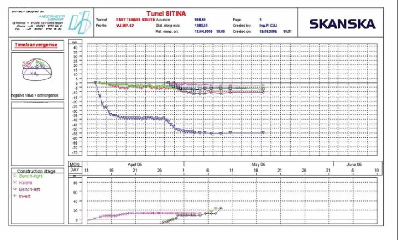
Denné merania 3D posunov primárneho ostenia tunela sú spra-cované v príslušných softvéroch a expedované denne vybraným účastníkom stavby buď v papierovej forme vo forme grafov, alebo najnovšie publikované vo forme grafov a tabuliek na webových stránkach na to zriadených. Merania 3D posunov bývajú spravidla zapracované ako súčasť geotechnického moni-toringu (GTM) tunela a v súčinnosti s ostatnými meraniami GTM tvoria dôležitú súčasť NRTM. Grafické vyhodnotenie meraní je na obr. 6 a 7.
V posledných rokoch sme vykonávali konvergenčné merania na tuneloch Bôrik (SR) a Tuneloch Tábor, Barnica a Markovec v Slovinsku, kde boli tieto merania spracovávane v softvéri ARCTECH od firmy Angermeier. V súčasnosti vykonávajú naši geodeti merania 3D posunov na stavbe železničného tunela Turecký vrch. Namerané údaje sú vyhodnocované v programe BARAB od firmy ARCADIS – Geotechnika, a. s., a publikované na web stránkach firmy ARCADIS, ktorej dcérska spoločnosť Geofos, s. r. o., je aj dodávateľom celého geotechnického moni-toringu na stavbe tunela Turecký vrch. Na obr. 8 je geodet pri kontrole presnosti prerážky ľavej tunelovej rúry Tunela Barnica v Slovinsku.
Geodetické práce pri reprofilácii tunela razeného NRTM Na meranie pri reprofilácii tunela sa používajú prístroje Leica s možnosťou bezodrazového merania dĺžok (TCRM 1201) a softvér TMS ProScan plus. Opis merania už bol spomenutý v predchádzajúcich kapitolách. V tejto fáze meraní sa využíva už
the surface and in the tunnel. Special programs for assessing the network survey (PLS, Groma, Leica Geo Office – LGO) are used in calculations of the as accurate position of BSN and DSN points as possible.
In the subsequent tunnel construction phases these points are used as grounds for new DSN points installed in the secondary tunnel lining. These new DSN points are subsequently used till the conclusion of all surveying in the tunnel or a part of the points remain to be used for convergence measurements on the secondary tunnel lining.
Daily 3D measurements of the primary lining displacements are processed in respective software and sent every day to selected par-ties to the construction either in the form of hard copies or as graphs or, in the newest way, they are published in the form of charts and tables on web pages created for this purpose. 3D measurements of displacements are usually processed as a part of geotechnical moni-toring (GTM) of the tunnel; together with other GTM measure-ments they form a significant part of the NATM. Graphical evalua-tion of measurements is presented in Figures 6 and 7.
During recent years we have carried out convergence measu-rements on the Bôrik tunnel (the SR) and the Tábor, Barnica and Markovec tunnels in Slovenia, where these measurements were processed using Angermeier’s software ARCTECH. Today our surveyors are carrying out 3D measurements of displace-ments on the Turecký Vrch railway tunnel construction. The measured data is evaluated using the BARAB program develo-ped by ARCADIS, a branch of which, Geofos s.r.o., is, in addi-tion, a contractor for geotechnical monitoring services on the Turecký Vrch tunnel construction. Figure 8 shows a surveyor checking on the accuracy of the left tunnel tube of the Barnica tunnel breakthrough, Slovenia.
Surveying for re-profiling of a tunnel driven by the NATM
Surveying during the work on re-profiling a tunnel is perfor-med using Leica instruments with the facility for reflectionless distance measurement (TCRM 1201) and TMS ProScan plus software. The measurement was described in previous chapters. In this measurement phase only automatic measurement of paral-lel vertical profiles is carried out; the grid selected for measuring points on the primary tunnel lining is substantially denser (usu-ally 1x1 m). The measurements are usu(usu-ally performed twice. For the first time it is before the repair and application of the final layer of shotcrete, while the second measurement is carried out after the completion of the primary lining treatment, before installing the intermediate waterproofing system.
The outputs have a graphical-numerical form (cross-sections), demonstrating deviations of the actual tunnel cross-section from the design profile. These outputs are handed over in hard copies to the project owner and become part of the as-built design docu-ments for the primary tunnel lining. The format for the assess-ment is similar to the format for daily checks on the excavation (see Fig. 5).
The use of laser scanners is another very efficient and modern alternative for these measurements. There are several manufac-turers today offering comprehensive hardware – software soluti-ons (Leica+AMBERG, RIEGEL+ Geodata). These are very effi-cient solutions, allowing the measurements to be carried out along about 50 m of a tunnel during approximately half an hour, to an accuracy of up to one centimetre, providing great numbers of measured points making the development of a faithful 3D model of the tunnel tube possible. On the other hand, this soluti-on is quite expensive, with the purchase costs of EUR 80 – 150 thousand. It is therefore applicable exclusively to a certain part of measurements in a tunnel. In any case, this is a trend which has been becoming a standard virtually on all tunnel constructi-on sites abroad. As far as surveying of a secconstructi-ondary lining is
len výsledok automatického merania paralelných vertikálnych profilov, pričom je zvolený podstatne hustejší raster zameraných bodov na primárnom ostení tunela (zvyčajne 1x1m). Merania sa vykonávajú spravidla 2 krát. Prvýkrát pred samotnou opravou a nástrekom finálnej vrstvy striekaného betónu a druhýkrát až po finalizácii úpravy primárneho ostenia, pred pokladaním medzi-ľahlej hydroizolácie.
Z merania sú vyhotovené graficko-čiselné výstupy (priečne profily) so znázornením odchýlok skutočného priečneho profilu tunela od projektovaného profilu. Tieto sú expedované v papierovej forme investorovi a tvoria súčasť dokumentácie skutočného vyhotovenia stavby (DSVS) primárneho ostenia tunela. Vzor vyhodnotenia je obdobný ako pri dennej kontrole razenia (obr. 5).
Veľmi výkonnou a modernou alternatívou na tieto merania je aj využitie laserových skenerov. V súčasnosti ponúka viacero výrob-cov ucelené hardvérovo-softvérové riešenia (Leica+AMBERG, RIEGEL+ Geodata). Ide o veľmi výkonné riešenia, ktoré umožňujú v priebehu cca 0,5 hodiny zamerať cca 50 m tunela s pres -nosťou do jedného centimetra a veľkým počtom nameraných bodov, z ktorých je možno vytvoriť verný 3D model tunelovej rúry. Toto riešenie je však dosť drahé, nadobúdacie náklady 80–150 tisíc eur a je úzko využiteľné len na určitú časť meraní v tuneli. V každom prípade je to však trend, ktorý sa pomaly stáva štandardom prakticky na všetkých stavbách tunelov v zahraničí. Pri zameriavaní sekundárneho ostenia dokonca už aj v tuneloch v ČR a SR.
Geodetické práce pri zhotovovaní sekundárneho ostenia tunela razeného NRTM
Geodetické (meračské) práce sa vykonávajú s použitím rovna-kého prístrojového a softvérového vybavenia ako pri predchád-zajúcich fázach tunela. V tejto fáze, keď je v tuneli budované veľké množstvo súvisiacich objektov (drenážne potrubie, zákla-dové pásy, výklenky, káblové kolektory), je veľmi výhodné pou-žitie aplikačného programu TMS ProScan plus v geodetickom
concerned, it is so even on tunnels in the CR and SR.
Surveying during the construction of the secondary lining of the NATM driven tunnel
Survey operations are car-ried out using the same instruments and software as those used during the prece-ding tunnelling phases. In this phase, during which many associated structures are constructed inside the tunnel (drainage lines, strip foundations, recesses, cable ducts) it is very beneficial if the TMS ProScan plus soft-ware is installed in the survey instrument. The location and shape of the majority of structures, because a tunnel is a linear structure, are very simply defined in the design by means of the tunnel chainage and usually identical profile coordinates within a tunnel cross-section. This property is used in creating setting out protocols, where surveyors consecutively, throughout the tunnel length, set out identical profile coordina-tes, which are shown on the display of the instrument and are continually checked by the surveyor during the survey in the tun-nel itself – of course for the respective structure. An identical procedure is applied to setting out characteristic points of the cross-section of the secondary tunnel lining. They are calculated from the design, then a traveller form for casting of the tunnel upper vault is calibrated according to them and then setting in the required (design) position and tunnel chainage by the surve-yor only remains to be done. On the Turecký Vrch tunnel con-struction, where surveying is being carried out by our surveyors, the upper vault is built from reinforced concrete throughout the tunnel length; this puts increased requirements even on survey-ing. Steel reinforcement of concrete, which is installed in the first phase, before the traveller form is moved in, has to be set in an accurate position. For that reason even a certain part of the reinforcement (the ARCUS lattice girder) is set out and checked by surveyors. In addition, the exact border between casting blocks is set out by surveyors because of the increase in the thickness of the intermediate waterproofing system and the installation of a rubber waterstop (from the geometrical point of view this is a junction between a plane led through the front end of the block of the secondary and primary linings) – the term of “fugenband”, which was borrowed from German, is often used in practice.
The same procedure is applied even when the roadway and walkway structures are being constructed. The only exception is the possibility to use an application program developed for roads, the Road Line in Leica total stations (named Road Runner in newer instruments).
SURVEYING FOR TUNNELS DRIVEN BY THE NTM
In Scandinavian countries, as opposed to other countries in Europe, tunnels are driven virtually only through hard compact rock mass, nearly exclusively comprising hard granites and gra-nitic gneiss. In such good geological conditions the necessity of primary lining in the form we know from the NATM is virtually excluded. The tunnel support usually consists only of a thin layer
Obr. 5 Vyhodnotenie kontrolného zamerania priečneho profilu v programe TMS Office. Autor – Ferančík
Fig. 5 Assessment of a check survey of a cross-section in TMS Office softwa-re. Author – Ferančík
of micro-fibre reinforced shotcrete. Tunnels are driven full-face, using the drill and blast technique.
With respect to the absence of the primary lining, great stress is placed on as accurate drilling in the excavation face as sible and on the so-called “smooth blasting” (as accurate as pos-sible and least undulated contour of the tunnel tube after blasting and scaling of the face). Drilling is carried out by ATLAS COPCO or TAMROCK drill rigs. A great stress is placed on as high degree of automation and accuracy of drilling operations as possible as early as the phase of the drilling rigs development. For that reason drilling rigs are equipped with well refined soft-ware, first of all the BEVER CONTROL system developed by BEVER CONTROL AS (Norway), which is designed for ATLAS COPCO drill rigs. This is a comprehensive software package for fully automated drilling in the excavation face. The office part of the software package - Tunel Manager Lite (TML), which is used for the input of design geometrical parameters, is similar to the above-mentioned AMBERG’s TMS Office softwa-re. All design geometrical data is subsequently exported and loa-ded through the PCMCIA card to the above-mentioned BEVER CONTROL program installed on the drilling rig. The last step before starting the drilling operation itself is only the so-called navigation of the drill rig, which is implemented in two steps. First the Laser Measurement Group (a reference laser line reali-sed by a beam of the linear laser) is put in the program using two points (specifying coordinates X, Y, Z). Subsequently one of the drill rig feeds is set on this straight line by means of two special targets and the actual chainage of the face is put in the program. After the position of the feed being navigated is initiated and recorded, the drill rig is capable of automatic independent dril-ling, maintaining very high accuracy of the tunnel contour.
The task of a surveyor in the case of the NTM tunnel con-struction method is defined by the following activities:
– preparing a design for the drill rig and the BEVER CONTROL system,
prístroji. Umiestnenie a tvar väčšiny objektov, keďže tunel je líniová stavba, sú veľmi jednoducho definované v projekte a to staničením v tuneli a spravidla rovnakými profilovými súradni-cami v priečnom profile tunela. Táto vlastnosť sa využíva pri vytvorení vytyčovacich protokolov, pričom geodeti následne vytyčujú počas celej dĺžky trasy tunela rovnaké profilové súrad-nice, ktoré sú zobrazované na displeji prístroja a priebežne kon-trolované geodetom pri samotnom meraní v tuneli – samozrejme pre príslušný objekt. Úplne rovnako sú vytyčované aj charakte-ristické body priečneho profilu sekundárneho ostenia tunela. Tieto sú vypočítané z projektu, následne je podľa nich skalibro-vaný debniaci voz na betonáž hornej klenby tunela a potom je tento už len geodetom ustavený do požadovanej (projektovanej) polohy a staničenia tunela. Na tuneli Turecký vrch, kde vykoná-vajú meračské práce naši geodeti, je horná klenba sekundárneho ostenia v celej dĺžke tunela budovaná zo železobetónu, čo kladie zvýšené nároky aj na geodetické práce. Oceľová výstuž betónu, ktorá je budovaná v prvom slede ešte pred presunom debniace-ho voza, musí byť osadená do presnej pozície. Z tohto dôvodu je aj určitá časť výstuže (priehradový nosník ARCUS) vytyčovaná a kontrolovaná geodetmi. Rovnako je geodetmi vytyčovaná aj presná hranica medzi blokmi, z dôvodu zosilnenia medziľahlej hydroizolácie a montáže gumového hydroizolačného pásu (geo-metricky ide o prienik roviny preloženej čelom bloku sekundár-neho ostenia a primársekundár-neho ostenia) – v praxi je často používaný termín prevzatý z nemčiny – tzv. „fugenband“.
Rovnako sa postupuje aj pri zhotovovaní konštrukcie vozovky a chodníkov. Výnimkou je len možnosť použitia aplikačného programu určeného pre cesty Road Line (Road Runner pri nov-ších prístrojoch) totálnej stanice Leica.
GEODETICKÉ PRÁCE PRI TUNELOCH BUDOVANÝCH NTM V škandinávskych krajinách sú na rozdiel od ostatných krajín Európy tunely budované prakticky len v tvrdých kompaktných horninách, skoro výhradne tvorených veľmi tvrdými granitmi
Obr. 6 Grafické vyhodnotenie merania 3D posunov (vertikálna zložka–sadanie) v programe ARCTech – Angermeier. Autor – Ferančík Fig. 6 Graphical evaluation of 3D displacements (vertical component – subsidence) in ARCTech – Angermeier program. Author – Ferančík
– updating drill patterns proposed,
– installing, taking the bearings and setting of the linear laser in the tunnel and updating it within the BEVER CONTROL system on the drilling rig,
– surveying the day advance of the excavation – usually only the excavation after trimming,
– installing and continual checking on the BSN and DSN in the tunnel,
– surveying the structure after the completion and preparing as-built design documents.
The newest models of ATLAS COPCO drill rigs are already equipped with a 3D profiler, checking the day’s excavation a granitickými rulami. Pri takýchto veľmi dobrých geologických
podmienkach prakticky odpadá primárne vystrojenie tunela v tej podobe, ako ho poznáme pri NRTM. Vystrojenie tunela pozo-stáva spravidla len z nástreku tenkej vrstvy (mikroarmovaného) striekaného betónu s rozptýlenou výstužou. Razí sa v plnom pro-file tunela s nedelenou čelbou a s použitím vrtno-trhacích prác. Z dôvodu absencie primárneho ostenia je kladený veľký dôraz na čo najpresnejšie navŕtanie čelby a tzv. „hladký vylom“ (čo najpresnejší a najmenej členitý obrys tunelovej rúry po odstrele a začistení čelby). Na vŕtanie sa využívajú vrtné vozy firiem ATLAS COPCO, alebo TAMROCK. Už pri vývoji vŕtacích vozov je kladený veľký dôraz na čo najväčšiu automatizáciu a presnosť vŕtacích prác. Z tohto dôvodu sú vrtné vozy vybavené veľmi prepracovaným softvérom, predovšetkým je to softvér BEVER CONTROL od firmy BEVER CONTROL AS (Nórsko) určený pre vrtné vozy firmy ATLAS COPCO. Ide o ucelený soft-vér na plne automatické vŕtanie čelby. Kancelárska časť softvé-rového balíka – Tunel Manager Lite (TML), ktorá slúži na zada-nie geometrických parametrov projektu, je podobná už spome-nutému softvéru TMS Office od firmy AMBERG. Všetky geo-metrické údaje projektu sú následne exportované a nahrané cez PCMCIA kartu do už spomenutého ovládacieho programu BEVER CONTRTOL vŕtacieho voza. Posledným krokom na spustenie samotného vŕtania je už len tzv. navigácia vrtného voza, realizovaná v dvoch krokoch. Najskôr je do programu zadaná tzv. laserová skupina – referenčná laserová priamka rea-lizovaná lúčom líniového lasera – dvoma bodmi (súradnicami X, Y, Z). Následne je za pomoci dvoch špeciálnych terčov nastave-ná do tejto priamky jedna z lafiet vrtného voza a je zadané aktu-álne staničenie čelby. Po inicializácií a zapísaní polohy navigo-vanej lafety je vŕtací voz schopný samostatne automaticky vŕtať, pri zachovaní veľmi dobrej presnosti obrysu tunela.
Úloha geodeta pri NTM metóde výstavby tunela je vlastne definovaná týmito činnosťami:
Obr. 7 Grafické vyhodnotenie merania 3D posunov (zložka–konvergencia) v programe ARCTech – Angermeier. Autor – Ferančík Fig. 7 Graphical evaluation of 3D displacements (component: convergence) in ARCTech – Angermeier program. Author – Ferančík
Obr. 8 Kontrola presnosti prerážky ľavej tunelovej rúry na Tuneli Barnica v Slovinsku. Autor – Ferančík
Fig. 8 Checking on accuracy of the breakthrough of the left tunnel tube of the Barnica tunnel, Slovenia. Author – Ferančík
advance (see Fig. 9). The measurement method and assessment are obvious from Fig. 10.
Attention is also paid to achieving as fast and accurate pos-sible navigation of the drill rig as pospos-sible. The newest models already use navigation by means of a profiler and two to three fix points located on the tunnel lining or by means of a survey total station and two points installed directly on the drill rig (see Fig. 11). The effort is obvious during the NTM tunnel excavation to achieve as high degree of automation as possib-le within the entire process of guiding the drilling directly by the drilling equipment. This is in substance a method which is the replacement of the guidance of excavation by surveyors and total stations in tunnels constructed by the NATM. Tunnels constructed by the NTM usually have no primary lining as we know it at the NATM. The excavation is suppor-ted only by a layer of fibre reinforced shotcrete in locations where the geology is slightly disturbed. Subsequently a final layer mostly 8 to 10 cm thick, substituting the secondary lining, is applied.
Surveying of a day’s excavation advance or the final sur-veying of the tunnel lining at the NTM is often carried out using Laser scanners manufactured either by Leica or other companies.
This method was applied to the construction of the lining in the Porvarinlahti and Labbacka tunnels, parts of the VUOLI project at the eastern edge of Helsinki and the Orosmaki and Karnainen tunnels on the E 18 motorway between Helsinki and Turku.
The work of a surveyor during the construction of a se -condary tunnel lining lies in surveying final tunnel cross-sec-tions (the equivalent of re-profiling at the NATM) and incorpo-rating them into the as-built design documents, which had the form of a 3D tunnel model in the case of the above-mentioned tunnels.
The last phase of the work in tunnels driven by the NTM is the construction of technical service structures (tunnel draina-ge, cable tunnels etc.) and the roadway. These items of work virtually do not differ from the work on tunnels built by the NATM. The same applies to surveying, where identical proce-dures, software and instruments are used.
CONCLUSION
Tunnel engineering has been experiencing great boom in the recent years, first of all because of the continual impro-vement of traffic infrastructure of European countries, but also because of environmental protection efforts to transfer the ever denser traffic from surface roads underground. An inseparable and very important part of the construction works is performed by surveyors. They significantly contribute to the success of tunnel construction projects. The introduction and selection of a suitable system of survey measurements into the general construction system is a contribution significant for both the acceleration of construction processes and the adherence to geometrical parameters of the structures, which is placed great importance on. Adhering to the final, usually very high, accuracy of these structures is first of all influenced by surveyors, not only during the course of the constructi-on but also after its completiconstructi-on, by periodical checking on geometrical – príprava projektu pre vŕtací voz a systém BEVER
CON-TROL,
– aktualizácia navrhnutých vrtných schém,
– osadenie, zameranie a nastavenie líniového lasera v tuneli a jeho aktualizácia v obslužnom softvéri BEVER CON-TROL vrtného voza,
– zameranie denného postupu razenia – spravidla len začiste-ný výlom,
– budovanie a priebežná kontrola ZVS a PVS tunela, – zameranie stavby po ukončení a vypracovanie DSVS. V najnovších modeloch sú už vrtné vozy firmy ATLAS COPCO vybavené 3D profilerom na kontrolu denného postupu razenia (obr. 9). Spôsob merania a vyhodnotenie je zrejmé z obr. 10.
Pozornosť je tiež venovaná dosiahnutiu čo najrýchlejšej a najpresnejšej navigácie vrtného voza. Najnovšie modely už používajú navigáciu pomocou profilera a dvoch až troch pev-ných bodov umiestnepev-ných na ostení tunela, alebo pomocou geodetickej totálnej stanice a dvoch bodov umiestnených pria-mo na vrtnom voze (obr. 11). Pri razení tunelov NTM je vidi-teľná snaha o čo najväčšiu automatizáciu celého procesu vŕtania priamo vrtnou technikou. Ide vlastne o spôsob, ktorý je náhra-dou usmerňovania razenia geodetmi pomocou lasera a totálnych staníc pri tuneloch budovaných NRTM. Tunely budované NTM spravidla nemajú primárne ostenie tak ako to poznáme pri NRTM. Výlom je spevnený len vrstvou striekaného betónu
Obr. 9 Ukážka umiestenia 3D profilera a navigácia vrtného voza líniovým laserom – systém Bever Control – Atlas Copco. Autor – Manuál k programu Bever Control
Fig. 9 Presentation of the location of a 3D profiler and navigation of a drill rig by means of a linear laser – the Atlas Copco Bever Control system. Author – Manual for the Bever Control program
Obr. 10 Schéma zamerania výlomu a vyhodnotenia Bever profilerom – Atlas Copco. Autor – Manuál k programu Bever Control
Fig. 10 A chart of the survey of the excavation and its assessment using the Atlas Copco Bever profiler. Author – Manual for the Bever Control program
parameters (3D displacements of the secondary lining, chec-king on rail track, ...). In addition, an important role is play-ed by manufacturers of survey and drilling equipment inclu-sive of respective software, striving for as high degree of automation of their products as possible. At last but not least, their role is in achieving of high productivity and accuracy of measurements and, of course, making the work of surveyors easier and simpler. It is necessary to realise that surveyors performing measurements inside a tunnel are virtually conti-nuously exposed to extreme conditions (poor visibility, high rate of airborn dust in the tunnel, constrained space conditi-ons) and, despite using sophisticated hardware and software solutions, the human factor remains to play the deciding role in the final result of their work. This is also one of the rea-sons why the work of a surveyor, operating always with mil-limetres, requires in these demanding conditions technically sound and resistant persons, deserving admiration and appre-ciation.
ING. PETER FERANČÍK, [email protected], Skanska SK a. s. – Závod Tunely SK s rozptýlenou výstužou v miestach s mierne porušenou
geológi-ou. Následne je nanášaná ešte finálna vrstva, zväčša hrúbky 8 až 10 cm, nahrádzajúca sekundárne ostenie.
Na zameranie, či už denného postupu razenia, alebo aj finál-neho zamerania ostenia tunela, sa pri NTM hojne využívajú laserové skenery, či už od firmy Leica, alebo aj od iných firiem.
Takýmto spôsobom bolo realizované ostenie na tuneloch Porvarinlahti a Labbacka projektu VUOLI na východnom okraji Helsínk, ako aj na tuneloch Orosmaki a Karnainen na diaľnici E 18 Helsinki – Turku vo Fínsku.
Práca geodeta pri realizácií sekundárneho ostenia tunela spo-číva v zameraní finálnych priečnych profilov tunela (ekviva-lent reprofilácie v NRTM) a ich spracovaní do finálnej doku-mentácie skutočného vyhotovenia tunela, ktorá bola v prípade spomenutých tunelov vo forme 3D modelu tunela.
Poslednou fázou prác v tuneloch budovaných NTM je reali-zácia technologických objektov (drenáž tunela, káblové kolek-tory, ...) a vozovky. Tu sa práce prakticky nelíšia od prác pri tuneloch budovaných NRTM. Tak isto aj pre geodetické práce sú využívané rovnaké postupy, softvér i prístrojové vybavenie. ZÁVER
Tunelové staviteľstvo zaznamenáva v poslednom období veľký rozmach predovšetkým z dôvodov neustáleho zlepšova-nia dopravnej infraštruktúry štátov Európy, ale aj z dôvodu ochrany životného prostredia, keď je snaha dostať čoraz hustej-šiu prevádzku z ciest do podzemia. Neoddeliteľnou a veľmi dôležitou súčasťou týchto prác sú geodeti podieľajúci sa významnou mierou na úspešnej realizácií tunelových stavieb. Zavedením a voľbou vhodného systému geodetických meraní do celkového systému realizácie stavby je výrazným prínosom tak pre urýchlenie stavebných prác, ako aj pre dodržanie geo-metrických parametrov týchto stavieb, na čo je kladený vyso-ký dôraz. Na dodržanie konečnej, zvyčajne veľmi vysokej presnosti týchto stavieb, majú geodeti rozhodujúci vplyv nie-len počas celej výstavby, ale aj po jej ukončení pri periodickej kontrole geometrických parametrov (3D posuny sekundárneho ostenia, kontrola koľají koľajového zvršku). Významnú úlohu zohrávajú aj výrobcovia meračskej a vrtnej techniky vrátane príslušného softvéru, ktorí sa usilujú o čo najväčšiu automati-záciu svojich produktov. V neposlednom rade ide aj o dosahovanie vysokej produktivity a presnosti meraní a, samozrejme, aj o uľahčenie a zjednodušenie práce geodetov. Je potrebné si uvedomiť, že geodeti pri meraniach v tuneloch sú prakticky neustále vystavení extrémnym podmienkam (zlá viditeľnosť, vysoká prašnosť, stiesnené priestorové pomery), a aj napriek použitiu sofistikovaných hardvérovo-softvérových riešení, zohráva ľudský faktor stále rozhodujúcu úlohu pri konečnom výsledku ich práce. Aj z tohto dôvodu si vyžaduje výkon geodeta, neustále pracujúceho s milimetrami, v týchto náročných podmienkach nasadenie odborne fundovaných a odolných ľudí zasluhujúcich obdiv a uznanie.
ING. PETER FERANČÍK, [email protected], Skanska SK a. s. – Závod Tunely SK Recenzoval: Ing. Karel Křemen
LITERATURA / REFERENCES
1. Manuál k programu TMS – Tunnel Measurement System (Amberg, Leica, Švajčiarsko) 2. Manuál k programu BEVER CONTROL (Bever Control AS, Nórsko)
Obr. 11 Spôsob navigácie vrtného voza s použitím Bever profilera a geodetic-kej totálnej stanice – Atlas Copco. Autor – Manuál k programu Bever Control Fig. 11 The method of navigating a drilling rig using the Atlas Copco Bever profiler and a survey total station. Author – Manual for the Bever Control program