MASTER’S THESIS
ENABLING SEAMLESS APPLICATION
MIGRATION OVER MULTI-CORE
NETWORK ENVIRONMENTS
Author Prashant Kumar Shah
Supervisor Adjunct Professor Jussi Haapola
Second Examiner Dr. Abdelquoddouss Laghrissi
(Technical Advisor Mr. Vesa Halonen)
Communication Engineering, 57 p.
ABSTRACT
This thesis work examines the installation, configuration, and network performance of micro core network (MCN) solution. The focus of this thesis is specifically on local breakout deployment of micro core network solution and its integration with fifth generation (5G) test network at the University of Oulu with necessary key performance indicator (KPI) analysis.
This thesis work first investigates the standalone deployment of MCN solution. It includes performance analysis of an established network via various KPIs obtained by measurement which is carried out in real network environment. This is done in order to ensure the feasibility and to understand the working operation of MCN solution. In the second part of the thesis, MCN is deployed as a local breakout scenario by following the standard installation instructions. It is then integrated with 5G test network to establish a multi-core network environment. The KPIs of the established network are then evaluated from measurement data to verify the feasibility of multi-core network environment. The main contribution of this thesis is the establishment of multi-core network which can be installed along with multi-access edge computing (MEC) server at the edge of the network for low latency use cases scenarios. Results show that users can seamlessly access MEC application by selecting a corresponding access point network. In such case, user traffic is routed via micro core network which is installed in local breakout mode with an acceptable latency.
Keywords: 5G test network, micro core network, local breakout, multi-access edge computing, 5G!Drones.
ABSTRACT TABLE OF CONTENTS FOREWORD LIST OF ABBREVIATIONS 1 INTRODUCTION 8 1.1 Motivation. . . 9 1.2 Thesis Contribution . . . 9 1.3 Thesis Structure . . . 9
2 BACKGROUND AND LITERATURE 11 2.1 5G Wireless Communication . . . 11
2.1.1 5G Architecture and Deployment Options . . . 13
2.2 Evolved Packet Core. . . 19
2.3 Virtual Evolved Packet Core . . . 21
2.4 MEC Deployment in vEPC Network . . . 24
2.5 Micro Core Network . . . 29
2.6 5G Test Network . . . 29
3 MICRO CORE NETWORK STANDALONE DEPLOYMENT 32 3.1 System Model . . . 32
3.2 Network Configuration . . . 33
3.3 Results and Discussion . . . 35
4 MULTI-CORE NETWORK ESTABLISHMENT BETWEEN 5GTN AND MCN 41 4.1 System Model . . . 41
4.2 Network Configuration . . . 42
4.3 Results and Discussion . . . 44
5 CONCLUSION AND FUTURE WORK 48 5.1 Conclusion. . . 48
5.2 Future Work . . . 49
6 REFERENCES 50
This thesis was carried out as partial fulfilment for the Master’s degree program in Wireless Communications Engineering, University of Oulu, Finland. This thesis work has received funding from the European Union’s Horizon 2020 research and innovation programme under grant agreement No 857031.
First, I would like to express my deep gratitude to Prof. Ari Pouttu, who gave me an opportunity to work under 5G test network project. I would like to express my sincere gratitude to Adj. Prof. Jussi Haapola for providing me with a thesis topic under 5G!Drones project. His constant supervision, guidance, and timely feedback are invaluable to the success of this thesis work. I would also like to thank Dr. Abdelquoddouss Laghrissi for his regular encouragement and ideas to make this thesis success. Also, I thank Mr. Vesa Halonen who was always there for his valuable help throughout this thesis. Likewise, I would like to thank Mr. Jari Moilanen for his constant on-site as well as remote help and support when working with live 5G test network. I am very grateful to all my friends and seniors in Oulu who have supported me since my master’s studies.
Finally, I would like to thank my parents for all their love, support and encouragement throughout my life.
Oulu, 1st June, 2020
3GPP Third Generation Partnership Project 4G Fourth Generation 5G Fifth Generation 5GC 5G Core 5GS 5G System 5GTN 5G Test Network AF Application Function
AMF Access Management Function APN Access Point Name
AR Augmented Reality
AUSF Authentication Server Function BSS Business Support System CAPEX Capital Expenditure CGF Charging Function CN Core Network
COTS Commercial Off The Shelf
CRAN Centralized Radio Access Network DN Data Network
DNS Domain Name System
EASR Evolved Packet Core Attach Success Rate eMBB Enhanced Mobile Broadband
EMS Element Management System eNodeB Evolved NodeB
EPC Evolved Packet Core
ETSI European Telecommunication Standard Institute E-UTRAN Evolved Universal Terestial Radio Access Network gNodeB Next Generation NodeB
GPRS General Packet Radio Service GTP GPRS Tunnel Protocol HD High Definition
HSS Home Subscriber server
ICMP Internet Control Message Protocol
ICT Information and Communication Technology IMEI International Mobile Equipment Identity IMS IP Multimedia system
IMSI International Mobile Subscriber Identity IMT International Mobile Telecommunicaiton IoT Internet of Things
IP Internet Protocol
ITU International Telecommunication Union KPI Key Performance Indicator
KVM Kernel based Virtual Machine LBO Local Breakout
LIG Lawful Interception Gateway LTE Long Term Evolution
MEC Multi-access Edge Computing MME Mobility Managment Entity
mMTC Massive Machine Type Communication MNO Mobile Network Operator
NAS Non-Access Stratum
NB-IOT Narrow Band Internet of Thing NEF Network Exposure Function NEF Network Repository Function NF Network Function
NFV Network Function Virtualization
NFVI Network Function Virtualization Infrastructure NFVO NFV Orchestrator
NR New Radio NS Network Service NSA Non-standalone
NSSAI Network Slice Selection Assistance Information NSSF Network Slice Selection Function
OPEX Operational Expenditure OS Operating System
OSS Operation Support System
PCEF Policy Control and Enforcement Function PCF Policy Control Function
PCRF Policy Control and Regulatory Function PDN Packet Data Network
PDN-GW Packet Data Network Gateway PDU Packet Data Unit
QCI QoS Class Identifier QoS Quality of Service RAN Radio Access Network RAT Radio Access Technology RRC Radio Resource Configuration S1-AP S1 Application Protocol SA Standalone
SDN Software Defined Networking SGSN Serving GPRS Supporting Node S-GW Serving Gateway
SMF Session Management Function
SR-IOV Single Root Input/Output Virtualization TA Tracking Area
TAC Tracking Area Code UAV Unmanned Aerial Vehicles UDM Unified Data Management UE User Equipment
UOULU University of Oulu
vHSS Virtual Home Subscriber Server VIM Virtualized infrastructure manager VM Virtual Machine
vMME Virtual Mobility Management Entity VNF Virtual Network Functopn
VNFM VNF Manager
vP-GW Virtual Packet Data Network Gateway VR Virtual Reality
1 INTRODUCTION
The fifth-generation (5G) of cellular networks is expected to be an enabling technology not only for broadband connectivity but also to facilitate and accelerate the digitization of society [1]. As society is becoming more digitized and globally connected, various industries are also experiencing an information and communication technology (ICT) driven transformation. In the future, different vertical industries such as health, automotive, media, factories, etc. will give rise to advance requirements in terms of latency, resilience, coverage, and bandwidth in the cellular network [2]. 5G will be the foundation upon which these industrial use cases such as remote robotic surgery, autonomous driving, augmented reality (AR) support, etc. will boom and gain new momentum [3].
Unmanned aerial vehicles (UAVs) is one of the use cases which is considered in this thesis work. This use case is under the scope of 5G!Drones project whose aim is to trial several UAV use-cases covering enhanced mobile broadband (eMBB), ultra-reliable low latency communication (URLLC), and massive machine type communication (mMTC) 5G services, and to validate 5G key performance indicators (KPIs) for supporting such challenging use-cases. UAVs have a wide range of civilian and commercial applications such as traffic control, cargo delivery, precision agriculture, video streaming, rescue and search, and data collection for the internet of things (IoT). To seamlessly enable the wide adoption of UAVs, it is crucial to build reliable wireless networks that support ultra-reliable and low latency remote command and control of UAVs to guarantee their safe operations and high capacity data transmissions for bandwidth-demanding applications. In this regard, 5G systems can be envisioned as key enablers for UAV-based services and applications. 5G systems have been specifically devised to enable vertical applications, such as UAV-based ones, to be run on a common infrastructure [4].
One major challenge during the early stage of 5G deployment is to make the network ready to support low latency application requirements. Multi-access edge computing (MEC) is an enabling technology to reduce latency which can be used in conjunction with fourth generation (4G) or 5G network that brings application-oriented capabilities into the edge of the network [5]. Hence, deploying MEC application in the same infrastructure as 4G/5G network at the edge of the network can guarantee low latency communication. It can be deployed in a way such that user data traffic is locally routed from the edge of the network to the MEC application that is installed at the server residing on the edge of the network. This will ensure a reduction in latency when user is accessing MEC applications that are developed for low latency use case scenarios. Use of MEC technology in 4G network can offer additional advantage to mobile network operator (MNO) in terms of lowering risk of investment as well as have the ability to provide various services to users or other vertical industries. It can be achieved by having 4G core network which is responsible for handling data plane traffic to be installed at edge of network which is controlled centrally by MNOs core network. This framework i.e., establishment of multi core network and its performance evaluation has been included in this thesis work along with network KPI analysis.
1.1 Motivation
Existing communication network which can locally offload data traffic to the edge of the network based on access point network (APN) selection will not only provide low latency communication but also enhance cellular capacity of the network. This deployment model can help MNOs to serve various vertical industries with varied use cases.
The main motivation of this thesis is to use the existing 4G i.e., long term evolution (LTE) network in order to establish a multi-core network to realize the power of edge computing and latency optimization. In this thesis work, a multi-core network environment has been considered and interconnectivity between them is ensured such that any user can seamlessly access the application routed from the multi-core network. In this thesis, Nokia micro core network (MCN) solution has been considered which is deployed as a local breakout (LBO) at the edge of the network. Its interoperation with existing 5G test network (5GTN) that is installed at the University of Oulu (UOULU) has been studied with necessary KPI analysis.
1.2 Thesis Contribution
To support different use cases of vertical industries during initial deployment of 5G network, it is important to reuse existing network infrastructure. Hence, the contribution in this thesis are as follows:
• Installation and configuration of MCN in stand alone mode to realize the functionality of LTE core network.
• Installation and configuration of MCN solution in local breakout mode.
• Establishment of multi core network environment between 5GTN and MCN in local breakout mode.
• Measurement and analysis of established network via KPI and log analysis.
1.3 Thesis Structure
This thesis report comprises of five chapters. Chapter 1 describes the introduction of the thesis and the motivation for carrying out this thesis. The remaining chapters are organized as follows.
Chapter 2 describes the background and literature of the topics that are required to understand this thesis. It begins by describing the basics of the 5G communication system, its architecture, use cases, and deployment scenario as how existing network can be used to realize 5G services. Then, a discussion about evolved packet core (EPC) and its virtualization has been presented as existing EPC network has been used to realize the proposed framework. Next, discussion about MEC and its deployment strategy in the LTE network is done. Likewise, a brief discussion about Nokia micro core network solution has been presented. Finally, discussion about 5GTN has been presented. Chapter 3 investigates the deployment of MCN solution as stand-alone mode. Its system model, network configuration, and analysis of measurement data is presented
to understand the framework of micro core network solution.
Chapter 4 discusses interoperation between 5GTN and MCN when deployed as a local breakout. Its system model, network configuration, and analysis of measurement data along with KPI analysis is discussed. Lastly, chapter 5 provides the conclusion of the thesis. Also, future directions for this thesis are highlighted.
2 BACKGROUND AND LITERATURE
In this chapter, necessary background has been discussed to understand the idea behind this thesis, which are next-generation cellular standard 5G, its architecture along with deployment options, and how existing LTE infrastructure can be reused to realize 5G services. This chapter further includes discussion about LTE packet core network and how it can be virtualized using network function virtualization (NFV), deployment scenario of MEC in a virtualized EPC (vEPC) network, MCN solution, and 5GTN at the University of Oulu.
2.1 5G Wireless Communication
5G is the next-generation cellular standard defined by third generation partnership project (3GPP) in Release 15 [6] which is also the successor of previous cellular standard i.e, LTE standard. 5G technology redefines the conventional way of how the world is wirelessly connected. A new generation of cellular technology should support emerging new cases which requires high throughput, a large number of connected device, low latency, and reliable communication which are not achievable in existing cellular standard [7]. In existing standard, MNO used to be sole player responsible to provide services to users. However, 5G technology provides the necessary infrastructure and resources to various vertical industries so that they can also provide new services to users [2]. International telecommunication union (ITU) has recommended three distinct classes of use cases for 5G under international mobile telecommunications (IMT) 2020 and beyond which are described below [7]. Similarly, Figure 1 further elaborates the overall use cases of 5G technologies.
• Enhanced Mobile Broadband
eMBB can be considered as a straightforward extension of the 4G technology use case. Due to proliferation of smart wireless devices along with multimedia content such as high definition (HD) video, online gaming, AR, virtual reality (VR), etc, ultra-broadband service requirement is becoming more and more inevitable to provide better performance and seamless user experience. As per forecast, it is expected that mobile data traffic will have seven-fold increase from 2017 to 2022 [8]. Hence, cellular network need to handle more data traffic than existing current network capacity. Thus, eMBB main objective is to provide better indoor and outdoor broadband services to users by providing better data rate, spectral efficiency, coverage, capacity, latency, and user density.
• Massive Machine-Type Communication
mMTC corresponds to services where billions of devices are interconnected to realize a fully connected society. These devices typically transmits low volumes of non-delay data with low throughput. Such devices need to be low cost and longer battery life which should last for years [7]. mMTC use can be realized as IoT, asset tracking, smart agriculture, smart cities, energy monitoring, smart home, remote monitoring, etc.
• Ultra-Reliable Low Latency Communication
URLLC use case addresses applications which have stringent requirements for latency, reliability, and availability [9]. To enable low latency, technologies such as edge computing is introduced in 5G. Some of the examples of URLLC use case are vehicle-to-everything (V2X), telemedicine, industrial automation, etc.
.
Figure 1. 5G use case [7].
As seen from the use cases, 5G system will be handling diverse use cases with stringent requirement for each cases. The parameters included in Table 1 are considered to be key capabilities of IMT 2020 and beyond system [10].
Table 1. Minimum technical requirements of 5G [10].
KPI Key Use Case Values
Peak data rate eMBB DL :20 Gbps, UL: 10Gbps
Peak Spectral Efficiency eMBB DL: 30 bps/Hz, UL: 15 bps/Hz
User Experienced Data Rate eMBB DL: 100 Mbps,
UL: 50 Mbps (Dense Urban) DL : 0.3 bps/Hz,
UL: 0.21 bps/Hz (Indoor Hotspot) DL: 0.225 bps/Hz,
UL: 0.15 bps/Hz (Dense Urban) 5% User Spectral Efficiency eMBB
DL: 0.12 bps/Hz,
Table 1. Minimum technical requirements of 5G [10].
KPI Key Use Case Values
DL : 9 bps/Hz/TRxP, UL: 0.21 bps/Hz/TRxP (Indoor Hotspot) DL: 0.225 bps/Hz/TRxP, UL: 0.15 bps/Hz/TRxP (Dense Urban)
Average Spectral Efficiency eMBB
DL: 0.12 bps/Hz/TRxP,
UL: 0.045 bps/Hz/TRxP (Rural) Area Traffic Capacity eMBB DL: 10 Mbps/m2 (Indoor Hotspot)
User Plane Latency eMBB, URLLC 4 ms for eMBB, 1 ms for URLLC
Control Plane Latency eMBB, URLLC 20 ms for eMBB and URLLC Connection Density mMTC 1,000,000 devices/Km2
Energy Efficiency eMBB Support high sleep ratio and long sleep duration
Reliability URLLC 1-10-5 success probability Mobility eMBB Up to 500 km/h
Mobility Interruption Time eMBB, URLLC 0 ms
Bandwidth eMBB At least 100 MHz;
upto 1GHz for above 6 GHz
2.1.1 5G Architecture and Deployment Options
The coexistence of human-centric and machine type applications will pose very diverse requirements which needs to be contemplated by 5G network. To support varied services and use cases efficiently, various technologies such as network slicing, software defined networking (SDN), edge computing, etc will be incorporated in 5G network [11]. This induces cellular network architecture to be restructured and modularized as compared to previous generation of cellular standard. 3GPP has proposed service based network architecture for 5G system (5GS) and interaction between control plane network element is represented in two ways as described below:
1. Service based representation: In this representation, network element responsible for control plane signalling connect to each other via service based interfaces to access their services [12]. Figure 2 represents 5G network architecture where service based interfaces are used within control plane [13]. Various service based interfaces that are used in this representations are [13]:
• Namf: Service-based interface exhibited by access management function (AMF).
• Nsmf: Service-based interface exhibited by session management function (SMF).
Figure 2. 5G network architecture in service based representation [13].
• Npcf: Service-based interface exhibited by policy control function (PCF).
• Nudm: Service-based interface exhibited by unified data management (UDM).
• Naf: Service-based interface exhibited by application function (AF).
• Nnrf: Service-based interface exhibited by network repository function (NRF).
• Nnssf: Service-based interface exhibited by network slice selection function (NSSF)
• Nausf: Service-based interface exhibited by authentication server function (AUSF).
2. Reference point representation: In reference point representation, point to point reference point between two network functions are used to define interaction between them as shown in Figure 3. These reference points are listed below:
• N1: Reference point between the user equipment (UE) and the AMF.
• N2: Reference point between the radio access network (RAN) and the AMF.
• N3: Reference point between the RAN and the UPF.
• N4: Reference point between the SMF and the UPF.
• N6: Reference point between the UPF and a data network (DN).
• N9: Reference point between two UPFs.
• N5: Reference point between the PCF and an AF.
• N7: Reference point between the SMF and the PCF.
• N8: Reference point between the UDM and the AMF.
• N10: Reference point between the UDM and the SMF.
• N11: Reference point between the AMF and the SMF.
• N14: Reference point between two AMFs.
• N15: Reference point between the PCF and the AMF in the case of non-roaming scenario, PCF in the visited network and AMF in the case of non-roaming scenario.
Figure 3. 5G network architecture in reference point representation [13].
Irrespective of reference point representation, 5G architecture in both cases consists of same network elements and it’s functionalities are described below in detail:
• User equipment: UE’s are the communication devices that are used to access the services provided by a cellular network. It needs to be tuned into the particular frequency to attach with the network and perform data-related activities.
• Radio access network: 5G RAN also known as new radio (NR) is responsible for all the radio related activities in a network which includes following functionalities [14]:
– Radio bearer control;
– Radio admission control;
– Resource allocation to UEs in uplink and downlink;
– User plane data routing;
– Connection setup.
• User plane function: UPF is responsible for following functionalities [13]:
– Packet routing forwarding;
– UE internet protocol (IP) address allocation;
– External packet data unit (PDU) session point of interconnection to data network;
– Anchor point of intra/inter radio access technology (RAT) mobility.
• Authentication server function: AUSF suuports following functions [15]:
– Authentication of 3GPP access and untrusted non-3GPP access;
– Support of network slice specific authentication as well as authorization.
• Access management function: AMF is responsible for following functions [13]:
– Termination of N2 interface;
– NAS ciperhing and integrity protection;
– Mobility management;
– Connection management;
– Access authentication and authorization;
– Registration and reachability management.
• Session management function: SMF is responsible for following functions [13]:
– Support session management i.e., session establishment, modify and release;
– UE IP address allocation and management;
– Traffic steering at UPF;
– Supports lawful interception;
– Charging data collection.
• Service communication proxy: SCP supports following functions [13]:
– Indirect communication;
– Delegated discovery;
– Message forwarding and routing to destination;
– Communication security.
• Network slice selection function: NSSF functionalities includes [13]:
– Selecting the set of network slice instances service UE;
– Determining allowed network slice selection assistance information (NSSAI);
– Determining configured NSSAI;
– Determining AMF set to be used to serve the UE.
• Network exposure function: NEF supports following functionalities [13]:
– Exposure of capabilities and events;
– Secure provision of information from external application to 3GPP network;
– Translation of internal-external information;
• Network repository function: NRF is responsible for following functionalities [13].
– Service discovery function;
– Maintaining network function (NF) profile of available NF instances;
– Notifying new registered/updated/deregistered NF instances along with its NF services, etc.
• Policy control function: PCF supports following functionalities [13]:
– Supports policy framework to monitor network behaviour;
– Provide enforcement command to control plane for policy rules;
– Access subscription information.
• Unified data management: UDM is responsible for following functionalities [13]:
– Handles generation of 3GPP authentication credentials;
– Subscription management;
– User identification;
– Access authorization based on subscription data.
• Application function: AF functionalities includes [13]:
– Supports interact with core network;
– Access NEF;
– Interacting with policy framework.
Deploying a completely new 5G network at early stage of deployment can lead to network complexity and investment risk for MNO. Hence, to reduce complexity, and to provide direct steps that leads toward the long-term target architecture, MNO can choose between two architecture options when transitioning from 4G to 5G network which are described below [16].
• Non-standalone (NSA) architecture
NSA deployment option consists of two generations of radio access technologies (LTE and 5G) [17] and EPC for core network functionalities. It allows all the control plane functionalities to be supported by existing LTE network and user plane functionalities supported by 5G network as shown in Figure 4. The scope of this thesis can be extended for NSA deployment option where next generation nodeB (gNodeB) of 5GTN can be easily integrated with proposed framework.
Figure 4. NSA architecture deployment [17].
• Standalone (SA) architecture
In the later stage of network deployment MNO can use a completely new 5G network comprising of new 5G air interface, NR , and 5G Core (5GC) as shown in Figure 5. This architecture is known as standalone architecture. A standalone 5G network provides the user an end-to-end 5G experience [16].
2.2 Evolved Packet Core
In this section, discussion about EPC of LTE network is carried out. In this thesis work, EPC has been considered which handles all core network related functionalities. LTE is the fourth generation of mobile wireless standard developed by 3GPP which was introduced in Release 8 [18]. LTE is an all IP based network with flat architecture providing a range of comprehensive and secure services and features such as high broadband internet connectivity, multimedia applications, low latency, etc. A network implementing 3GPP LTE architecture is shown in Figure 6 with necessary interfaces [19].
Figure 6. LTE Architecture [19].
UE access the LTE network to use its services via LTE-Uu interface. LTE architecture mainly comprises of two network domain i.e, evolved universal terestial radio access network (E-UTRAN) and EPC which are described below:
1. E-UTRAN: E-UTRAN includes logical node known as evolved NodeB (eNodeB) and it is responsible for functionalities such as radio resource management, bearer establishment, radio resource configuration (RRC) connection setup, control and analysis of radio signal measurement carried by UE, handover decision, etc [20]. It forwards control plane traffic to mobility management entity (MME) via s1-MME interfaces and user plane traffic to serving gateway (S-GW) via S1-U interface as shown in Figure 6. Multiple eNodeB communicates via X2 interface among each other.
Similarly, LTE core network which is also known as EPC is responsible for all core network-related functionalities such as mobility management, session management, authentication, packet data network (PDN) connectivity, etc [19]. During the initial deployment of the 5G network, the operator will be using EPC to support 5G functionalities. EPC comprises various network elements that are described below [21].
1. Mobility Management Entity
MME is the network entity which is primarily responsible for control plane traffic. MME uses S1 application protocol (S1-AP) over the S1-MME interface to transfer radio and general packet radio service (GPRS) tunnel protocol (GTP) tunneling parameters to eNBs. Similarly, S11 interface defines reference point
between MME and S-GW, S6a is reference point between MME and home subscriber server (HSS), and S3 is reference point between MME and serving GPRS supporting node (SGSN). Multiple MME communicate with each other via S10 interface as shown in Figure 6. The main functionalities of MME are listed below [21]:
• Non-access stratum (NAS) signaling and security;
• Inter core network (CN) node signaling for mobility between 3GPP access networks;
• Tracking Area (TA) list management;
• Packet Data Network Gateway (PDN-GW) and S-GW selection;
• Roaming;
• Authentication;
• Bearer management functions including dedicated bearer establishment;
• Lawful interception of signaling traffic. 2. Serving Gateway
From a network architecture point of view, S-GW is a network entity where interface towards E-UTRAN is terminated. S-GW handles user plane related traffic and acts as a local mobility anchor for intra E-UTRAN mobility. Other main functionalities of S-GW are listed below [21]:
• Packet routing and forwarding toward P-GW using S5 interface;
• Initiation of network triggered service request procedure;
• Transport level packet marking in the uplink and downlink;
• Lawful interception;
• Accounting on a user and quality of service (QoS) class identifier (QCI) granularity for inter-operator charging;
• Event reporting (change of RAT, etc) to the policy control and regulatory function (PCRF).
3. Packet Data Network Gateway
P-GW is a network entity that terminates the SGi interface towards the packet data network. It provides connectivity to external networks such as the internet, IP multimedia system (IMS), etc. Its main functionalities include [21]:
• Per-user based packet filtering;
• Lawful interception;
• User IP address allocation;
• Transport level packet marking in the uplink and downlink;
4. Home Subscriber server
The HSS is the database where it stores all users related information such as international mobile subscriber identity (IMSI), APN, international mobile equipment identity (IMEI), and other various services users has subscribed to. HSS is mainly responsible for authentication of users and to support call control and session management. To perform its related functionalities, HSS needs to store the following information [21]:
• User identification, numbering and addressing information;
• User security information;
• User location information at inter-system level;
• User profile information.
5. Policy control Regulatory Function
PCRF is a network entity that handles any policy-related and flow-based functionalities. It selects any specific service policy that the user has subscribed to and provides its necessary policy to another network entity known as policy control and enforcement function (PCEF) via Gx interface which enforces those policies in the network. PCRF is connected to internet or operator IP services via Rx interface. Main functionalities of PCRF are listed below [22]:
• PCRF provides service data flow detection, gating, QoS, etc to PCEF;
• PCRF shall apply security procedures as required by the operator;
• PCRF shall decide if application traffic detection is applicable or not based on a user’s subscription profile.
2.3 Virtual Evolved Packet Core
In traditional telecommunication networks, vendor-specific proprietary dedicated hardware was used to realize network functionalities. This would impose high power consumption, space requirement, and complex management when operators need to introduce new services, such as IMS, which requires additional network elements. To overcome the increased captial expenditure (CAPEX) and operational expenditure (OPEX) of the operator, european telecommunication standards institute (ETSI) proposed the use of NFV technology that transforms the network architecture by implementing network functions as a software-only entity that runs on top of physical infrastructure [23]. NFV provides advantages which includes simplified service development, more flexible service delivery, and reduced network capital and operational costs [24]. Figure 7 depicts NFV architectural framework including various functional blocks and interfaces between them [23].
Main building blocks of NFV architecture which is illustrated in Figure 7 can be divided into five blocks which are discussed below:
Figure 7. NFV architecture [23].
1. Network function virtualization infrastructure (NFVI)
NFVI provides an environment on top of which software runs to provide necessary network functionalities. On the lower layer of NFVI, it consists of a collection of hardware resources such as computing, storage, network, etc. These physical resources are transformed into virtual resources such as virtual computing, virtual storage, virtual network, etc. using a virtualization layer. Hardware resources and virtualization layer communicate with each other via Vi-Ha interface. The virtualization layer provides an abstraction of the physical layer which will decouple software from underlying hardware [23, 25]. An example of a widely used virtualization layer is OpenStack which is a cloud operating system [26].
2. Virtual network function (VNF)
A VNF is an implementation of any network element as a software-only entity which consists of virtual machine (VM) running different processes that is deployed on top of NFVI [25]. Various network functionality such as MME, S/P-GW, HSS, PCRF, etc. of 3GPP EPC architecture can be deployed as software only entity which has similar functionalities as its physical network
function counterpart. One VNF can be deployed over single or multiple VMs depending on its computing, memory, and storage requirement.
3. NFV management and orchestration (MANO)
NFV MANO is responsible for the management of NFVI and orchestrates resource allocation needed VNF and its life cycle [27]. MANO is further divided into the following three functional blocks:
• Virtualized infrastructure manager (VIM): It is responsible for managing resources related to NFVI such as computing, storage, and network resources. It communicates to NFVI via Nf-Vi interface [23].
• VNF Manager (VNFM): VNFM is responsible for the life cycle management of VNF instances which includes instantination, update, query, scaling, and termination. Ve-Vnfm reference point is used to communicate between VNFs and VNFM whereas Vi-Vnfm is used to communicate with VIM [23].
• NFV Orchestrator (NFVO): The main function of NFVO is orchestration of NFVI resources across VMs onboarding of new network services, authorizing and validating NFVI resource requests along with the network service (NS) life cycle management and global resource management [23, 27]. Os-Ma interface is used by NFV orchestrator to communicate with OSS/BSS while Or-VNfm interface is used to exchange information with VNFM. Similarly, NFVO uses Or-vi interface to communicate with VIM.
4. Element management system (EMS)
It is responsible for configuration, alarm administration, etc related to VNF [23].
5. Operations support system/Business support system (OSS/BSS)
It is responsible for supporting management functions such as network inventory, fault management. Similarly, BSS is used to run its business operations and end-to-end telecommunication services towards customers [23].
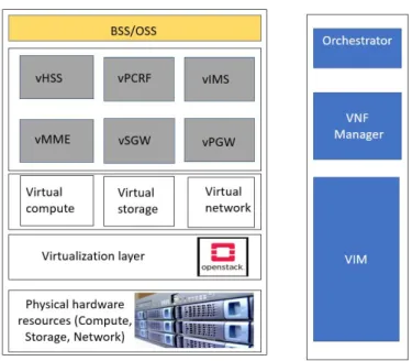
In a telecommunication network, a core network consists of various network elements, and virtualizing core networks can be the first step for operators to move toward network softwarization. In virtualized core network, all the functionalities related to physical network element such as MME, HSS, S-GW, P-GW, etc. are virtualized and implemented as VNF e.g, virtual MME (vMME), virtual HSS (vHSS), virtual S-GW (vS-GW), virtual P-GW (vP-GW), etc. This instantiation of VNF in the cloud provides better performance; hence, VNFs are grouped together based on their interactions and workload. Generally, it is instantiated in each group in one physical server depending on the workload [28]. This will help the operator to decrease vendor dependency and increase the speed of time to market to launch any new services. Figure 8 shows the core network virtualization from the architectural point of view in the LTE network. This is also known as a virtual evolved packet core. In figure 8, all of the functional blocks corresponds to Figure 7 whose functionalities are well discussed above.
Figure 8. vEPC with respect to NFV architecture framework.
2.4 MEC Deployment in vEPC Network
Multi-access edge computing is a key enabling technology which will bring application-oriented services into the edge of the network such that users can explore a wide range of services which requires low latency. MEC technology is expected to be a key technology to be used in 5G, although it can also be realized in 4G networks [5]. Any application that requires low latency or has locality requirements can be run as a software-only entity that runs on top of the virtualization infrastructure. ETSI has proposed a framework for MEC as shown in Figure 9 [29, 30] which are grouped into network level, mobile edge host level, and mobile edge system level:
1. Networks: The networks level consists of external entities such as 3GPP network (e.g LTE, 5G), the local networks, and the external networks as shown in Figure 9. It represents various network access technologies that uses MEC services.
2. Mobile edge host level: Mobile edge host level consists of mobile edge host and mobile edge host level management. Mobile edge host further includes mobile edge platform, mobile edge application and virtualization infrastructure whose functionalities are described below:
• Virtualization infrastructure: It provides compute, storage, and memory resources which are required by MEC applications. The virtualization infrastructure is further responsible for data plane functionality which routes traffic received by MEC platform between applications, services, and network [30].
• Mobile edge platform: The mobile edge platform represents functionalities needed to run applications on a mobile edge host. Mobile edge platform is further responsible for following functions [29, 30]:
– It offers an environment where mobile edge applications can discover, advertise, consumer and offer mobile edge service;
Figure 9. MEC Architectural framework [29].
– It receives traffic rules from mobile edge platform manager, applications, or services;
– Mobile edge platform hosts mobile edge services.
• Mobile edge applications: Mobile edge application runs as VM on top of virtualization infrastructure offered by MEC host. It interconnect with MEC platform and provide related mobile edge services [30]. MEC application support procedures such as lifecycle of application, indicating availability, preparing relocation of user state, etc.
Similarly mobile edge host level management is management entity responsible for managing mobile edge hosts. It includes following entities:
• Mobile edge platform manager: It is responsible for following functions [29]:
– Lifecycle management of applications;
– Provides element management function to mobile edge platform;
– Management of application rules and requirement.
• Virtualisation infrastructure manager: It is responsible for following functionalities [29]:
– It allocates, manages, and releases compute, storage, and networking resources of virtualisation infrastructure;
– Prepares virtualisation infrastructure to run software image;
– Collection and reporting of performance and fault information about virtualised resources.
3. Mobile edge system level: Mobile edge system lies on top of the architecture and it has the overall visibility to the whole mobile edge system. It comprises of following entities:
(a) Mobile edge orchestrator: It is the core functionalities in system level management and its main functions are [29]:
• Maintains overall view of mobile edge system;
• Selects appropriate hosts for applications;
• Application instantiation and termination;
• Application relocation.
(b) Operations support system: It grants request from user to instantiate or terminate applications [29].
(c) User application lifecycle management proxy: It allows UE application to request on-boarding, instantiation, termination of user applications. It also inform UE about state of user applications [29].
ETSI has proposed the following four options to deploy MEC in EPC network which are described below [5].
1. Bump in the wire
In this deployment option, the MEC platform and MEC host can reside between the base station and mobile core network as shown in Figure 10. The overall architecture includes access network, pre-Agg network, IP-Agg network, and core network. Depending on network that is used to access MEC service, it includes local network such as network for enterprise site, hub site, and 3GPP network such as centralized radio access network (CRAN) site. MEC hosts uses local protocol to communicate with MEC gateway which is used to route the traffic to external entities such as PCRF, charging function (CGF), and lawful interception gateway (LIG) using interfaces such as X1, X2, X3, Ga, Gx, Gy, etc. When the MEC platform and MEC are deployed in a single platform then the traffic between MEC application is done locally while GTP encapsulated IP packet is routed to/from S-GW as per PDN. Similarly, when the MEC platform is in the proximity of a radio network or in aggregation node, MEC host will process user traffic GTP packets.
2. Distributed EPC
In distributed EPC deployment scenario, MEC host will include all the EPC components of LTE architecture as shown in Figure 11. The MEC applications can be co-located with EPC functions in the same MEC host and run as VNF. In this architecture, MEC data plate sits on SGi traffic to steer user plane traffic to MEC system. P-GW is responsible for terminating PDN connection and assigning IP address to user in order to resolve MEC application’s IP address [31]. This
Figure 10. Bump in the wire deployment option [5].
option can reduce costs as the EPC and its components can run e.g. as VNFs on the same NFV platform with the MEC components in order to improve scalability and better utilize network resources. This deployment architecture is better suited for mission critical communications [5].
3. Distributed S/PGW
Distributed S/PGW is realised by the network architecture as shown in Figure 12. In distributed S/PGW deployment option, SGW and PGW entities are deployed at the edge site whereas the control plane functions such as the MME and HSS are located at the MNOs core site as shown in Figure 12. 3GPP standard interfaces are used to communicate between each network entities as seen in Figure 12. SGW and PGW network entities are installed as VNF along with MEC application at edge of the network. In this deployment scenario, the MEC host’s data plane connects to the PGW over the SGi interface which is the interface between P-GW and internet. It allows traffic offloading based on APN [31]. Similarly, S1-MME interface is used to handle control plane traffic to handle mobililty management, session management, authentication, etc.
Figure 12. Distributed S/PGW deployment option [5].
4. Distributed SGW with local breakout (SGW-LBO)
The deployment architecture of distributed SGW with local breakout is as shown in Figure 13. In distributed SGW with local breakout deployment scenario, S-GW VNF is co-located with MEC applications VNF in MEC hosts as shown in Figure 13. Standard interfaces are used to communicate between each other as specified in Figure 13. In this deployment mode, S1 bearer is naturally terminated and SGW is enhance to support breakout via network specific traffic filters [31]. With this architecture, the operator can have greater control on the granularity of traffic that needs to be steered [5].
2.5 Micro Core Network
Nokia Micro core network is a lightweight version of EPC developed by Nokia which is targeted to a small private network [32]. Nokia Micro core network solution comprises all or part of 3GPP standards packet core network entities such as MME, HSS, S-GW, P-GW, etc. which are included in compact and modular software solutions. It can be integrated into a small scale server and deployed rapidly. Due to its high availability of features the Nokia Micro Core Network is designed to support critical mission use cases. The solution is easily portable, runs on regular Linux operating system (OS), supports different deployment options in order to fulfill customer-specific needs for performance and capacity. The Nokia Micro Core Network’s operation and maintenance system provides easy provisioning and control of the distributed application system which can be done through a web-based interface. In this thesis, the Nokia Micro core network solution is used as a local breakout to reduce the user plane latency for UAVs test KPI validation.
2.6 5G Test Network
5G Test Network is located at University of Oulu Linnanma campus. It offers unique possibilities for testing 5G technology, components or new services in real time [33]. With its close collaboration with VTT technical research centre of Finland, 5GTN serve most demanding needs for 5G trials. Currently following projects uses the test platform offered by 5GTN [33]: • 5G VIIMA • 5G FORCE • 5G-Enhance • SAT5G • 5G!Drones
Figure 14 illustrates the overall network architecture of 5GTN and location of its network components. It can be seen that there are few remote sites that have been integrated in 5GTN which includes indoor cells at Oulu University Hospital (OYS Health Lab), OAMK Kaukovainio campus, and Caritas Etu-Lyötty. Similarly, Centria Ylivieska macro cells are also integrated to UOulu 5GTN. It can be seen that narrow band internet of thing (NB-IoT) macro is also serving Oulu City centre area from Oulu City Library. UOULU (University of Oulu / CWC) 5G Test Network (5GTN) provides 4G (LTE) and 5G radio access mainly at University of Oulu Linnanmaa campus area. There are few remote radio access sites (LTE/NB-IoT) that are also operational as shown in Figure 14.
It can be seen from Figure 14 that remote sites are connected through S2S virtual private network connections. LTE Macros (B7 and B28 NB-IoT) and 5G NR sites are connected using 10 Gbps links to core and network server cluster. Other sites are connected using 1 Gbps links. Likewise, Centria Ylivieska is connected via Funet multi protocol label switching and current internet connection is accessed using PanOulu
Figure 14. 5GTN network architecture.
public access point (1Gbps). There is also interconnection to VTT’s Oulu site which makes possible for RAN and/or core sharing between UOULU and VTT. Below are the network devices that are being used in 5GTN network:
• 2 pcs Dell N4032
• 1 pcs Dell N4032F
• 1 pcs Quanta LY8
• 1 pcs Juniper SRX240FW
• 1 pcs Juniper SRX1500 FW
Similarly, external VPN connections are done through SRX240 FW or SRX1500. Table 2 illustrates the radio access parameters supported by UOULU 5GTN. Likewsie, Table 3 represents packet core networks installed at 5GTN.
Table 2. Radio access network parameter of 5GTN.
Network Type/Device Frequency band Bandwidth
Macro eNB / Nokia FRHD FDD B7 10 MHz Macro NB-IoT & CAT-M eNB FDD B28 5 MHz
Macro eNB / Nokia FZQE TDD B42 20 MHz Pico eNB / Nokia FW2GHWA FDD B1 + B7 dual band 10 MHz 4G/LTE Pico eNB FDD B7 / Nokia FWHH FDD B7 + B7 / Nokia FW2HHWC FDD B7 FDD B7 + B7 dual radio 10 MHz
5G Macro gNB / Nokia AEQN TDD N78 60 MHz
Table 3. Packet core network at UOULU.
Type Vendor HW SW
CMM (MME) Nokia Airscale CMM19.0.0.2
3 MICRO CORE NETWORK STANDALONE
DEPLOYMENT
In this section, Nokia micro core network solution is used to realize the functionalities of various EPC network entities. The methodology used in this work to achieve thesis objective includes two steps. In first step, nokia micro core network solution is deployed as stand alone operation mode. In second step, reconfiguration and modification is done in MCN solution and its architecture to integrate with 5GTN where MCN acts as local breakout such that it offloads local traffic to MEC server which is described in chapter 4. The main objective of deploying MCN as stand alone mode is to ensure the feasibility and functionality of MCN solution. For this purpose, various network related counters are measured and KPIs are analyzed. In order to perform measurement, MCN is installed by following the standard installation procedure. Then, various network related parameters and IP addresses are configured to ensure end to end connection and full functionality of network. Then the measurement is carried out using test UE.
3.1 System Model
As the first stage of deployment, installation and configuration of Nokia MCN solution in standalone operation mode is carried out. In this deployment model, configuration of MCN as an EPC which includes network entities as MME, S-GW, P-GW, and HSS are done and its functionalities are realized. MCN network entities are basically VMs which are designed for the Kernel based virtual machine (KVM) based virtualization environment. These VMs are deployed in a hardware platform which is known as commercial off the shelf (COTS). In this case, the Nokia Airframe server (Host IP: 10.38.150.3) is used as COTS. Figure 15 shows the hierarchical view of various solution components that are used to deploy MCN as an EPC.
In this deployment architecture, Dell PowerEdge R730 is used as host hardware with Ubuntu 18.04.3 LTS as operating system with single root input/output virtualization (SR-IOV) interface to enable MCN on the host. The installation of MCN is carried out using Nokia installation instructions. After the MCN is installed on top of COTS, IP address as per network model is configured. Figure 16 shows the desired network topology for stand-alone deployment of EPC. It consists of basic network elements which includes eNodeB, HSS, MME, S-GW, P-GW and communicates using standard 3GPP interfaces as described in section 2.2. At the user side 5gtnoulu APN is used to access the data network services. APN is a character string which contains reference to the PDN where desired services are available. APN for any users are defined by operators and network uses it when selecting PGW to setup PDN connection. In Figure 16, core network functionalities are realized by installed MCN as standalone mode of operation.
Figure 16. Network topology for stand alone deployment.
3.2 Network Configuration
In this section discussion about the configuration of network model is carried out. It begins by assigning IP address to various network entities to ensure IP connectivity between them. IP address is a numerical label assigned for devices that are connected to network. IP planning is crucial task when configuring network elements. For this network deployment, following IP parameters as shown in Table 4 has been considered to obtain host address range that will be allocated for network elements.
Table 4. IP address calculation.
Host IP 10.38.150.3 Subnet mask 255.255.255.240 Mask bit 28
Table 5 lists the configured IP address in case of stand alone deployment mode.
Table 5. IP configuration of MCN standalone deployment.
MCN_SA
Network element Interface IP address S1 10.38.150.7 S11 10.38.150.4 MME
S6a From IP pool S1-U 10.38.150.7 S11 10.38.150.12 S5 10.38.150.13 S-GW S5-U 10.38.150.13 S5 10.38.150.14 P-GW S5-U 10.38.150.14
After the configuration of core network, radio parameters are configured. During the attach procedure eNodeB needs to send attach request to MME [19]. Hence, MME IP address is assigned to eNodeB as shown in Figure 17.
Figure 17. IP configuration of MME in eNodeB.
Similarly tracking area code (TAC) is an important parameter in EPC network which needs to be configured in radio network. Tracking area is the logical concept of collection of cells where paging signals are broadcasted and UE can have mobility without updating MME. eNodeB broadcast special tracking area code to notify user which tracking area it belongs. Likewise during attach procedure S-GW selection is based on TAC [34]. Figure 18 outlines the general attach procedure in the network.
• UE initiates attach procedure by sending attach request message to eNodeB. The attach request message has a link to MME and eNodeB forwards attach message to MME.
Figure 18. Basic attach procedure in network.
• Mutual authentication between UE and network occurs after MME initiates authentication request [35].
• MME sends an update location request to HSS and HSS acknowledge by updating UE with its serving MME. MME receives UE’s default subscription (PDN, QoS, etc.) information from HSS or via APN.
• MME identifies S-GW from UE TAC and P-GW from the UE profile. In this network model we have defined TAC=150 which is configured in eNodeB as shown in Figure 19. MME then sends create session request message for default bearer establishment to S-GW. S-GW then forwards it to P-GW.
• Based on APN and QoS, P-GW selects the QoS for EPS bearer and also includes the IP address of UE, which is then responded back to S-GW as create session response message. S-GW further forwards create session response to MME. Finally, MME sends attach accept message to UE via eNodeB.
3.3 Results and Discussion
After the network has been installed and configured testing is carried out using test UE to verify the network performance. The measurement data were taken on 15.4.2020. The complete measurement data is included in Appendix 1 and important results are discussed in this section. APN at test UE is set to "5gtnoulu" as shown in Figure 20. After test UE is connected to network, it can be seen that UE is receiving good signal from
Figure 19. IP configuration of TAC=150 in eNodeB.
TAC=150 as shown in Figure 21 which imply the proper radio network connection. The performance of any network is characterized by its KPIs. 3GPP has proposed standard EPC network KPIs which helps to evaluate network performance [36]. As the deployed network is of small scale and only one test UE was used for measurement, some of the KPIs are irrelevant. However below are the KPIs that have been considered for the evaluation of the network.
1. EPC Attach success rate
Attach procedure is an important part of LTE call flow which is UE initiated procedure to use the related service from the network. Figure 22 demonstrates the attach procedure in stand-alone network deployment via Wireshark logs. Wireshark is a network packet analyzer tool which is widely used for analyzing and troubleshooting network [37]. It provides microscopic details of various messages that are flowing in and out between any two network elements along with message between them. From Figure 22, it can be seen eNodeB (Source IP address = 193.166.28.16) is sending attach request message to MCN (Destination IP address= 10.38.150.7) using S1AP protocol. Upon expansion, the detail message can be seen as "attach request" message. EPC attach success rate (EASR) is the ratio of number of succesfully performed EPC attach procedures to the number of attempted EPC attach procedures for network. It is given by [36]:
EASR =
P
NumberOfSuccessfulAttach
P
NumberOfAttachRequest ∗100% (1)
Number of succesful attaches = 59 Number of attach requests = 59
EASR = 59
Figure 20. "5gtnoulu" APN selection with test UE.
Figure 21. Receiving radio signal from TAC=150.
This implies that network is available for 100% time and UE can access network resource for every attach request.
2. PDN connection Success rate
The PDN connectivity is UE initiated procedure to establish default bearer or dedicated bearer. UE initiates PDN connectivity by sending a PDN connectivity request message to the network. PDN connectivity request is sent along with attach request message as shown in Figure 23 which is collected from wireshark logs. In this procedure, it can be seen eNodeB (Source IP address = 193.166.28.16) is sending PDN connectivity request message to MCN (Destination IP address= 10.38.150.7). Upon expansion, "PDN connectivity request" message can be observed in logs expansion as shown in Figure 23.
PDN connection success rate =
P
Number of successful PDN connection
P
Number of PDN connectivity request ∗100% (3)
Figure 22. Attach procedure in network.
Figure 23. PDN connectivity in network.
Number of successful PDN connection = 59 Number of PDN connectivity request = 59
PDN connection success rate = 59
59∗100% = 100% (4)
This implies the network establishes default bearer connection for users for every attach request.
3. S11 connection establishment success rate
S11 interface refers to the interface between MME and S-GW. As indicated in attach procedure in Figure 18 MME sends attach request to S-GW as also illustrated by Figure 24. While expanding wireshark logs, "create session request" message can be seen which is forwarded by MME (Source IP address = 10.38.150.4) to S-GW (Destination IP address= 10.38.150.12). S11 connection establishment success rate is ratio of number of UE sessions created for S11 create session request to number of S11 create session requests.
S11 connection establishment success rate =
P
no. of UE session created for S11
P
no. of S11 create session requests∗100% (5)
Figure 24. Create session request in network.
Number of UE S11 create session request = 59 Number of S11 create session requests = 59
S11 connection establishment success rate = 59
59∗100% = 100% (6)
Similarly, latency is another important parameter that defines network performance. Latency in its simplest meaning is the time delay between source and destination caused by the network. We have calculated latency between adjacent nodes as well as an end to end latency.
1. Latency between adjacent node
Wireshark is used to capture and analyze internet control message protocol (ICMP) echo traffic to measure latency between adjacent nodes. ICMP message is time stamped and based on time between echo request and echo response, latency between two nodes can be calculated.
• eNodeB and MME
GTP traffic between eNodeB (193.166.28.16) and MME (10.38.150.7) is captured as shown in Figure 25.
Figure 25. ICMP traffic message between eNodeB and MME.
• S-GW and P-GW
Similarly GTP traffic between S-GW (10.38.150.13) to P-GW (10.38.150.14) is captured as shown in Figure 26.
Figure 26. ICMP traffic message between S-GW and P-GW.
Latency between S-GW and P-GW = 61.838548−61.838345 = 0.203 ms
(8)
2. End to End latency
End to End latency refers to total delay caused by network when UE (source) attempts to access some host (destination). Table 6 illustrates the average latency offered by network when connecting to different host for 100 times. The measurement data were taken via "Ping & Net" application [38].
Table 6. End to End UE latency.
no. of ping host average latency (ms)
100 10.38.150.3 34.617 100 10.38.151.67 30.738 100 8.8.8.8 64.137
4 MULTI-CORE NETWORK ESTABLISHMENT
BETWEEN 5GTN AND MCN
4.1 System Model
In this section, discussion about the system model and configuration of micro core network deployment as LBO and its integration with 5GTN is carried out. This mode of deployment is useful for 5G!Drones project where its main objective is to trial several UAV use cases that cover eMBB, uRLLC, and mMTC 5G services and validate 5G KPIs which apply to support such challenging use case. Different trials can be done in remote locations which are delay-sensitive. For delay-sensitive use cases, MEC deployment is a key technology that helps to reduce latency by deploying MEC application on top of the MEC server at the edge of the network as discussed in section 2.4. This architectural framework provides flexibility to deploy micro core networks on the same virtualization infrastructure. MCN VM as LBO is installed using Nokia installation instructions on the same host where MCN standalone VM was installed as shown in Figure 27.
Figure 27. Deployment of MCN LBO in host.
After its installation, MCN LBO as per the desired system model is configured. Figure 28 illustrates the desired network topology for local breakout deployment of MCN and its integration with 5GTN. User can flexibly switch between its desired APN to access required services. When user selects APN-1 i.e., "5gtnoulu", user will be able to use internet services. Similarly, when user selects APN-2 i.e., "5gtnoulumec", user will be able to access MEC applications. This local breakout of user traffic based on APN by selecting SGW/PGW brings the power of edge computing and latency optimization. User then connects to eNodeB via LTE-Uu air interface. eNodeB forwards data plane related traffic to either S-GW of MCN or 5GTN via S1-U interface. Likewise, all the control plane related signalling is handled by the MME of 5GTN. MME selects S-GW of
either MCN or 5GTN via S11 interface. All the data plane related traffic for APN 1 i.e., "5gntoulu" is handled by SGW/PGW of 5GTN and data plane related traffic for APN 2 i.e., "5gtnoulumec" is handled by locally deployed SGW/PGW of micro core network solution. This will ensure any MEC applications installed on the MEC server to be seamlessly used by UE with 5gtnoulumec APN. This system model is 5G ready model which means it can be easily extended with gNodeB at the radio network side.
Figure 28. System model for local breakout deployment of MCN.
4.2 Network Configuration
After the network is installed IP addresses to network elements of the micro core network is configured to ensure IP connectivity between them. Table 7 lists the configured IP address for the desired system model. IP address range has been planned with remaining IP address range calculated from Table 4.
Table 7. IP configuration of MCN LBO.
5GTN EPC and MCN_LBO Network element Interface IP address MME (5GTN) S1 193.166.32.98 S1-U 10.38.150.8 S11 10.38.150.9 S5 10.38.150.10 S-GW S5-U 10.38.150.10 S5 10.38.150.11 P-GW S5-U 10.38.150.11
After configuring core network elements, MME IP address and tracking area details are configured in eNodeB. MME address is defined as shown in figure 29. This will ensure eNodeB forwards attach request to MME of 5GTN.
Figure 29. IP configuration of MME of 5GTN in eNodeB.
Similarly, for this system model, TAC=151 is configured in eNodeB as shown in Figure 30. This will ensure selection of SGW of MCN LBO by MME of 5GTN during gateway selection procedure.
4.3 Results and Discussion
After the setup of network topology and its configuration, network performance is verified using the same approach that was used for standalone deployment case. The measurements data were taken on 15.4.2020. The complete raw data is included in appendix while important parameters and results about network is discussed in this section. APN at test phone is set to "5gtnoulumec" as shown in Figure 31 and proper reception of signal is acknowledged from TAC=151 as shown in Figure 32. The performance of deployed network is then evaluated through some important 3GPP specified KPIs [36].
Figure 31. 5gtnoulumec APN selection in test UE.
Figure 32. Receiving radio signal from TAC=151.
1. PDN connection success rate
PDN connection success rate defines the network ability to successfully assign default bearer to any attach request of users. The PDN connection success rate can also easily reflect attach success rate as both processes occur simultaneously in the LTE network.
PDN connection success rate =
P
Number of successful PDN connection
P
Number of PDN connectivity request ∗100% (9)
Number of successful PDN connection = 30 Number of PDN connectivity request = 30
PDN connection success rate = 30
30∗100% = 100% (10)
This implies the network establishes a default bearer connection for users for every attach request.
2. S11 connection establishment success rate
In this network model, the S11 interface refers to the interface between MME of live 5GTN and S-GW of MCN deployed as a local breakout. Hence, the S11 connection establishment success rate defines the successful connection between the multi-core network. Figure 33 illustrates the general flow of connectivity in the deployed network.
Figure 33. Basic attach procedure in MCN LBO network.
The main difference between standalone and local breakout deployment is the node discovery mechanism. In the local breakout deployment scenario, domain name system (DNS) has been used for gateway discovery [19, 34]. DNS of 5GTN has been configured such that for APN = 5gtnoulumec P-GW of MCN LBO deployment is selected. Similarly for tracking area code = 151, S-GW of MCN LBO deployment is selected. After node discovery attach procedure follows same principle as discussed in section 3.3.
As indicated in attach procedure in Figure 33 MME of 5GTN sends create session request to S-GW of MCN LBO as also illustrated by Figure 34. It can be
seen that MME with source IP address 193.166.32.67 is sending "create session request" message type to MCN LBO S-GW with destination IP address 10.38.150.9 via GTPv2 protocol
Figure 34. create session request in network.
S11 connection establishment success rate is the ratio of a number of UE sessions created for S11 to create session requests to the number of S11 create session requests.
S11 connection establishment success rate =
P
no.of UE session created for S11
P
no.of S11 create session requests∗100% (11)
Number of UE S11 create session request = 30 Number of S11 create session requests = 30
S11 connection establishment success rate = 30
30∗100% = 100% (12)
This implies perfect inter-operation between multi core network environment which is very crucial in seamlessly accessing any MEC application installed on MEC server. Then, latency parameter was analyzed to evaluate the performance of the network. For delay-sensitive applications, latency plays an important role. Hence, adjacent node latency and end to end latency was analyzed.
1. Latency between adjacent node
Wireshark tool has been used to capture echo request and echo response message and latency has been calculated.
• eNodeB and MCN LBO
GTP traffic between eNodeB (193.166.28.16) and MCN LBO (10.38.150.8) is captured as shown in Figure 35 which is captured using wireshark logs. Each message is time stamped and from the time stamp between echo request and echo receive message, latency between two nodes can be calculated.
Figure 35. ICMP traffic message between eNodeB and MCN LBO.
Latency between eNodeB and MCN LBO = 4.983596−4.982799 = 0.797 ms
(13)
• S-GW and P-GW
Similarly GTP traffic between S-GW (10.38.150.10) to P-GW (10.38.150.11) is captured as shown in Figure 36.
Figure 36. ICMP traffic message between S-GW and P-GW.
Latency between S-GW and P-GW = 61.932559−61.932493 = 0.066 ms
(14)
2. End to End latency
End to End latency directly deals with user experience when trying to access network. It provides the total delay caused by network when UE (source) attempts to access some host (destination). Table 8 illustrates the average latency offered by network when connecting to different host for 100 times.
Table 8. End to End UE latency.
no. of ping host average latency (ms)
100 10.38.150.3 44.1 100 10.38.151.67 46.02 100 8.8.8.8 75.05
Comparison of latency between adjacent node in standalone deployment and local breakout deployment shows both have similar latency values. While comparison of Table 6 and Table 8 shows MCN LBO offers higher end to end latency than stand alone deployment. This can be due to the fact that the presence of multiple switches in live EPC network adds on overall latency which is otherwise absent in standalone mode. Similarly, latency from third party application is also function of server on which it is connected and its location can vary overall latency. However, in both cases, latency is under acceptable range.
![Table 1. Minimum technical requirements of 5G [10].](https://thumb-us.123doks.com/thumbv2/123dok_us/10184519.2920950/12.892.170.771.306.672/table-minimum-technical-requirements-of-g.webp)
![Figure 2. 5G network architecture in service based representation [13].](https://thumb-us.123doks.com/thumbv2/123dok_us/10184519.2920950/14.892.211.700.128.380/figure-g-network-architecture-service-based-representation.webp)
![Figure 3. 5G network architecture in reference point representation [13].](https://thumb-us.123doks.com/thumbv2/123dok_us/10184519.2920950/15.892.169.741.258.550/figure-g-network-architecture-reference-point-representation.webp)
![Figure 5. SA architecture deployment [17].](https://thumb-us.123doks.com/thumbv2/123dok_us/10184519.2920950/18.892.286.605.646.930/figure-sa-architecture-deployment.webp)
![Figure 6. LTE Architecture [19].](https://thumb-us.123doks.com/thumbv2/123dok_us/10184519.2920950/19.892.179.755.352.564/figure-lte-architecture.webp)
![Figure 7. NFV architecture [23].](https://thumb-us.123doks.com/thumbv2/123dok_us/10184519.2920950/22.892.159.784.114.619/figure-nfv-architecture.webp)
![Figure 9. MEC Architectural framework [29].](https://thumb-us.123doks.com/thumbv2/123dok_us/10184519.2920950/25.892.121.717.112.650/figure-mec-architectural-framework.webp)
![Figure 10. Bump in the wire deployment option [5].](https://thumb-us.123doks.com/thumbv2/123dok_us/10184519.2920950/27.892.130.756.124.473/figure-bump-wire-deployment-option.webp)
![Figure 13. Distributed S/PGW with local breakout deployment option [5].](https://thumb-us.123doks.com/thumbv2/123dok_us/10184519.2920950/28.892.163.778.923.1095/figure-distributed-s-pgw-local-breakout-deployment-option.webp)
