UWS Academic Portal
Towards an FPGA-Accelerated programmable data path for edge-to-core
communications in 5G networks
Ricart-Sanchez, Ruben; Malagon, Pedro; Salva Garcia, Pablo; Chirivella Perez, Enrique;
Wang, Qi; Alcaraz Calero, Jose M.
Published in:
Journal of Network and Computer Applications
DOI:
10.1016/j.jnca.2018.09.012
Published: 15/12/2018
Document Version
Peer reviewed version
Link to publication on the UWS Academic Portal
Citation for published version (APA):
Ricart-Sanchez, R., Malagon, P., Salva Garcia, P., Chirivella Perez, E., Wang, Q., & Alcaraz Calero, J. M. (2018). Towards an FPGA-Accelerated programmable data path for edge-to-core communications in 5G
networks. Journal of Network and Computer Applications, 124, 80-93. https://doi.org/10.1016/j.jnca.2018.09.012
General rights
Copyright and moral rights for the publications made accessible in the UWS Academic Portal are retained by the authors and/or other copyright owners and it is a condition of accessing publications that users recognise and abide by the legal requirements associated with these rights.
Take down policy
If you believe that this document breaches copyright please contact [email protected] providing details, and we will remove access to the work immediately and investigate your claim.
Towards an FPGA-Accelerated Programmable Data Path for Edge-to-Core
Communications in 5G Networks
Ruben Ricart-Sancheza,, Pedro Malagonb,, Pablo Salva-Garciaa, Enrique Chirivella Pereza, Qi Wanga, Jose M. Alcaraz Caleroa,∗
aSchool of Engineering and Computing, University of the West of Scotland, PA1 2BE bEmbedded Systems Lab, Universidad Politecnica de Madrid, 28040
Abstract
The Fifth-Generation (5G) networks, as the emerging next generation mobile networks, are adopting softwarization and virtualiza-tion technologies as the cornerstones for the network operators to gain significant competitive advantages by reducing both capital and operational expenditure, enabling agile and flexible service creation and deployment, among others. Meanwhile, a virtualized and softwarized 5G network would suffer from downgraded system performance due to this unprecedented paradigm shift towards software-based networking. Addressing one of the top challenges in this context, this paper focuses on improving the performance of the data plane from the edge to the core network segment (backhaul) in a 5G multi-tenant network by leveraging and exploring the programmability introduced by software-based networking. A fully functional prototype has been designed and implemented utilizing a Field Programmable Gate Arrays (FPGAs) acceleration-based platform, and the prototyped system has been empirically tested and evaluated to demonstrate the superior performance enhancements. The proposed solution can effectively support 5G networks in delivering mission-critical or time-sensitive applications such as ultra-high definition video use cases as experimentally validated and shown in this paper, by fulfilling the strict Quality of Service (QoS) requirements imposed to the data plane.
Keywords: Data Path, FPGA, 5G, Mobile Edge Computing, Reconfigurable hardware, Network Architecture and Design
1. Introduction
The emerging Fifth-Generation (5G) networks are expected to achieve superior performance defined in a number of Key Performance Indicators (KPIs). For instance, as far as latency is concerned, the Next Generation Mobile Networks (NGMN) 5
Alliance [1] has defined two relevant 5G KPIs in terms of maxi-mum latency allowed, which are 10ms and 1ms for normal traf-fic and extremely low latency traffic, respectively.
The usage of general-purpose Commercial Off-The-Shelf (COTS) computers at the edge of the network, together with the 10
imposed requirements of softwarization and multi-tenant virtu-alization, implies that a massive portion of the data process-ing of the 5G architecture will be implemented in the software stack, either in the kernel or in the user space of the operat-ing system deployed in these COTS computers. Meanwhile, 15
these requirements are directly against the ambitious 5G KPIs imposed due to the overhead associated to the software and vir-tualization layers in comparison with hardware speed, and it is imperative to address a synergy where hardware and software can work together to face the new challenges introduced by 5G. 20
A 5G network consists of a Radio Access Network (RAN) segment, an Edge segment and a Core segment. This research work is focused on the network that interconnects Edge and Core segments. The Core network segment is typically de-ployed in the data center governed by a cloud computing stack 25
∗
Corresponding author
Email address:[email protected](Jose M. Alcaraz Calero)
allowing multi-tenancy isolation and softwarization, whilst the Edge segment is managed by a mobile edge stack to extend both multi-tenancy and softwarization to this Point of Presence (PoP) of the network. Novel 5G Mobile/Multi-access Edge Computing (MEC) architectures [2] are proposed to deploy ser-30
vices in the last mile, i.e., close to the antenna and the 5G User Equipment (UE), to achieve very low delays, thereby enabling new delay-constrained real-time services.
However, there is a clear need to advance the state of the art and provide hardware-accelerated data path for the much 35
more demanding requirements posed by the 5G architectures deployed on top of multi-tenant cloud infrastructure to achieve the expected 5G KPIs.
When a traditional Network Interface Card (NIC) receives 5G multi-tenant network traffic, it is not able to classify this 40
traffic properly due to the unknown nested encapsulation present in the packet and thus the following consequences take place. Firstly, the programmability of this NIC can not be explored to program the hardware data plane for the 5G multi-tenant net-work traffic to meet security or Quality of Service (QoS) re-45
quirements, and any other value-added requirements that need hardware-acceleration to achieve the ambitious 5G KPIs. Sec-ondly, the NIC is not able to classify the large number of dif-ferent flows that are being aggregated under the same encapsu-lation protocol and thus not able to perform traffic engineering 50
actions over them. Thirdly, features related to network scala-bility such as Receiver Side Scaling (RSS) or Transmitter Side Scaling (TSS) will not work properly since they depend on a proper classification to assign different flows to different CPU
cores to scale up flow management. Our contribution in this 55
paper is focused on overcoming these limitations.
The main contribution of this research work is to provide an insightful understanding of the 5G network communication traffic patterns envisioned between the Edge and Core segments and realize empirical implementation to achieve a hardware-60
accelerated data path based on Field Programmable Gate Ar-rays (FPGAs) for these new communication patterns. The pro-posed framework allows the programmability of the data path directly on the hardware to offload the software stack and thus optimizes the new 5G multi-tenant communication patterns whilst 65
minimizing significantly the delay introduced by software-based solutions. Furthermore, an intensive empirical validation has been performed to demonstrate the viability and scalability of the proposed framework.
The rest of the paper is organized as follows. Section 2 70
reviews the state of the art on existing software- or hardware-based data paths. Section 3 describes the proposed FPGA-accelerated multi-tenant 5G architecture with a detailed expla-nation of the integral 5G elements, especially the cloud-based platform with MEC and the programmable data paths. Subse-75
quently, section 4 presents the technical details on the proto-typing of the novel FPGA-accelerated 5G programmable data path and the various challenges addressed. Section 5 describes the testbed deployed to validate the claims of this contribution and presents both performance and scalability test results to il-80
lustrate our findings. Finally, sections 7 and 8 provide further discussions and conclusions respectively.
2. Related Work
From the data path perspective, virtualization and softwariza-tion adopted by 5G networks introduces multiple encapsula-85
tions to the application traffic and thus extra processing over-head to traffic engineering. Therefore, regarding hardware-based solutions, a pipeline with re-configurable match and action stages appears a promising solution to provide reconfigurable data paths to adapt to the varying traffic patterns [3]. OpenFlow [4] pro-90
vides a fixed non-programmable match and action structure with a close set of protocols and fields to configure a data plane. However, it is getting over complicated in an attempt to cover every possible protocol, whereas new approaches offer frame-works to program the data plane using high-level languages and 95
compiling on a target network card or node, including ClickNP [5], OSDF [6] or Emu [7]. P4 [8] has become an appealing alternative being adopted by academia and industry, as it is a common language for the description of data plane function-alities of different targets. However, not every hardware ar-100
chitecture can support every language option defined in P4, which reduces the portability. Moreover, to add flexibility to describe non-standard elements available in a concrete target, the language provides mechanisms to add external modules to the pipeline. There is an official P4 compiler, P4C, which is 105
target-agnostic and is used as a showcase of the P4 function-alities. P4 requires a target architecture, a structure with fixed elements and programmable modules. The Portable Switch Ar-chitecture (PSA) is a popular target arAr-chitecture that describes
common capabilities of network switch devices, which pro-110
cess and forward packets across multiple interface ports with a pipeline of three input stages (parser, ingress and deparser) and three output stages (parser, egress and deparser). There are multiple compilers available for different target technologies, using the PSA, or a modified version such as FPGA [9], [10], 115
Network Processor Units (NPUs) [11] or Application Specific Integrated Circuits (ASICs) [12].
These reconfigurable solutions have been employed to im-plement multi-tenant programmable support with VXLAN us-ing a NPU [13], ASIC [14] or FPGA [15]. They have been em-120
ployed to implement Long-Term Evolution (LTE) traffic with the General Packet Radio Service (GPRS) Tunneling Protocol (GTP) using hardware-accelerated switches [16]. Moreover, Deep Packet Inspection (DPI) to classify the traffic and selec-tively apply actions to application flows has been implemented 125
over GTP using software solutions [17] and NPU [18]. Regarding software-based solutions, a user-space module used for low-delay filtering of streams available to the mobile user has been proposed [19]. It employs a function on an access router that manages the mobility signaling for a mobile node 130
that is attached to its access link. This approach is implemented within the context of the LTE Evolved Packet Core (EPC) and no multi-tenant isolation is discussed, and thus nested encap-sulation is not considered. Other approaches try to implement GTP decapsulation and re-encapsulation software to allow the 135
use of traditional IP hardware-acceleration [20]; however, this removes the support for user mobility, which is a significant drawback.
Salva-Garcia et al. [21] propose the only framework found in the literature that is able to work in a multi-tenant 5G network 140
data path based on Netfilter, thereby achieving traffic control over Edge-to-Core using a set of hooks inside the Linux kernel to provide callback functions for every packet that traverses the respective hook within the network stack. However, this ap-proach is a software-based solution where the inclusion of new 145
rules leads to an increase of the overall latency for all the traffic passing trough the kernel.
From the hardware side, Attig and Bredner [22] present a programmable FPGA-based parser that achieved high through-put at the cost of high latency. It uses a simulator to validate the 150
operation of the Xilinx Virtex-7 FPGA employed. The work fo-cuses mainly on nested tagging protocols (VLAN and MPLS) but lack of support for nested encapsulation headers. Conse-quently, that solution is not suitable for the 5G Edge-to-Core network segment concerned in our work. In [23], an FPGA-155
based parser has been implemented using Xilinx Virtex-7 in an SDN architecture. Better performance results are reported compared with [22] in terms of latency but the solution does not provide support for nest encapsulation of 5G traffic either.
In [24], a hybrid hardware-software solution proposes a way 160
to increase the performance in 5G mobile traffic. This solu-tion employs DPDK [25] yet only leverages software acceler-ation to classify 5G packets between the different CPU cores using a hashing function to identify the correct worker core. Although the solution in [24] presents excellent values in terms 165
4 times slower than our hardware acceleration based solution presented in this paper.
The solution in [24] is tested in a real 5G edge-core en-vironments; however, the work does not provide any scheme 170
to control traffic in the network, which in turn imposes a sig-nificant penalty in overhead in contrast to our research work. Therefore, in that solution no performance analysis has been carried out through performing real flows control and manage-ment. Our solution instead provides a REST API that allows 175
flows control and management to be programmed in hardware to avoid increasing in latency. Our solution has also been tested in a real 5G environment, and moreover in our case, we have tested the environment using 4K Ultra High Definition (UHD) videos and inserting and removing rules to adapt the quality of 180
the video to the requirements of the 5G users.
Despite the above advances in the state of the art, there is no existing hardware-accelerated solution that is able to sup-port the nested encapsulation introduced by 5G multi-tenant networks whereas allowing programmable traffic control. This 185
gap in the state of the art has been the main motivation for this research work, which provides a prototype of a FPGA NIC with nested encapsulation support for hardware acceleration suitable for 5G Edge-to-Core network segments.
3. Proposed FPGA-Accelerated Multi-Tenant 5G
Architec-190
ture
This section describes our proposed architecture to achieve an FPGA-accelerated multi-tenant 5G network data path for the Edge-to-Core network segment.
3.1. Architecture Overview
195
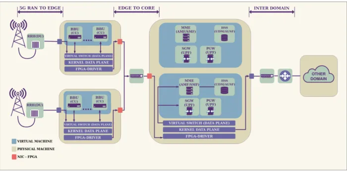
Figure 1 depicts an overview of a 5G infrastructure that has been deployed in our premises using a MEC architecture based on OpenStack with multi-zone support. Figure 1 shows diff er-ent architectural componer-ents and network segmer-ents associated to different geographical locations. The management node and 200
network with the OpenStack Controller has been omitted for the sake of simplicity. The fronthaul defines the segment between the UE and the Remote Radio Head (RRH) located on the top of the mast and attached to antennas. To reduce costs, 5G net-works are expected to be based on a Cloud-RAN (C-RAN) [26] 205
deployment where multiple RRHs are connected to a pool of BaseBand Units (BBUs) through optical fibres. In a MEC ar-chitecture, these BBUs are deployed in the last mile, close to the UE to allow also the deployment of fast processing data services collocated with the BBU at the edge of the network. The 5G ar-210
chitecture is based on the functional desegregation of all the ex-isting 4G/LTE services to allow a flexible deployment of such functionalities in different network segments according to the requirements of the customers. Thus, to represent graphically this functional desegregation, RRHs and BBUs are usually de-215
picted in 5G terminology as Distributed Units (DUs) and Cen-tralized Units (CUs) to indicate that the roles of these units will depend on the specific deployment [27]. The deployment in our
premises uses OpenAirInterface [28] as part of the LTE/5G in-frastructure deployed using Ettus B210 [29] Software-Defined 220
Radio and SIM Cards from SYSMOCOM [30].
This paper focuses on the network segment between the edge and the core. This network segment is governed by Open-Stack to allow multi-tenancy isolation of the different virtual machines (VMs) that are deployed at either the edge or the core 225
network locations. This multi-tenancy is achieved at the pro-duction stage using either a tagging protocol such as VLAN or an encapsulation protocol such as VXLAN, GRE or Geneva, depending on if the cloud provider allows its customer to have software-defined networks or not. This encapsulation is imple-230
mented currently either at software layer using a virtual switch such as Open VSwitch (OVS) [31] or at hardware layer using Single Root I/O Virtualization (SR-IOV) [32] with VLAN tag-ging support, or similar technologies. This multi-tenancy sup-port allows the sharing of the same physical resources by em-235
ploying virtualization and encapsulation between different ten-ants (typically corresponding to different operators) whilst im-posing this encapsulation requirements. Our deployment em-ploys OVS v2.6 [33].
The LTE Serving Gateway (SGW) has been functionally 240
disaggregated into the User Plane Function (UPF) in 5G, act-ing as a mobility anchor of the communications for all the users towards the core network. The communications between BBU and SGW represent all the uplink/downlink traffic sent/received by the users that are not connected to the same antenna. These 245
communications are encapsulated using the GTP protocol, mainly to allow the management of the mobility of the users across the different antennas in a transparent way without losing con-nectivity while a user is being handed over between different RRHs. This encapsulation is applied by both ends of the data 250
path, i.e. BBU/CU and SGW/UPF. It is important to note that the merging of both 5G and MEC architecture in a production-ready environment will entail the usage of a network traffic pat-tern with double encapsulations to support both multi-tenancy and user mobility simultaneously. It is expected to have traffic 255
with GTP over VXLAN and GTP over GRE along this Edge-to-Core network segment. GTP encapsulation is performed by the BBU/CU and SGW/UPF software services whereas VXLAN [5]/GRE [6] encapsulation is performed by the virtual switch. After these double encapsulation is performed at various stages 260
along the data path, the packets are sent to the Linux kernel stack and then to the NIC using Direct Memory Access (DMA) by its driver and finally processed by the NIC to be delivered to the other end, either Edge to Core or vice versa.
A new FPGA-based NIC prototype is devised in the pro-265
posed architecture to enable the experimental programmability of the hardware data path. This new prototype demonstrates the suitability of the proposed support for the novel classifica-tion of the 5G traffic within the double encapsulation to allow the programmability of the 5G multi-tenant data path between 270
the Edge and Core network segments. The following subsection presents this FPGA-based NIC prototype.
Figure 1: Overview of the proposed FPGA-accelerated multi-tenant 5G architecture
3.2. Data Path Hardware/Software Framework
Figure 2 shows the architecture of the FPGA-based data path prototype. The FPGA-based NIC used as a reference to 275
implement the proposed prototype is the NetFPGA SUME [40]. This programmable FPGA NIC provides 4 x 10GbE ports and 1 DMA port (for NIC-to-Kernel communications) that are later connected to Rx and Tx queues to homogenize the different clocking times.
280
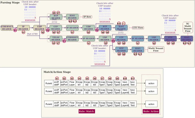
Figure 2: Pipeline of reference P4 NIC hardware/software data path.
As shown in Figure 2, all the packets being received in the RX Queues are served using a Round-Robin algorithm imple-mented into the Input Arbiter to the P4 Pipeline. As a reference prototype, it has employed the P4 NetFPGA reference imple-mentation recently released by the NetFPGA Team [34] using 285
the Xilinx SDNet P4 compiler [35]. This generic P4 pipeline is composed by three sequential stages: Parsing, Match/Action and Deparsing. The role of the parsing stage is to provide a custom packet classification capability to extract all the de-sired information of the packet. The role of the Match/Action 290
stage is to allow the programmability of the actions to be con-ducted over the packet by matching the extracted information in the parsing step against values stored in a lookup data struc-ture. Finally, the role of the Deparser stage is to reconstruct the packet (if required) following the actions indicated by the 295
Match/Action step and thus sends it into the Output Arbiters. The output Arbiter places the received packets into the appro-priate TX queues following the indication received by the De-parser. If the packets are intended to be received by the com-puter where the NIC is installed, they follow the DMA path, 300
which performs a direct copy of the packet in RAM, using the PCIe v3.0 interface, and then notifies the NIC FPGA-driver of the reception of the packet to allow the process of the packet in the kernel of the operating system.
3.3. Proposed 5G Multi-tenant P4-Based Data Path
305
The data path proposed mainly acts in the first two stages of the NetFPGA P4 pipeline: Parsing and Match/Action. Fig-ure 3 shows the logical representation of the two stages of the pipeline that have been designed in our prototype to provide na-tive support for the double encapsulation required in the Edge-310
3.3.1. Parsing Stage
Regarding the P4 matching stage (the upper part of Fig-ure 3), a specific P4-based program has been developed to al-low the desegregation of IP fal-lows, LTE/5G flows, multi-tenant 315
VXLAN flows and 5G flows nested in multi-tenant VXLAN flows, respectively. These flows arrive as incoming packets at the pipeline and they are processed using a data-driven gramming approach where every header is sequentially pro-cessed to extract the key interested values that are going to be 320
used to apply rules in the Match/Action stage and to determine what is the next header to be processed based on key header fields available in the headers. For example, to move from Eth-ernet Header to IP Header (P1 in Figure 3), the field Ether-Type of the Ethernet header is checked against the hex value 325
0x0800 indicating that the next header type is IP. To identify the encapsulation protocols that are supported in this pipeline, a lightweight approach has been designed to check mainly the UDP port value (P2 in Figure 3) against their standard usage in-dicated by IANA [36] rather than going for more complex DPI 330
approaches in order to minimize delay. This approach allows classifying GTP and VXLAN, which are the main protocols implemented to validate our design. Specifically, VXLAN uses UDP 4789 whereas GTP uses UDP 2152. It allows continu-ing the parscontinu-ing of the packets into the tenant network in case 335
of VXLAN or into the UE network in case of GTP. 5G net-works will impose the usage of both VXLAN and GTP, one over the other; therefore, this identification process of encapsu-lation protocols is performed for various times along the pipeline in order to allow a really fine-grained definition and desegrega-340
tion of traffic per tenant and per user. It is noted that after the first UDP header (P2 in Figure 3), the encapsulation ID is ex-tracted from the encapsulation protocols. This ID has the main purpose of identifying a specific set of traffic. For example, it is used to tag the tenant ID in case of the MEC multi-tenant ar-345
chitecture (K4 in Figure 3) and to tag the UE traffic in case of the 5G architecture (K5 in Figure 3).
The Real-Time Transport Protocol (RTP) is used to mul-tiplex different audio and video traffic within the same flow, allowing the video/audio player to have synchronized informa-350
tion to be played in real time. This protocol has been added to this design to provide support for the use case that has been prototyped in the empirical validation. RTP will stress even more the design since it provides another level of flow deseg-regation where different audio and video flows are multiplexed 355
in the same network flow. In summary, key values are extracted from RTP and its payload to identify to which video/audio sub-flow this packet is associated within the same RTP sub-flow. K6 in Figure 3 indicates where the RTP payload is extracted to iden-tify the type of sub-flow, and K10 and K11 indicate where the 360
video quality and temporal layers IDs are extracted to know what quality and temporal layers a video flow are associated to, respectively. These video layer meta-data are extracted from the Scalable H.265 video codec [47], [48], which is the latest video codec, to determine which layer can be removed to re-365
duce the resolution or the frame rate of a given video flow to be able to adapt the video in network congestion conditions by
removing less important video layers (more details in section 5). One of the challenges associated to the classification of the RTP is that DPI needs to be performed to identify correctly that 370
the payload is an RTP payload. To this end, an adaptation of the DPI classification algorithms for RTP implemented in nDPI [37] is explored to check the value of the first 6 bytes of the pay-load against a specific mask shown in Figure 3. RTP has been implemented in the same way as it is considered as a special 375
type of encapsulation protocol (for video traffic). It will vali-date an architecture where even triple encapsulation is present (i.e., RTP over GTP over VXLAN).
Regarding the approach for parsing encapsulation, it is noted that K4, K5 and K6 in Figure 3 appear more than once in Fig-380
ure 3. This is because the information about these headers can be extracted from different parts of the packet depending on the number of encapsulation protocols that are present in the packet. Thus, to deal with this dynamic nature, it has been de-cided to create three extra fields of meta-data that indicate what 385
is the encapsulation type associated to that value extracted. This provides the semantics of such a value (K7, K8 and K9). These meta-data take the values of VXLAN, GTP or RTP in order to provide the semantics of the values stored (K4, K5 and K6). This is a clear extension to the state of the art to allow the sup-390
port of nested protocols. This dynamism in the classification of the packet is a clear differentiating point of our proposal with respect to traditional firewalling/filtering appliances that do not allow more than one occurrence of the headers.
Regarding the approach for parsing the IP addresses, it is 395
noted that K1 appears more than once in Figure 3. This is be-cause the information about this header can be extracted from different parts of the packet depending on the number of en-capsulation protocols present in the packet. Consequently, the semantics is completely different, and every IP header detected 400
will override the value of the previous IP header extracted so that at the end of the parsing, only the most inner IP header information will remain available in the meta-data extracted.
It is noted that the support for these three different types of encapsulation in any order together with the extraction of the 405
most inner IP header information allows the NIC to classify and perform actions over every video layer delivered/received from a UE moving between antennas. These antennas can belong to different tenants of the MEC architecture, where the traffic is isolated to enforce isolation between tenants while they share 410
the same computational resources. This capability allows the definition of fine-grained rules in the Edge-to-Core segment, which has never been supported before.
In Figure 3, three different names are used to refer to the flows according to the number of encapsulation protocols as-415
sociated, namely, IP Flow, Multi-tenant Flow (VXLAN), LTE Flow (GTP), and 5G Multi-Tenant Flow (GTP over VXLAN). These names will be used in the rest of the paper to refer to different packet traces (traffic patterns). It is noted that K3 in Figure 3 is the only value that is used in the rule, but it is not 420
extracted from the packet. This is a counter that is increased ev-ery time when there is a new encapsulation header. It will match the values 0, 1, 1 and 2, respectively, with these four types of flows described. It allows determining the mask used in the
ac-Figure 3: Design of the 5G multi-tenant match/action data path
tion stage to be calculated dynamically rather than statically as 425
happening in most of the architectures today.
As addressed in [38], the inclusion of nested encapsula-tion fosters packets fragmenting, as there are several IP lay-ers. There is no existing standard strategy for fragmentation in this scenario. Our solution provides mechanisms to detect frag-430
ments at any of the encapsulation layers, providing coherence in the decisions made over a packet to all its fragments.
3.3.2. Match/Action Stage
Once the parsing stage has been performed, all the meta-data are extracted from the packet and then shared with the 435
Match/Action stage. In fact, in the lower part of Figure 3, it can seen that the structure of the designed rule to clearly iden-tify what are the key field extracted from all the headers along the way, e.g., IP addresses, encapsulation IDs, encapsulation types, UDP/TCP ports, and video layer information. These 440
meta-data are used to match the extracted information against a list of rules stored in a data structure, allowing fast match-ing and recovery of the positive matchmatch-ing. If there is a posi-tive matching, the first matching result will provide the action to be conducted over the packet. Currently, three different ac-445
tions are designed, useful in the context of the Edge-to-Core segment: DROP packet, L1 MIRROR packet and L2 REDI-RECT packet, allowing implementing several use cases such as selective monitoring [39], self-protection [40], intrusion re-sponse systems [41] and video optimization [21], among others. 450
Table 1: Functions to control ternary lookup tables
End Point Description
/add Adds a new rule in a table
/delete Deletes a rule of a table
/clean Deletes all the rules of a table
/numRules Returns the total of rules
The usage of a list of rules implies the creation of a con-trol channel to allow the insertion, deletion and update of rules into the data structure. To allow this functionality, the design explores the support from the P4 compiler project provided by the NetFPGA SUME prototype used. It allows the user to in-455
voke an API to populate this list of rules from the user space of the operating system where the FPGA NIC is installed. A new API has been developed to enable the development of the scenario described before. It allows the control of the Ternary Content Addressable Memory (TCAM) tables where the rules 460
are stored in the NetFPGA. The main functions are depicted in Table 1. The/add function of the API receives both matching and mask parameters to define the rule and the part of the rule that needs to be matched, together with the action to be per-formed in case of matching. This API allows the exposure of 465
the control to enable the usage of the prototype in an SDN de-ployment where an SDN controller controls the rules along the data path.
4. Implementation
The selected framework for the based development of the 470
proposed solution is the NetFPGA platform using the P4-NetFPGA compiler. This solution uses the NetFPGA Simple SUME Switch architecture, similar to NetFPGA PSA yet simpler. The reason why the NetFPGA has not been compared with other COTS cards is due to the expensive nature of FPGA cards in the cur-475
rent market and the lack of support for matching tables in exist-ing COTS cards. The goal is to provide just enough features so that it is an effective prototyping tool. The implemented P4 represents exactly the design described in Section 3. The communication between the PC and the FPGA NIC is through 480
PCIe, using the RIFFA framework [42], with support for PCIe v3.0. The RIFFA framework for NetFPGA is configured with one DMA engine of two bidirectional channels: one for pack-ets and the other one for registers and configuration. On the PC side, the RIFFA driver configures one single PCI Base Ad-485
dress Register (BAR) and one interrupt for the communication, with support for four Ethernet interfaces (from nf0 to nf3). The Ethernet interfaces are linked to the packet channel, while ioctl calls are linked to register read/write and configuration. The framework provides an API and CLI to perform configuration 490
operations from the user space to fill up tables and read/write registers.
Our solution uses tables to define the rules to perform ac-tions on the encapsulated packets, using the values of specific fields of the incoming packet as key and specifying the rule 495
ID and action to be performed as values of the table. In P4 NetFPGA, the tables are implemented using a pair of memory blocks: a CAM for the key detection and a RAM for storing the value. Depending on the capabilities associated to the matching pattern, the framework allows the selection of a regular CAM 500
with exact matching pattern or a TCAM with ternary matching pattern support. Both CAM and TCAM allow a very fast re-trieval of the first positive match of the given key against all the rules stored in the data structure. The main difference between them is that CAM forces an exact matching of all the fields that 505
compose the key, whereas TCAM allows enable and disable if a field composing the key needs to be considered as part of the matching or not. It enables a significant flexibility in the design of the rules since now we can use wild cards in the definition of the rules to allow ANY semantics. For this reason, the pro-510
totype implemented has selected TCAM, using the Xilinx 1151 Application Note [43]. The regular CAM can be implemented using the reconfigurable LUT as shift modules (SRL16E) or us-ing dedicated memory modules (Block RAM), both performus-ing the reading in one clock cycle. The main differences are that the 515
former requires 16 clock cycles for writing while the latter re-quires only two, and that the former uses reconfigurable logic that cannot be used for the P4 program logic. The TCAM can only be implemented using shift modules, reducing the amount of reconfigurable logic available for a P4 program. Our solution 520
requires ternary tables to enable rules for the different encapsu-lation levels, considering different wild card usages depending on the scenario (optionally considering IP addresses at the dif-ferent encapsulation layers, ports or application level headers).
Moreover, in a multi-tenant 5G scenario, there are packets with 525
different encapsulation layers coexisting and thus the rules re-quire the flexibility provided by ternary tables to ignore encap-sulation layers that are not available.
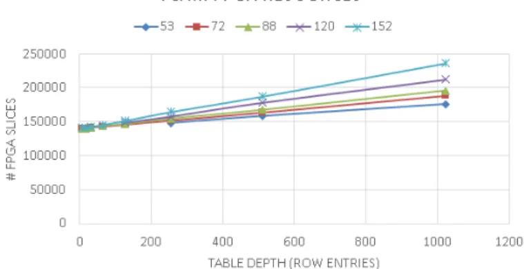
Figure 4: Slices used for TCAM.
Figure 4 shows the linear relation between key size, table depth and reconfigurable logic resources needed. We have se-530
lected a key size of 152 bits and a depth of 512, which allows us to insert 512 rules with different actions associated to each of them. Prior to the development of this data path for the NetF-PGA, an efficient architecture needs to be designed, based on the TCAM implementation, to allow the identification of the 535
5G traffic. We have implemented three P4 programs for dif-ferent NIC capabilities regarding the different traffic flows: an IP flow, a Multi-tenant flow (VXLAN), and a 5G Multi-tenant flow (VXLAN/GTP) supporting DPI at the application layer for video traffic over RTP classification. Nevertheless, the P4 pro-540
gram that supports 5G Multi-tenant flows is also able to support IP flows; in the same manner that the program to process 5G tenant flows is also able to process IP flows and Multi-tenant flows. The TCAM has been meticulously designed due to the fact that the storage capacity of the NetFPGA is strongly 545
limited. As represented in Table 2, 98% of the resources have been used to develop the solution that supports the three types of flows. For this reason the selection of the keys shown in the Match/Action stage of Figure 3 has been carefully studied to select the lower number of fields that allow the detection of a 550
specific flow.
Table 2: NetFPGA resources used in hardware implementation
IP VXLAN VXLAN/GTP
Slices 55150 (51%) 74711 (69%) 106734 (98%)
BRAM 575 (39%) 793 (54%) 1240 (84%)
5. Empirical Validation
This section empirically validates the proposed approach, demonstrates the suitability of the proposed architecture for the 5G Edge-to-Core network segment, and provides an analysis of 555
In addition, we evaluate the delay results to show how the pro-posed solution fulfills the 5G KPIs in terms of E2E latency.
5.1. Use Case Addressed
A realistic use case has been prototyped to empirically val-560
idate the effectiveness of our proposed architecture. In this use case, five 4K Ultra High Definition (UHD) videos are trans-mitted sequentially from a 5G UE to a server located in the Internet, outside of our administrative domain. In the commu-nication, the video flows traverse from Edge to Core through 565
our based prototype, and then to Internet. The FPGA-based prototype is programmed to recognize and process the 5G multi-tenant traffic pattern. It is noted that the videos are encoded using Scalable H.265 [44], [45], which employs a lay-ered coding mechanism to allow priority-based scalability in 570
spatial, temporal or other dimensions. In Scalable H.265, the base layer video has the highest priority to be delivered, and ad-ditional enhancement layers can be discarded e.g., in response to network congestion.
In the testbed, the videos are encoded with two spatial video 575
layers in 2K (based layer) and 4K (enhancement layer) reso-lutions respectively. The FPGA prototype is programmed to recognize and then drop the 4K video layer of all the video flows. This use case has significant implications since it is ex-pected that 90% of traffic in Internet will be video traffic in 580
2020 and 5G is not an exception [46]. The dropping of less important video packets from a video stream is a typical adap-tation mechanism to deal with transmission constraints such as network bandwidth limitation caused by traffic congestion.
When the traffic is passing through the network segment 585
between Edge and Core, three different encapsulation scenar-ios are analyzed. Firstly, a traditional IP network with no en-capsulation is set up to establish a reference baseline for com-parison. This scenario employs a network traffic stack defined as MAC/IP/UDP/RTP/VIDEO Layer Payload. Secondly, a 590
MEC scenario has been analyzed where multi-tenancy has been employed to isolate tenant traffic. This scenario is defined as the following network stack: MAC/IP/UDP/VXLAN/MAC/IP/ UDP/RTP/VIDEO Layer Payload. Finally, to achieve a per-formance evaluation in a 5G multi-tenant infrastructure, both 595
VXLAN tunneling for tenant isolation and GTP for UE mobil-ity across different antennas are included. This scenario adopts a network traffic stack defined as MAC/ IP/ UDP/ VXLAN/ MAC/IP/UDP/GTP/IP/UDP/RTP/VIDEO Layer Payload.
To achieve reproducible lab conditions, the video transmis-600
sion for the double encapsulation is first sent from a 5G UE using an architecture analogous to the one depicted in Figure 1, currently deployed in our lab, as part of our roadmap to achieve a 5G trial in our premises. Then, a PCAP (Packet Capture) file is generated from this infrastructure to allow us to scale up the 605
number of flows using PCAP processing tools, and to remove the encapsulation to gather comparable yet simplified scenarios such as the simple encapsulation (Multi-tenant flow) or the one with no encapsulation indicated (IP Flow). These PCAP files are then used in our experimental setup to validate both the per-610
formance and scalability achieved in the prototype.
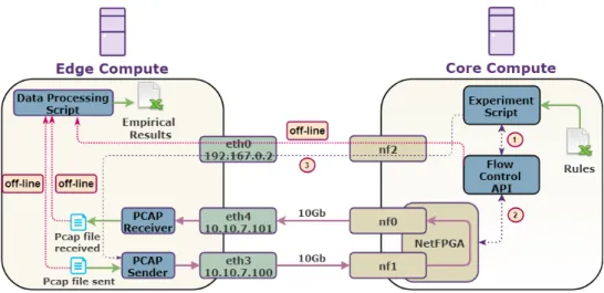
5.2. Experimental Setup
Figure 5 depicts the experimental testbed constructed to carry out the empirical validation of the proposed framework. Both Edge and Core Cloud Compute share the same hardware spec-615
ifications: Dell T5810, Intel Xeon CPU E5-2630 v4 2.20GHz, 32768 MB RAM, and 512 GB SDD. In terms of network cards, the Edge compute has a Gtek MLX-6801-1S 10GbE NIC with 2 x 10GbE Interfaces whereas the Core compute has a NetFPGA SUME [47] with 4 x 10GbE Interfaces. The NetFPGA has been 620
programmed with the pipeline with support for 5G Multi-tenant flows and all the experimental results have been gathered using such FPGA bitstreams.
The testbed is governed by an Experiment Script that ranges the number of 5G video flows to measure scalability, packet 625
size, packet rate and the type of video flow (IP flow, Multi-tenant flow, 5G Multi-Multi-tenant flow) to measure performance in terms of delay, packet loss and throughput. Table 3 shows the ranging values of each of the different dimensions empirically analyzed.
630
For each of the scenarios analyzed, the Experiment Script inserts the rules associated to the scenario that is going to be processed (see 1 and 2 in Figure 5). There is a maximum of one rule per video flow and the main action associated to the video flow is to drop the enhancement layer of the video flow. 635
Later, the Experiment Script starts a tcpdump in the receiver in-terfaces in the Edge side and after that starts sending the PCAP to the Core compute (see 3 in Figure 5). The FPGA NIC is programmed with the proposed framework. Packets are sent from the Edge and received in the prototyped network card in 640
the Core network segment and all the packets related to the en-hancement video layer are then dropped. The rest of the packets are sent to the FPGA driver of the Core compute, reaching the Linux operating system and thus the VMs running there. All these packets will be mirrored by default to another NIC inter-645
face of the FPGA. This mirroring is an artefact designed in our testbed with the main intention to be able to measure end-to-end network delay using a common reference clock. Then the pack-ets are received back to the Edge compute and stored in a PCAP to be later processed in a batch mode off-line. This saving of 650
both sent and received PCAPs is only used to later on calculate the delay using the same clocking reference. The measurement of packet loss and throughput do not require the usage of this artefact. This process has been executed five times in order to show statistical significance. One hop has been deployed be-655
tween the Edge and Core, as a realistic scenario where CU and UPF will be deployed.
After the scenarios are executed, all the PCAPs are stored in the Edge computer. Then, the Data Processing Script is exe-cuted to analyze both the sent and received PCAPs, calculating 660
end-to-end delay, the number of packet dropped, and bandwidth saved due to the application of the rules. The empirical results achieved in this testbed are described in the following subsec-tions. Different experiments have been carried out as described in the following subsections.
Figure 5: Testbed for empirical results over the prototyped architecture.
Table 3: Testing parameters
Dimension Min Max Steps
# 5G Video Flows 1 512 1, 2, 4, ..., 512
MTU 150 1500 150, 200, 250, 300, 400, 500, ..., 1500
Bandwidth (Mbps) 1000 10000 1000, 2000, ..., 10000
Type of Flow IP 5G Multi-tenant IP Flow/Multi-tenant Flow/5G Multi-tenant Flow
# Rules 0 512 0, 1, 2, 4, ..., 512
5.3. Pipeline Evaluation Test
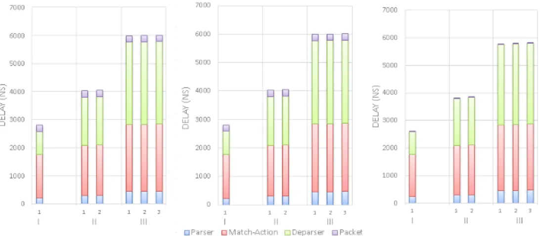
The main purpose of this section is to validate the proposed design by analyzing the delay introduced in the pipeline due to the extra logic required to provide support for the classification of the different encapsulation layers present in the packets. Fig-670
ure 6 plots an analysis of the delays for the different bitstreams programmed in the NIC. Three different bitstreams have been programmed in the NIC with support (1) only for IP flows, (2) for IP flows and VXLAN flows, and (3) for IP flows, VXLAN flows and 5G Multi-tenant flows, respectively. Then, for each 675
of the programmed bitstreams, different PCAP files have been inserted in the pipeline to examine their difference in terms of delay at line rate speed of 50 Gbps for the pipeline. Figure 6 shows a white box analysis where the three main stages associ-ated to the P4 pipeline are measured in terms of delay. More-680
over, there is a fourth time measured directly related to the size of the packet, since the width of the P4 bus is 256 bits and thus only this number of bits can be processed in each of the cycle. Thus, for longer packets, there is an extra delay incurred due to the fact that they are crossing the pipeline. As can be seen 685
in Figure 6, there is almost no difference in delay between the usage of one rule and the usage of 512 rules. This is mainly due to the key features associated to the usage of the TCAM struc-ture (the left sub-figure in comparison with the sub-figure in the centre of Figure 6). Furthermore, there is a delay of less than 690
100 nanoseconds (ns) between very long packets (1500 bytes) and the shortest ones for double encapsulation (144 bytes) un-der the same conditions (the left sub-figure in comparison with the right sub-figure of Figure 6). The reason of this tiny delay is related to the fact that the implemented pipeline is able to 695
process only 256 bits in each cycle and thus it will require more
cycles to process longer packets.
In addition, it is noted how the reference NIC only suit-able for IP Flows requires around 3 microseconds to process the packet in the pipeline. In contrast, the NIC with support for 700
single encapsulation (multi-tenant flows) requires 4 microsec-onds leading to a 1 microsecmicrosec-onds of overhead in the pipeline to support this functionality. For the case of the support for dou-ble encapsulation, 6 microseconds are required to process the packet in the pipeline, i.e. there are 3 microseconds of over-705
head in the pipeline to support this 5G classification functional-ity when compared with the reference NIC. It is noted that any of the NIC implemented in this experiment behaves exactly the same for all the flow types that they support, as can be seen in the grouped bars shown in the figures. These results demon-710
strate significant effectiveness achieved in the programmability of this advanced processing of the pipeline for 5G Multi-tenant support. Table 4 shows the specific numerical values plotted in Figure 6.
This 3 microseconds of overhead of the proposed solution 715
contributes minimally to the E2E latency by adding only 0.003% to the 1ms 5G latency KPI imposed by NGMN; meanwhile, in reward, this minimal overhead enables us to achieve pro-grammable traffic control capabilities over a new infrastructure with user mobility and tenant isolation, leading to improved in-720
frastructure protection and access control, traffic engineering, QoS management, etc. It is noted that current reference NIC only provide some of these capabilities for pure IP network and not for 5G multi-tenant networks.
Figure 6: Analysis of delay in the pipeline for the different bitstreams programmed in the NIC versus the type of flow being processed in the NIC. (Left) 1 Rule and 1500 bytes packet size, (Center) 512 Rules and 1500 bytes packet size; (Right) 1 Rule and 144 bytes packet size.
Table 4: Analysis of the delay results plotted in Figure 6 (in microseconds) about the pipeline of the different bitstreams programmed in the NIC against the types of flows supported for each bitstream.
IP Flow 5G Flow 5G Multi-tenant
Flow 1 Rule, 1500 MTU 2,9 4 6 512 Rules, 1500 MTU 2,9 4 6 1 Rule, 144 MTU 2,8 3,9 5,9 5.4. Performance Test 725
The performance experiments have the main aim to empiri-cally validate and evaluate the prototype in different conditions using the testbed described in section 5.2. The results obtained in this paper are not empirically compared with other solutions due to the fact that there is not any other FPGA cards in the 730
market with programmable 5G Edge-to-Core support yet and thus no results can be obtained.
As initial testing, sending bandwidth is linearly increased with no rules inserted in the TCAM structure to focus on the evaluation of the NIC performance. The intention is to mea-735
sure the evolution of the end-to-end round-trip delay, packet loss and throughput, whilst the packet size is linearly decreased from the Ethernet Maximum Transmission Unit (MTU), which is 1500 bytes. This experiment is carried out against the three types of flows considered: IP Flow, Multi-tenant Flow and 5G 740
Multi-Tenant Flow, to analyze the behavior of the implemented P4 pipeline for the Edge-to-Core 5G multi-tenant flows under different PCAPs.
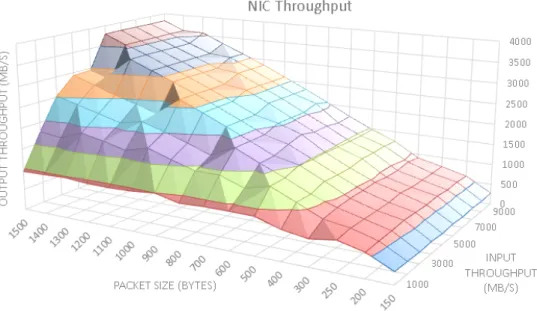
The first aspect to analyze is the maximum throughput that can be achieved using the standard Gtek Mellanox ConnectX-2 745
MLX-6801-1S 10GbE NIC to send and receive PCAPs from the NetFPGA card with the latest version of the Mellanox Linux drivers provided for the card, v.4.2-1.0.1.0 [48]. To do so, an iperf stress test has been carried out using a loopback inter-face and tcpdump to store both sent and received PCAPs. The 750
PCAPS are stored on a fast PCIe SSD-drive Toshiba THNSN 5512GPU7. As a result, we have empirically measured the
maximum throughput achieved in our testbed to be up to 3,8 Gbps, as depicted in Figure 7. Beyond this throughput, the net-work card starts to drop packets in the transmission and then 755
the network conditions cannot be measured accurately. More-over, the 3,8 Gbps throughput is further reduced to 3 Gbps due to the employed packet capturing. This is the reason why all the experiments range speeds up to 3 Gbps, a practical maximum throughput, even with a nominal 10 Gbps interface. Moreover, 760
the throughput is largely dependent on the size of the packets used in the experiment, mainly due to the number of interrup-tions associated to each packet that need to be processed by the NIC driver. Thus, with packet size of 1000 bytes, an empiri-cal maximum of 1.4 Gbps can be achieved. These numbers are 765
even worse for small packet sizes, and the worst scenario is for a packet size of 150 bytes where the maximum throughput is around only 180 Mbps.
Figure 8 shows the behavior of the prototype with support for 5G Multi-tenant flows in terms of end-to-end delay and 770
packet loss ratio for the three types of flows concerned. The IP Flow case has been included as a reference baseline and sub-figures a) and e) show the delay and packet loss ratio re-spectively. In terms of delay, it is worth mentioning that there is a constant trend related to the end-to-end delay measured 775
around 0.015 ms regardless of the throughput and packet size measured. It is worth noting how at high throughput and low packet size, there is a floor in the graph mainly due to the fact that the NIC has not been able to perform at this speed under this small packet size. In terms of packet loss, sub-figure e) 780
shows a mountain shape which clearly saturates the packet loss ratio at a maximum of 49% for the worst-case scenario of 180 bytes of packet size and 400 Mbps throughput. To measure this packet loss ratio, the PCAPs being received have been sniffed in both Core and Edge computers and then analyzed off-line 785
to derive the difference. This path includes driver transmission time, NIC transmission time, NIC reception time, DMA recep-tion time and driver receprecep-tion time. The mountain leaves two different valleys to each of its side. The left valley represents scenarios with no packet loss, allowing understanding what the 790
Figure 7: Sending throughput achieved in the empirical validation carried out to set up the maximum bandwidth used in performance test.
limit is until packet loss starts to appear. The right valley rep-resents scenarios that have not been measured mainly due to the limitations on the sender side. Later, an analysis of the root cause of this high percentage of packet loss in high rate speeds is provided. For now, consider this performance as a reference 795
baseline. When compared with a 5G Multi-tenant flow pro-cessed as depicted in sub-figures c) and f), it can be appreciated how both produce very similar results on each of the scenar-ios analyzed. This fact of delay between both cases shows an insight in terms of the potential performance of the proposed 800
solution. It is noted how all the scenarios plotted, including the behavior of a multi-tenant flow (see sub-figure b) and e)), show equivalent results and the difference between them is on average less than 100 ns.
To understand the reasons of the low performance at high 805
throughput, we compare the packet loss results previously cal-culated using PCAPs sent against PCAPs received in the Core computer (see sub-figure e) of Figure 8) with the packet loss results calculated in the Edge computer (see Figure 9). It is noted that there is another interface in the NetFPGA mirroring 810
the traffic back to the sender to allow the measurement of the delay. This comparison will allow understanding the behavior happening in the path between the NetFPGA DMA channel and the Linux driver receiving the packets in the kernel space, since the other calculation of the packet loss does not use this DMA 815
channel and just mirrors the traffic directly to another Ethernet interface.
The comparison between these two different results gath-ered about packets shows a significant bottleneck in the chan-nel to the Linux kerchan-nel. It is noted that how the behavior of the 820
packet loss is very similar in both sub-figure e) of Figure 8 and Figure 9. However, they do have a completely different scale: the packet loss ratio is close to 0.9% in the worst case of the sce-nario where the DMA channel is not part of the measurement, in contrast to the 45% of packet loss in the scenario where pack-825
ets are sniffed in the kernel of the receiver after arriving at the Linux kernel. It shows that the adaptation of the RIFFA driver for the NetFPGA SUME project yields significant deficiencies to scale up higher bandwidths. Although DMA solutions are provided to send data from the card to the server offloading the 830
CPU, the same CPU is interrupted constantly due to the amount of DMA interrupts. Several solutions are provided in high-end data rate solutions to overcome this problem, including IRQ affinity [49], interrupt coalescing [50], Receiver Side-Scaling in multi-core servers [51] or DPDK [25]. However, a deep analy-835
sis of the usage of CPUs under these scenarios has unveiled that the NetFPGA driver does not support such capabilities. In any case, avoiding traffic to the software stack reduces congestion in the driver bottleneck, for example programming flow actions directly on hardware.
840
6. Scalability Test
The scalability test has the main aim to empirically vali-date how the prototype behaves when scaling up the number of flows, rules and throughput. To this end, the MTU is set to 1500 bytes and the type of flow is a 5G Multi-tenant flow. The num-845
ber of rules will match exactly with the number of flows for the sake of simplicity and the maximum number of flows has been set up according to the limitations of the size of the TCAM al-lowed by the physical programmable space of the FPGA chip used in the prototype, i.e. 512 entries. Five different videos 850
are used, sending sequentially different flows of each one. Ev-ery flow is a 20-second 2K/4K Scalable H.265 encoded UHD video with 10 and 20 Mbps every video layer as average bitrate using variable bitrates.
The throughput is ranged using the same values of the pre-855
vious experiment to make results comparable. Along this range of throughput values, the prototyped NIC is under congestion scenarios as indicated in sub-figure f) of Figure 8 for all the
Figure 8: Analysis of prototyped NIC FPGA performance. a) end-to-end delay performance over IP flows; a) end-to-end delay performance over multi-tenant flows; b) end-to-end delay performance over 5G multi-tenant flows; d) % packet loss over IP flows; e) % packet loss over multi-tenant flows; f) % packet loss over 5G multi-tenant flows.
scenarios where packet loss ratio is higher than 0%. It is noted that the case for packet size of 1500 bytes of sub-figure f) of 860
Figure 8 is the base line to see how rules are used to reduce net-work congestion by dropping video layers. The application of
Figure 9: Analysis of % packet loss over 5G multi-tenant flow for the proto-typed NIC FPGA when the DMA channel is not used to measure packet loss.
the rules will perform the dropping of the enhancement video layer of the video flows being submitted. Thus, the congestion will be mitigated by removing that enhancement video layer 865
and the receiver of the video will only receive the video with 2K resolution rather than 4K, which in many cases a mobile user will not even notice the difference, specially if he/she is consuming the video from a 5G portable UE typically equipped with a screen of up to 10 inches. The evaluation of the impact 870
of the perceived quality of the video delivered to the user is out of the scope of this contribution. Figure 10 shows the empirical results achieved.
Figure 10: Analysis of % packet loss over 5G multi-tenant flow for the proto-typed NIC FPGA when the DMA channel is not used to measure packet loss and using TCAM rules to drop packets.
As can be seen in Figure 10, the packet loss ratio along the communication between the kernel space of the Edge and the 875
the kernel space of the Core computers has been significantly reduced due to the intentional dropping of packets being
en-forced in hardware, leaving the DMA channel under much less stress due to the significant reduction of the number of pack-ets sent to DMA (only the base video layer at 2K resolution) 880
since the enhancement video layer has been dropped in hard-ware using the hardhard-ware-based programming capabilities with the proposed support for 5G Multi-tenant video flows. Packet loss ratio reaches up to 4% in the worst case scenario where 512 flows and 512 rules are being processed at the same time. Fig-885
ure 9 and Figure 10, both of which do not employ DMA, can be compared in terms of packets loss performance. Figure 9 shows that only 0,9% of the packets are lost when there is only 1 flow of 1500 bytes with a throughput of 2,9 Gbps. This value rises up to 3,7% of packet loss in Figure 10 when 512 flows and 512 890
rules are being processed, summing up a total throughput of 5,8 Gbps where 49.79% are dropped by the 512 rules and then 2.9 Gbps are forwarded. This difference in throughput processed is the main reason why packet loss is increased to 3.7%.
This reduction in the congestion of the network with a min-895
imal impact for the Quality of Experience of the user is a clear added value to address the novel use cases and KPIs envisioned. This result shows the benefit of the proposed hardware-accelerated solution to address a very relevant scenario, which foresees video flows as the overwhelmingly dominating traffic in the 900
coming years and is applied over the Edge-to-Core segment of the 5G MEC infrastructures. Moreover, as aforementioned, NGMN proposes an E2E latency KPI of 1ms for critical 5G communication. Our proposed programmable data path only contributes 0.02ms to this latency constraint. In contrast, tradi-905
tional NICs would perform the classification of encapsulation via Linux kernel, which is not suitable to fulfill this ambitious 5G latency KPI. In fact, existing solutions based on software do not meet the strict requirements of the 5G latency KPI when traffic control is enforced in software. For example, in [21], a 910
5G traffic control flow framework is presented; however, it does not scale in terms of latency when more than 64 rules are ap-plied, and resulted in a maximum of 25ms of delay when 512 rules are inserted. Our solution does not present any extra delay when the number of rules increases (as shown in Figure 6), and 915
the values obtained fit totally the latency 5G KPI.
7. Further Discussions and Lesson Learned
After an extensive empirical experimentation and perfor-mance evaluation process, there are several lessons learned that are worth noting in this section. Firstly, the P4 language has 920
been demonstrated to be a suitable approach to address the re-quirements imposed by the novel 5G and MEC architectures in general and by the Edge-to-Core segment, keeping the delays of the processing pipeline in very acceptable scales. Secondly, the experiments carried out have demonstrated the importance of 925
the implementation of an efficient driver and an efficient kernel architecture in order to deal with the high packet rates imposed by the usage of the new high line rates speed envisioned for the coming years up to 200 Gbps or even 400 Gbps. Thirdly, along the execution of the empirical tests on the testbed, the mea-930
significant machinery using the proposed approach of analyz-ing off-line the timestamps of the PCAPS for the sender and the receiver, although it has been demonstrated that it provides a good resolution up to microseconds. Fourthly, the amount 935
of resources required by the usage of TCAM as data structure for storing rules impose a significant limitation in terms of en-ergy and resources for scaling up the number of rules for vari-ous levels of magnitude. Therefore, it is important to research other mechanisms to make this scale-up feasible by exploring 940
different (and efficient) ways to implement the data structure for rules. Finally, the scheme designed in this research allows the definition of 5G multi-tenant rules to perform a fine grained control of the new traffic workload patterns. The design of the values to be included in the rule to provide a high coverage of 945
use cases in network communications has been a real challenge, especially due to the strong limitations in terms of key length imposed by the usage of TCAM.
8. Conclusion
Software-based networking technologies that underpin 5G 950
networks could lead to compromised performance, which en-dangers the promised potentials of the next-generation mobile networks. To overcome this important problem, this paper has proposed a novel FPGA-based solution to accelerate the per-formance of the data plane in a 5G network, focusing on the 955
Edge-to-Core segment. A new and insightful perspective into the new traffic patterns in the visualized, softwarized and multi-tenancy enabled 5G networks has been provided, leading to the design of the proposed 5G-aware traffic processing in the pro-posed system. The design and prototyping of the propro-posed sys-960
tem has been described in details, and the prototyped system has been experimentally tested and validated. A demanding ultra-high definition video application, encoded using the lat-est video coding standard, has been deployed as a tlat-esting use case to assess the real-time performance of the prototype. Ex-965
tensive empirical results have shown that the proposed design and prototype has the potential to meet the challenging QoS requirements of the application in network congestion condi-tions by reducing the packet loss ratio from 49% to 4% in the worst scenario. The prototype has also demonstrated excellent 970
scalability in terms of the number of rules for the match and action stage. It has been demonstrated that the support for 5G multi-tenant traffic only introduces an extra delay of just 4 mi-croseconds, which is in line with the ambitious latency KPIs expected in 5G.
975
Future work will attempt to investigate the performance with programmable NICs of higher bitrates. Moreover, additional capabilities in 5G traffic engineering enabled by this approach will be explored. For instance, after the traffic classification, different priorities can be assigned to support the service diff er-980
entiation and QoS commitments in 5G networks for the users. This will allow further programmability in the data plane, which can enable distinguished 5G features such as network slicing in the data plane. In addition, future work will further inves-tigate the acceleration of the 5G Cloud-RAN segment of the 985
network, following the standard of IEEE 1904.3 [52] and the
specifications of eCPRI [53] to develop an NGFI [54] architec-ture, which allows a cooperative-mode operation between dif-ferent elements of the network, leading to reducing the number of antennas needed to cover an area and increasing the uplink 990
channel capacity.
9. Acknowledgment
This work was funded by the European Commission Hori-zon 2020 5G-PPP Programme under Grant Agreement Num-ber H2020-ICT-2016-2/761913 (SliceNet: End-to-End Cogni-995
tive Network Slicing and Slice Management Framework in Vir-tualised Multi-Domain, Multi-Tenant 5G Networks), and by the Spanish Ministry of Economy and Competitiveness under con-tract RTC-2016-5434-8.
References
1000
[1] N. Alliance, 5g white paper, Next generation mobile networks, white pa-per (2015) 1–125.
[2] ETSI GS MEC 003: Mobile Edge Computing (MEC); Framework and Reference Architecture,http://www.etsi.org/deliver/etsi_gs/
MEC/001_099/003/01.01.01_60/gs_MEC003v010101p.pdf,
[On-1005
line; accessed 10-Mar-2018] (2016).
[3] P. Bosshart, G. Gibb, H.-S. Kim, G. Varghese, N. McKeown, M. Izzard, F. Mujica, M. Horowitz, Forwarding metamorphosis: Fast programmable match-action processing in hardware for SDN, in: ACM SIGCOMM Computer Communication Review, Vol. 43, ACM, 2013, pp. 99–110. 1010
[4] N. McKeown, T. Anderson, H. Balakrishnan, G. Parulkar, L. Peterson, J. Rexford, S. Shenker, J. Turner, OpenFlow: enabling innovation in campus networks, ACM SIGCOMM Computer Communication Review 38 (2) (2008) 69–74.
[5] B. Li, K. Tan, L. L. Luo, Y. Peng, R. Luo, N. Xu, Y. Xiong, P. Cheng, 1015
E. Chen, Clicknp: Highly flexible and high performance network pro-cessing with reconfigurable hardware, in: Proceedings of the 2016 ACM SIGCOMM Conference, ACM, 2016, pp. 1–14.
[6] D. Comer, A. Rastegarnia, OSDF: A framework for software defined net-work programming, in: Consumer Communications & Netnet-working Con-1020
ference (CCNC), 2018 15th IEEE Annual, IEEE, 2018, pp. 1–4. [7] N. Sultana, S. Galea, D. Greaves, M. W´ojcik, J. Shipton, R. G. Clegg,
L. Mai, P. Bressana, R. Soul´e, R. Mortier, et al., Emu: rapid prototyping of networking services, in: Proceedings of the 2017 USENIX Conference on Usenix Annual Technical Conference, USENIX Association, 2017, 1025
pp. 459–471.
[8] P. Bosshart, D. Daly, G. Gibb, M. Izzard, N. McKeown, J. Rexford, C. Schlesinger, D. Talayco, A. Vahdat, G. Varghese, et al., P4: Program-ming protocol-independent packet processors, ACM SIGCOMM Com-puter Communication Review 44 (3) (2014) 87–95.
1030
[9] H. Wang, R. Soul´e, H. T. Dang, K. S. Lee, V. Shrivastav, N. Foster, H. Weatherspoon, P4fpga: a rapid prototyping framework for p4, in: Pro-ceedings of the Symposium on SDN Research, ACM, 2017, pp. 122–135. [10] T. P. L. Consortium, P4NetFPGA: A low-cost solution for
testing P4 programs in hardware, https://p4.org/p4/
1035
p4-netfpga-a-low-cost-solution-for-testing-p4-programs-in-hardware. html, [Online; accessed 10-Mar-2018] (2017).
[11] I. N. System, Programming Netronome Agilio SmartNICs,
https://www.netronome.com/media/documents/WP_NFP_ Programming_Model.pdf, [Online; accessed 10-Mar-2018] (2017). 1040
[12] B. Networks, The World’s Fastest & Most Programmable Networks, https://barefootnetworks.com/, [Online; accessed 10-Mar-2018]. [13] I. N. System, Open vSwitch Offload and Acceleration with Agilio CX SmartNICs, https://www.netronome.com/media/documents/WP_ OVS_Benchmarking.pdf, [Online; accessed 10-Mar-2018] (2017). 1045
[14] I. Pica8, Improving Overlay Solutions with Hardware-Based VXLAN
Termination, https://www.pica8.com/wp-content/uploads/
pica8-whitepaper-VXLAN-overlay.pdf, [Online; accessed 10-Mar-2018].