Analysis of electric power consumption
using Self-Organizing Maps.
M. Dom´ınguez∗ J.J. Fuertes∗ I. D´ıaz∗∗ A.A. Cuadrado∗∗ S. Alonso∗ A. Mor´an∗
∗Grupo de Investigaci´on SUPPRESS, Universidad de Le´on, Escuela de Ingenier´ıas - Campus de Vegazana, Le´on, 24071, Spain. (e-mails: [email protected], [email protected], [email protected],
∗∗Departamento de Ingenier´ıa El´ectrica, Electr´onica de Computadores y Sistemas, Universidad de Oviedo, Edificio Departamental 2
-Campus de Viesques, Gij´on, 33204, Spain. (e-mails: [email protected], [email protected]).
Abstract:Self-organizing maps (SOM) are excellent tools to extract and visualize information from large scale systems. In this paper, these maps are used to analyze data from an electric power system in a group of buildings. An experiment has been proposed to study the electric power consumption in these buildings according to the electricity tariff in order to achieve energy and economic savings. The input space of the SOM is mainly composed of a set of electric, meteorological and time period variables. Component planes and hit maps have been used for visualization. It has been proven that hit maps produce a close approximation to the real energy consumption.
Keywords: Electric power systems; Power consumption; Energy efficiency; Data mining; Visual information; Self-organizing map; Hit map
1. INTRODUCTION
In the last years the electricity consumption has undergone an great increase. This trend will continue in the future, mainly in the developed countries where electric networks have had a strong expansion (US Energy Information Ad-ministration, 2007). A high power consumption produces negative effects, for instance in the environment, so the governments are passing laws which penalize consumers who waste electricity. The negative effects in the environ-ment, together with other factors such as the increase of the demand, have led to an increase in the price of the electricity which is reflected in the bill. In consequence, the electricity consumers should adopt strategies for energy efficiency and savings in their buildings.
The first task which should be carried on large electric systems of big buildings is to measure and record all the electric variables to analyze them in detail. It will permit to know, e.g., the power curve, detect peaks or falls of voltage, find the distribution of consumption in time, detect faults or supply cuts, predict future consumption, verify bills, etc. The aims of this analysis is to manage consumption, reduce penalties in the bill, get more favorable prices, optimize the electric contract and help in the maintenance. Strategies to manage power consumption in an efficient way are already applied in large systems, resulting in a cost savings. There are techniques, such as Load Shift
, that try to distribute the power consumption in the time intervals when the energy is cheaper whenever it is possible. Other techniques attempt an automatic control
of the consumption based on the activity of the building or state assignment of the devices depending on if they are ac-tive, disconnect or waiting. Nowadays the most ambitious innovation in this line isInternet-enabled enterprise energy management, (EEM) (Forth and Tobin, 2002), a system to control in real time the cost, quality and reliability of energy supplied or consumed.
Dimension reduction algorithms (Kourti and MacGregor, 1995) have a huge potential in the study of electric systems and improvement of their energy efficiency. Normally, the number of electric variables involved in this kind of systems is high, therefore these algorithms are especially useful. Moreover, they are frequently used together with visu-alization techniques, giving rise to the concept of Visual Data Mining (Keim, 2002). The aim of these techniques is to transform the enormous amount of information in the input space so that it can be projected into an output space of a lower dimension without a significant loss. Therefore, the human ability may be exploited to detect patterns in the power consumption, to detect faults, in short, to analyze and to reason based on visualization maps in 2D. A suitable algorithm for the purpose of dimension reduction is theSelf-Organizing Map (SOM)(Kohonen, 1989, 2001). Also, the SOM has been successfully used as a visualization tool in several fields (Vesanto, 1999).
In this paper, an experiment using SOM is proposed to study the electric power system of a group of 4 buildings used for teaching and research purposes. The University of Le´on is the owner of the buildings. The results of this
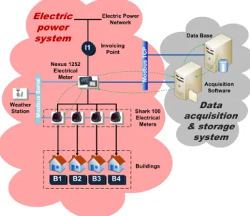
Fig. 1. Architecture of the electric system, data acquisition and storage systems.
experiment will help to improve their energy efficiency, optimize costs and reduce electric rates in the bill. This paper is organized as follows. In section 2, self-organizing maps are reviewed. In section 3, the electric power architecture, data acquisition and storage systems are presented. The experimentation methodology is ex-plained in section 4. In this section, the results of the experiment are also discussed. Finally, conclusions and further work are exposed in section 5.
2. SELF-ORGANIZING MAPS AND ELECTRIC POWER SYSTEMS
The SOM is an unsupervised neural network, based on competitive learning, that implements a nonlinear smooth mapping of a high-dimensional input space onto a low-dimensional output space. The neurons of the SOM form a topologically ordered low-dimensional lattice (usually two-dimensional) that is an outstanding visualization tool to extract knowledge about the nature of the input space data.
Each neuron of the lattice is described by ad−dimensional prototype (codebook) vector mi, in the input space, and a position gi, in the low-dimensional grid of the output space. Neurons are related to the adjacent ones according to a neighborhood functionhij, which works as a shortcut to allow lateral interactions.
The SOM algorithm implements its mapping in two stages. First, the best matching unit (BMU) of the input vector, mc, is selected by means of a competitive process c = arg minikx−mi(t)k,i= 1,2, . . . , N, wherek◦kdenotes the Euclidean norm. Then, a cooperative step is performed, where the winning unit and its neighbors are adapted:
mi(t+ 1) =mi(t) +α(t)hci(t)[x(t)−mi(t)] whereα(t) is the learning rate and the neighborhood func-tionhci(t) is usually implemented as Gaussian. The success of the mapping depends critically on the parameters of this adaptive rule, which, in general, should decrease with time.
The SOM provides a good approximation to the input space (Luttrell, 1989), similar to vector quantization (VQ), and divides the space in a finite collection of Voronoi regions. It reflects the probability density function, since regions which a high probability of occurrence are magni-fied to gather a larger quantity of neurons.
The learning rule of the map drives the neighboring units, along with the BMU, towards the current input like a flexible net folding onto the input data sets. For that reason, a spatially-ordered and topology-preserving map emerges providing a faithful representation of the important features of the input.
Some useful representations such as the component planes (Tryba et al., 1989) have been used in this work. In fact, any scalar property of the input space can be visualized in the output space using the SOM. These maps associate the property value of a certain neuron,mi, to the correspond-ing coordinates of the lattice,gi. The property values are usually shown using a color level, so the gi nodes form a picture where the property distribution for the process states is depicted.
Another way of visualization used ishit maps, also known asdata histograms(Vesanto, 1999). Such maps try to show the location of the input data on the output space. That is, if a BMU is calculated for each input sample, then a data histogram can be obtained for multiple input samples. There are several ways to visualize these maps. In this case, a 3D representation has been chosen, where the height of the bars is proportional to the number of times that a neuron of the output space is the BMU for each input sample of the whole data set.
There are many applications of neural networks in the field of electric power systems (Vankayala and Rao, 1993). Ex-amples include the assessment of the online security, fault diagnosis, load prediction, classification of consumers, etc. Some previous studies have successfully tested the use of neural networks, such us SOM, in the field of electric power systems. In (Sforna, 2000), SOM is used along with fuzzy logic to extract information from the vast amount of data stored by electricity companies in order to improve the electrical supply to its customers and offer new services according to the class of customer. SOM is also used to give information to the electricity company about the power consumption of the regular consumers. The results are contrasted with other techniques called Follow-The-Leader (Chicco et al., 2004). SOM is applied for classify-ing and identifyclassify-ing consumption patterns and the results are compared with statistical and fuzzy logic techniques (Verdu et al., 2006). In (V. Figueiredo and Gouveia, 2005), k-means algorithm is used together with SOM to char-acterize each electric consumer according to their power demand. SOM can predict the short-term consumption in the electric distribution network of a country. It is carried out using several models and submodels at different time periods and takes into account the temperature (Tafreshi and Farhadi, 2007). A prediction of consumption based on atmospheric variables is done using jointly supervised and unsupervised neural networks (M. Beccali and Marvuglia., 2004). Other authors propose an algorithm that consists of two stages based on SOM and Support Vector Regression respectively to predict peak power demand in a city (Fan
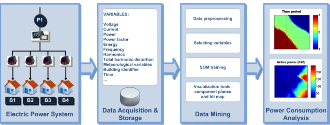
Fig. 2. Experimentation methodology.
et al., 2006). These examples are just some of the most representative works in this field.
3. ELECTRIC POWER SYSTEM AND DATA ACQUISITION
The electric system to be analyzed, along with the acqui-sition and data storage systems are shown in figure 1. It can be seen that the electric company supplies electricity to the 4 buildings from a single point on the power grid. Power and energy measurements, and therefore the billing, are performed jointly for the 4 buildings. The voltage of the supply belongs to the medium level because electric rates are cheaper for high power in medium voltage. The energy comes from the general medium voltage distri-bution network, owned by the company. A transformer (omitted for the sake of clarity) reduces the voltage to levels suitable for consumption. Subsequently, the power supply is distributed to each of the buildings as seen in the single-line diagram.
Apart from the measurement equipment installed by the electric company, other equipment whose owner is the University of Le´on was used in this study. There are two types of electric meters. The Nexus 1252 model is an analyzer/meter for large power systems and has some more advanced features than theShark 100 model which performs only basic functions of measuring and recording. The main variables measured by these meters are voltages, currents, power, power factor, energy, frequency, total harmonic distortion and harmonics. The measurements can be taken individually by each phase or an average of three phases.
In the main power line, there is a Nexus 1252 meter which measures the total consumption of 4 buildings. The secondary power lines which distribute electricity to each building has a Shark 100 meter. A serial communication network based on Modbus Serial protocol connects every
Shark 100 meters with the Nexus 1252, which works as a gateway between the serial network and the Ethernet supervision network based on Modbus TCP protocol. In addition, the Nexus 1252 meter has a I/O expansion for data acquisition. It also uses a serial network based on Modbus Serial protocol to communicate with the weather station. Therefore, this kind of meter can perform several functions simultaneously:
• To measure the electric variables from the main power line.
• To work as a gateway between Modbus Serial and Modbus TCP protocols.
• To get data from I/O modules (weather station) A software application has been developed in language C# for data acquisition and data storage. It is executed contin-uously on a separate server and sends the data to another server where there is a Microsoft SQL Server database. These two servers are connected to the supervision network based on Modbus TCP to obtain data from the meters. The software application performs requests to each meter to read data sequentially every 2 minutes, i.e. the sampling period. The aim is to get data from all variables (the total number is 85) and to store them in the structured database. For this purpose, a set of tables has been created in the database so that we can store data in a structured way.
In this process, problems could arise resulting in data loss or erroneous samples. For example an excessive traffic in the communication network or even service interruptions could happen. It will provoke packets loss, large delays in the data acquisition, etc. Furthermore, failures can appear in the acquisition and storage systems when they stop working. It generates vacant samples, i.e., no data stored in the database. Errors from meters are possible, but unusual. Generally, they just provoke outliers, values which can be easily detected and deleted. When these kind of problems happen, the acquisition system identify these samples using an error code.
4. EXPERIMENTATION METHODOLOGY AND RESULTS
4.1 Methodology
A SOM has been applied using the most representative electric variables and weather variables to visualize and an-alyze the power consumption of the whole buildings. After that, tasks or actions that minimize the associated energy and economic expenses will be applied. The methodology followed in this work is shown in figure 2. It comprises a first step for acquisition and storage of data from electric system, then a step based on Data Mining facilitates to extract information and, finally, visualization techniques are used for analyzing and making decisions.
All variables from the electric power system are stored in the database continuously thanks to the acquisition and storage systems as explained above. Stored data
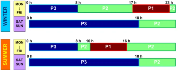
Fig. 3. Distribution of consumption in time periods ac-cording to the electricity tariff.
in the database will be the starting point for carrying out the experiment. Several functions were developed to import the variables from the database to the working environment of Matlab which is the platform where the experiment will be done.
Initially, data preprocessing algorithms are applied in or-der to detect errors, eliminate outliers, fill vacant samples and filter data. If the number of samples is very high, it is also possible to re-sample data using a lower frequency. Thus, data size will be smaller and the SOM training will consume less time and resources.
The selection of the key variables is based on problem domain knowledge as well as on the objectives pursued. Sometimes it may be necessary to calculate a new variable as a function of the existing ones in the database.
Once these tasks are carried out, the SOM algorithm is trained with the selected variables. When the training has finished, the different maps obtained from the SOM enable and facilitate the analysis and even the on-line monitoring of the electric system.
4.2 Experiment
The energy consumption (active energy, KWh and reactive energy, KVARh), together with the peak power (KW) demanded by the group of buildings are analyzed in this experiment. These three variables correspond to the terms involved in the electric bill according to the current tariff, so these variables influence in the energy cost directly. The
power term is calculated as follows:
Pf =
(0.85∗P c, ifP m <0.85∗P c
P c, if 0.85∗P c≤P m≤1.05∗P c P m+ 2∗(P m−1.05∗P c), ifP m >1.05∗P c
where P mis the maximum power value registered, P cis the power contracted and P f is the power which will be billed. In the case of theactive energy term, the measured value is applied. Finally the energy that exceed the 33% of the corresponding active energy (power factor less than 0.95) is added in thereactive energy term.
Electric company distribute the energy consumed for billing in three time periods (P1 or peak, P2 or flat, and P3 or off-peak), taking into account the hour of day, day of week and season of the year. The power demand and energy consumed in each period have a different cost. In figure 3, the distribution in time periods according to current electricity tariff is shown. In winter, P3 period corresponds to night hours (from 0 to 8), except weekends
(from 0 to 18), consumption in the middle of the day belong to P2 period (from 8 to 17 and from 23 to 0), except weekends (from 18 to 0) and P1 period includes consumption in a few hours (from 17 to 23), only normal week days. In summer, there is a small difference, P1 period groups consumption in the hours of the middle of day (from 10 to 16) and P2 period corresponds to hours from 8 to 10 and from 16 to 0. Summarizing, the electricity tariff divides power consumption into three periods:
• P3 period is the cheapest. It corresponds to the late evening and most time of the weekends.
• P2 period has a medium price. It includes to remain hours of the weekend and most of the hours of the day.
• P1 period is the most expensive. It groups very specific hours, generally peak hours.
Therefore, it is very useful to know in detail the energy consumption and power peak of the group of buildings to improve their energy efficiency, optimize the tariff and reduce costs. It also is interesting to detect relationships between consumption and the atmospheric variables to predict future behaviors.
In this experiment, 9 variables from the electric system and the weather station were used (time period, active and reactive power, power factor, active and reactive energy, temperature, humidity and solar irradiance). In this case, the first variable was added to identify the time period in which energy is consumed according to electricity tariff applied by the company. The data set used corresponds to a billing month from 18.03.2010 to 18.04.2010 with a sampling period of 2 minutes. Note that the total volume of information used is 23040 samples.
A SOM whose dimensions are 30×30 was trained using this data set. The training epochs are 50, the neighborhood function is Gaussian and the learning rate decreases ex-ponentially with time. Previously data were preprocessed to remove outliers, errors and vacant samples. A linear normalization was applied to get data in the interval [-1 1]. A weight factor was given to time period in the BMU searching process. Thus, the organization of SOM will be forced around this variable so that results will be more clear.
4.3 Results
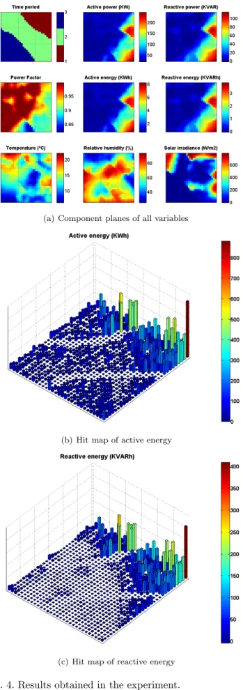
The active power component plane and the hit map for active and reactive energies were considered to visualize the three terms of the electric bill (power term, active energy term and reactive energy term). Although the hit map is unique for each input data set, the values of hits obtained were multiplied by the energy value of each corresponding neuron in the SOM and later they were summed to determine the total energy consumed. In figure 4, maps that allow us to visualize and analyze the three terms of the bill are shown.
In figure 4(a), all component planes can be seen. There are three different zones in each plane, corresponding to the three time periods in which consumption is distributed and they can be distinguished in the plane for this variable. These clusters have been produced thanks to the high weight factor given to time period component, compared
(a) Component planes of all variables
(b) Hit map of active energy
(c) Hit map of reactive energy Fig. 4. Results obtained in the experiment.
with other variables. It was 50 times higher. As expected, a strong correlation between powers and energies can be observed on component planes. The demand of power is mainly grouped around the hours of activity of the build-ings, dominating the areas with low consumption. The active power ranges between 25 KW and the peak power, 250 KW, which happens in P2 period. The power factor takes acceptable values in the three periods (greater than 0.9), except in a small zone corresponding to the period P3. It is probably due to a small power demand for weekends in the morning. If the planes of the meteorological variables are observed, it can be deduced that P3 period includes night data (low temperature, high humidity and no solar irradiance), whereas P1 and P2 periods group daytime data. This is logical according to the tariff applied by the electric company. Moreover, no clear relations can be established between temperature and consumption. Re-garding to solar irradiance, it can be seen that there is a very high consumption when solar irradiance is high, but also when it is low. This effect can be explained because there are different levels of occupation in the buildings, such as morning and afternoon activities.
In figure 4(b), the hit map for the active energy is depicted. The height of the bars represents the active energy con-sumed in the month. The distribution of time periods is visualized in a clear way. Most of the energy is consumed in a specific zones of P1 and P2 periods. In figure 4(b), the hit map for the reactive power is shown. This map is similar to the previous one, although the values of most zones are 0 because they do not exceed the threshold (33% of the active energy). Furthermore, the company normally does not bill the reactive energy in P3 period.
Analyzing carefully the hit maps of the active and reactive energy, along with the plane of the active power, it can be pointed out that the time periods with peak consumption are P1 and P2. Therefore, a favorable and economic electricity tariff in these two periods should be chosen. A reduction of consumption in these periods (a difficult task) or a divert of consumption to P3 period (when price is lower) could be tried as well.
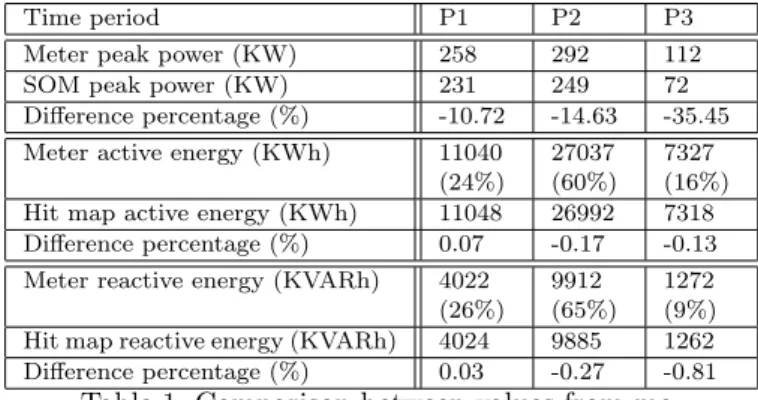
A comparison between values measured by the company and values from the SOM is proposed to validate this experiment and verify the billing. This comparison is presented in table, 1 where values for the three terms of the bill are shown and compared, indicating the differences in percentage. It can be seen that the energy values are similar, while the peak power has a significant difference. It is probably due to the smooth process produced by the SOM which deletes the occasional peak values. Thus, the energy hit maps produce a 3D visualization which summarizes the behavior of power consumption and makes an estimation close to the measured values.
Finally, every extracted information is used to make deci-sions, such as to change, modify or update the electricity tariff, negotiate the prices for each period, test and cali-brate the company meters, install equipment for correction of power factor, etc. Deviations in measurement for billing are easily detectable using hit maps and component planes. Reaching a lower price for P2 period is the great interest for these buildings since it reduces the cost of energy considerably.
Time period P1 P2 P3 Meter peak power (KW) 258 292 112 SOM peak power (KW) 231 249 72 Difference percentage (%) -10.72 -14.63 -35.45 Meter active energy (KWh) 11040
(24%)
27037 (60%)
7327 (16%) Hit map active energy (KWh) 11048 26992 7318 Difference percentage (%) 0.07 -0.17 -0.13 Meter reactive energy (KVARh) 4022
(26%) 9912 (65%)
1272 (9%) Hit map reactive energy (KVARh) 4024 9885 1262 Difference percentage (%) 0.03 -0.27 -0.81
Table 1. Comparison between values from me-ters and SOM output.
5. CONCLUSIONS AND FURTHER WORK This paper presents a method based on self-organizing maps for the extraction of information from electric power systems and the analysis of this information. In order to extract the information, acquisition and storage systems have been developed to collect electric an meteorological variables. The stored data have been used to train the SOM which reduces the dimension and visualize the data set, i.e., the data mining process.
Previous information about the electricity tariff (distri-bution time periods) has been added in order to carry out a study of power consumption from the point of view of the billing. Visualization techniques such as compo-nent planes and hit maps have been used to analyze the information. The hit map has been revealed as a very accurate technique to represent active and reactive energy consumptions.
On the contrary, the component plane of the active power does not show the peak values of the demanded power. It can be concluded that most of the consumption can be grouped in P1 and P2 periods and the peak power happens in one of these two periods for the group of buildings. The power factor usually takes acceptable values and clear conclusions cannot be obtained about the correlations between consumption and meteorological variables. The extracted information permit us to verify the electric bill. In future work, new buildings with similar features will be included in the acquisition and storage systems. It will allow us to gather lots of data to apply new data mining methods focused on the classification of buildings, discovery of consumption patterns, diagnosis and failure analysis and modeling and prediction of demanded power.
REFERENCES
G. Chicco, R. Napoli, F. Piglione, P. Postolache, M. Scu-tariu, and C. Toader. Load pattern-based classification of electricity customers. IEEE Transactions on Power Systems, 19(2):1232–1239, 2004.
S. Fan, C. Mao, and L. Chen. Electricity peak load forecasting with self-organizing map and support vector regression. IEEJ Transactions on Electrical and Elec-tronic Engineering, 1(3):330–336, 2006.
B. Forth and T. Tobin. Right power, right price. IEEE Computer Applications in Power, 15(2):22–27, 2002.
D. A. Keim. Information visualization and visual data mining. IEEE Trans. Vis. Comput. Graph., 8(1):1–8, 2002.
T. Kohonen. Self-Organization and Associative Memory. Springer, Berlin, 3rd edition, 1989.
T. Kohonen. Self-Organizing Maps. Springer-Verlag New York, Inc., Secaucus, NJ, USA, 3rd edition, 2001. ISBN 3–5406–7921–9.
T. Kourti and J. F. MacGregor. Process analysis, monitor-ing and diagnosis, usmonitor-ing multivariate projection meth-ods. Chemometrics and Intelligent Laboratory Systems, (28):3–21, May 1995.
S. P. Luttrell. Self-organisation: a derivation from first principles of a class of learning algorithms. In Inter-national Joint Conference on Neural Networks, IJCNN, volume 2, pages 495–498, 1989.
V. Lo Brano M. Beccali, M. Cellura and A. Marvuglia. Forecasting daily urban electric load profiles using arti-ficial neural networks. Energy Conversion and Manage-ment, 45(18-19):2879–2900, 2004.
M. Sforna. Data mining in a power company customer database. Electric Power Systems Research, 55(3):201– 209, 2000.
S. M. M. Tafreshi and M. Farhadi. Improved som based method for short term load forecast of iran power network. InPower Engineering Conference, IPEC 2007, pages 1377–1384, 2007.
V. Tryba, S. Metzen, and K. Goser. Designing basic integrated circuits by self-organizing feature maps. In
Neuro-Nˆımes ’89. Int. Workshop on Neural Networks and their Applications, pages 225–235, Nanterre, France, November 1989. ARC; SEE, EC2.
EIA US Energy Information Administration. Interna-tional Energy Outlook 2007 (IEO2007), 2007. URL www.eia.doe.gov/oiaf/ieo/index.html.
Z. Vale V. Figueiredo, F. Rodrigues and J.B. Gouveia. An electric energy consumer characterization framework based on data mining techniques.IEEE Transactions on power systems, 20(2):596–602, 2005.
V. S. S. Vankayala and N. D. Rao. Artificial neural networks and their applications to power systems: a bib-liographical survey.Electric Power Systems Research, 28 (1):67–79, 1993.
S.V. Verdu, M.O. Garcia, C. Senabre, A.G. Marin, and F.J.G. Franco. Classification, filtering, and identifica-tion of electrical customer load patterns through the use of self-organizing maps. IEEE Transactions on Power Systems, 21(4):1672–1682, 2006.
J. Vesanto. SOM-based data visualization methods. Intel-ligent Data Analysis, 3(2):111–126, 1999.