Data Interchange plc
Electronic Data
Interchange
Issued: 14 March 2006
Table of Contents
Electronic Data Interchange... 5
What is EDI?...5
Urgency Issues ...5
Communications ...6
The Move To Standardised EDI...6
The EDI Model...7
VDA Standard ...8
Syntax Standards ...9
Service Segments ...10
Segment Delineation Characters ...11
Streams of information ...12
Message Standards ... 12
EDI Codes and Routing ... 14
Introduction ...14
EDI Routing...14
Routing Nodes ...15
The Hierarchy of Node Types ...16
EDI codes in ODEX Enterprise ...17
EDI Codes for Clearing Centres ...17
The Makeup of an Odette/EDIFACT EDI Code ...17
The Makeup of a Tradacoms EDI Code ...18
VDA EDI Codes ...19
Encoding standards ... 19
Introduction ...19
ASCII 20 EBCDIC...21
Unicode ...21
Electronic Data Interchange
What is EDI?
For several hundred years, commerce has been based upon the movement of written documents. These documents contained the information that one company needed to convey to another company in order to do business. Over a period of time the documents started to take on standard names such as Invoice, Credit Note and Order. However, the documents were certainly not of any standard layout. They did not need to be because the recipient was always a human being and humans have the ability to read, interpret and rationalise. About all that could be said of an invoice document, for example, was that it would contain header information about the parties involved, detail lines about the products, quantities and prices, and finally some totalling information.
In the early 1950s, computers started to be used by large companies for their accounting and payroll needs. Throughout the following decades, computers rapidly took over task after task until they were involved not only in accounting, but in production, administration and all other areas of commerce. But one thing did not change. The computers still produced printed documents in various non-standard formats.
This situation was not too bad for those sending a document but was much worse for the receiver. Many documents must be sent from one company’s computer to their trading partner’s computer. Computers cannot easily read written documents, and getting them to understand what they have just read is an almost impossible task, so the receiving company would have to employ personnel to re-key the information from the received documents into the company’s computer system.
Urgency Issues
The time factor was also a problem. The company sending the document had printed it in a few seconds. It was placed in an envelope and then posted. The document would probably take several days to reach the
final destination (always with the possibility of accidental loss) where the envelope would be removed and the document presented for keying in to another computer.
For a long time, managers had been thinking how good it would be to have “Just in Time” production techniques, where a supply lorry would be able to arrive at the production line gates just in time to be unloaded and its contents taken directly to where they were needed on the production line. They dreamed of an end to costly warehousing and stock control. But these methods were impossible while the trading partners were still using the post. Lorries would be arriving at the wrong times, or not at all, causing the production lines to stop and chaos to reign, all because of the delay in the information flow.
Communications
Part of the answer to these problems was computer communications and the need to make one trading partner’s computer “talk” to another. Communications have been in existence since the early days of computers. A file can be transmitted from one computer to another, either over a normal telephone line or over a “Leased Line” that is continuously in use and dedicated to computer communications. Many commercial products exist that can move files in this way.
Communications did not solve the whole problem though. Once a file is received it needs to be understood by the receiving computer. Items of information must be in the exact place that the computer is expecting them. If just a single character is out of place, the whole file will become uninterpretable by the computer.
In the early days of communications, trading partners had to spend a great deal of time agreeing exactly where each item of information would be stored in the files that were transmitted. These agreements were only active for one trading partner. Start trading with another partner and the requirements would change slightly, a larger product code would perhaps be needed, or a different method of pricing, but the whole negotiation and agreement process had to take place all over again. It kept the programmers busy but did little for the company profits.
The Move To Standardised EDI
The solution was EDI, Electronic Data Interchange, a standard method of transferring commercial information between computers.
The Message
EDI (Electronic Data Interchange) files contain information, in one of many possible formats, pertaining to commercial documents. For example, a paper invoice will always contain certain information whatever the company or country of origin. It will contain the originating and receiving company’s information such as addresses, telephone numbers, contacts, etc. It will then have a section where the items to be
invoiced are laid out in a formatted manner, with prices and quantities, and finally it will have a totals section. All this information may be contained within an EDI file of a pre-defined format, so that whoever receives the file will be able to understand it and automatically pass this information into their own in-house systems, irrespective of the type of computer or the systems that they are running.
The Standards Bodies
A number of different standards bodies were created to define both methods of communications and the layout of standard trading documents, so that simple and cost effective electronic trading could take place. The main document standards with which we will be concerned are EDIFACT, Tradacoms and ANSI X12, but before going into detail about the standards themselves, here is a short background to the development of the UK documents standards bodies.
The earliest development of standards, usually for particular sectors of industry, was carried out in the late 1970’s under the auspices of the EAN. EAN is the International Article Numbering Organisation dealing with EDI standards. It acts as an umbrella group for the various national Numbering Organisations.
In 1998, as a result of the merger of the Article Number Association (ANA) and the Electronic Commerce Association, the e.centreUK was
launched as the EAN Numbering Organisation for the UK.
More recently, in February 2005, the e.centreUK has become GS1 UK.
This is in line with the global re-launch of EAN International as GS1.
The first UK message standards were published by the ANA in 1982, having been tested and developed since 1979. Over 90% of all UK trade EDI takes place using standards from the ANA, whose members include representatives from manufacturing, distribution, wholesaling, service and retail organisations.
The ANA standards use the two key syntaxes:
• UN/GTDI (General Trade Data Interchange), which forms the basis for TRADACOMS messages;
• UN/EDIFACT (EDI for Administration Commerce and Transport), which is the basis for EANCOM and UK EDIFACT messages. Further details about message syntax are in the sections that follow.
The EDI Model
There are three logical levels or “layers” of standards required to achieve EDI information transfer, each layer having its own controlling standards organisations (although some organisations may define more than one layer). This structured approach to EDI allows for the maximum flexibility
and also enables future developments in technology and standards to be easily incorporated.
From the lowest layer upward, these three layers are:
• The Communications Standards - Defining just how the data is to be transferred from the sender to the receiver.
• The Syntax Standards - Defining what overall standards format the EDI file will be in.
• The Message Standards - Defining exactly what the message is and what information is to be placed where within this message.
These standards are going to be further described in the following sections but it is important to remember that whatever standards are used within each layer, the layering process is required to allow flexibility. For example not all users will wish to use a specific communication protocol; some may even wish to copy the data onto a floppy disk and send it in the post! So the communications level is now a floppy disk but the higher levels still remain.
This principle of multiple methods of achieving the same goal is found over and over again within the EDI regime. It is not an attempt at duplication but is designed to give users the best possible solution and flexibility in all cases.
The Communications Standards are described in a section of their own.
VDA Standard
It should be noted that VDA messages are treated as non-EDI files by most members of the ODEX family. This is because VDA messages are not true EDI messages.
VDA stands for Verband der Automobilindustrie (Motor Industry Association). The VDA is a German automotive standards body which issues the VDA standard documents. VDA messages are not strictly EDI messages as they are simply flat files. Instead of using special characters to divide each segment from the next and each data element from the next, a VDA message consists of fixed length records within which each data element (field) is allowed to take up a specific number of characters. If any item of data is omitted, its absence must be shown by a space the same length as the omitted item of data.
Furthermore, VDA messages do not contain service segments, so there is no concept of interchange or group. However, the first record in a VDA message does contain addressing information of a kind and can therefore be used by an intelligent program such as ODEX Enterprise or DARWIN for routing purposes.
There are enough similarities between VDA messages and true EDI messages to allow VDA messages to be treated by some programs as EDI. VDA messages have a hierarchical structure, meaning that records within a message must adhere to certain rules about the position in which they may appear. VDA records, like EDI segments, also have attributes such as a name, a maximum number of times they may occur and whether their occurrence is mandatory or conditional.
Owing to the differences that exist between the VDA standard and real EDI standards, VDA messages are usually treated as non-EDI files. However, ODEX Enterprise and DARWIN 3 have been programmed to recognise VDA messages and to treat them as if they were real EDI messages.
Syntax Standards
The middle level in our three layer EDI model is the Syntax Standard to be used. Taking the analogy of a telephone call, it is no use if the call is connected but the remote party does not speak the same language as the caller; a few minutes will be lost whilst each side tries to understand the other but no meaningful information may be exchanged.
To avoid this problem, three main syntax standards are used for EDI. These are the American ANSI X12 standard, the European EDIFACT standard and an older European standard still very popular in some sectors such as the retail industry, UNGTDI (United Nations Guidelines for Trade Data Interchange). There is also the VDA syntax standard, used in Germany. Although not strictly EDI, VDA messages have been included under the EDI umbrella.
With the exception of VDA, no matter what standard is used, the same EDI terms and concepts apply. Let us now look at these terms and what they mean in more detail.
An EDI “Message” may be split up into a number of logical units. The message is itself a single document such as an invoice or an order, and is made up of a number of “Segments”. Each segment contains complete information about a part of the document. For example two segments that will be required in an invoice message are the buyer’s and seller’s details. Segments can themselves be split down into “Data Elements”. Data elements hold the actual information. Simple data elements hold only one item of information, such as a name or a value. Composite data elements hold one or more “Sub-Elements” of closely associated information such as the lines of an address.
EDI messages between two trading partners may be grouped together into an “interchange”. The interchange may contain messages of varying types, the only common factor being the sending and receiving parties. All EDI files must contain at least one interchange; this ensures that the interchange can be routed to the correct destination.
Messages of the same type can be held together in a “group”. The functional group is not a very widely used vehicle, most partners considering that as the interchange is the main routing method and may contain many messages, then the group is somewhat superfluous. Different standards call the group different names. The group itself is an EDIFACT term, UNGTDI standards know it as a “batch” and ANSI X12 standards as a “document”. ANSI X12 also calls the message a “transaction”.
Service Segments
Interchanges, groups and messages are identified in an EDI file by special segments known as service segments. Service segments contain the information necessary to route the interchange towards its final destination, to identify the contents of the interchange, its date and time of production, standards used and much more. Remember that the interchange may be passing through several different routing agencies, just as a letter is passed to and through the post office before reaching its final destination. EDI is not always a point-to-point matter. The service
segments act in the same way as the envelope and enclosed document headings used in paper correspondence.
Service segments enclose a block of segments that they are defining. In other words there will be service segments both at the start and end of each interchange, group and message. The service segment’s names are different for each syntax standard. The following is a list of service segment types and their equivalents for each of the common standards.
UNGTDI EDIFACT ANSI X. 12 Start of
Interchange
STX UNB ISA
Start of Group BAT UNG GS
Start of
Message MHD UNH ST
End of Message
MTR UNT SE
End of Group EOB UNE GE
End of Interchange
END UNZ IEA
Segment Delineation Characters
Obviously some method is needed to indicate the end of one segment and the start of the next, and likewise for the end of one data element and the start of the next. The manner of achieving this is by segment delineation characters. These characters are used to split the EDI file up into its constituent parts. Each syntax has its own default delimiters, i.e. those that are used if no others are specified, but in most cases these can be overridden by special means if necessary.
The default segment delineation characters that are used for the main three EDI syntaxes that we are considering are given in the following table.
UNGTDI EDIFACT ANSI X12
End of Segment ‘ ‘ FS (X’1C) or + End of Element + + GS (X’1D) or * End of Sub-Element : : US (X’1F) Control Character Escape ? ?
Streams of information
The use of service segments not only allows routing of EDI data between trading partners but also allows the concept of regular data “streams” to be implemented, allowing the trapping of missing data and regular activities to be performed on EDI interchanges.
Interchanges from each trading partner may be identified by the contents of the interchange control segment. A sequence number in the segment allows the receiver to check that this interchange is greater than the last one, avoiding possible duplication, and also allows for missing sequences and hence missing interchanges to be identified.
In real life these cases may be more complex. Routing via a VAN may cause some interchanges to be received out of sequence. This scenario would be similar to the post arriving at your premises. The post is dumped in an unsequenced pile in the mailbox and the letters are then opened in any sequence. There is no guarantee that the sequence of documents processed or “opened” is correct.
To solve this problem the concept of a sequence “window” is used. So long as the increase in the application reference number is not greater than the window size, then all is well and the sequence may then be checked for missing numbers at a later time when all the documents are expected to have been received.
Message Standards
In our telephone analogy, our telephone callers may exchange information because both parties are speaking the same language and understand the protocols that they must use, but unfortunately the remote party still does not understand the information that the caller is giving because they are from different industries and each industry has its own jargon and sequence or layout of information. To get over this problem the final layer of the EDI model was developed, in which both trade-specific and general document standards are defined by the controlling organisations.
It should be mentioned at the outset that the message standards are subject to different interpretations and even misuse by some trading partners, so it is vital to get agreements between partners not only about the message standards used but also about the exact meaning and contents of information, before EDI interchanges are exchanged. Many large organisations publish their own implementation manuals for the standards that they wish to use. Even though these standards are based upon an industry standard message, there may well be minor differences in layout and format.
The EDIFACT message standard is the most widely used in Europe. EDIFACT is a general-use standard not linked to any particular industry and is controlled by the EDIFACT board closely associated with both the
EAN numbering associations and the United Nations. For the automotive industry there is ODETTE (Organisation for Data Exchange by Tele-Transmission in Europe) and VDA (Verband der Automobilindustrie). ODETTE have historically had their own standards but have, since 2000, adopted the EDIFACT standards. The VDA standard is not a true EDI standard but does have many similarities. Many other industry specific organisations exist, such as CEFIC for the chemical industry and TRADACOM for the retail industry.
So what is a message standard? From the introductory section you will have learned about the need to code a paper document’s information into electronic form. In the previous sections we have looked at ways of moving data electronically and ways of getting a computer to understand the format (syntax) of a file by splitting it up into messages, segments and data elements. Now all that is left is to define exactly what item of information is going to be contained in which segment, element, etc. That is the purpose of the message standards.
Each message standard is firstly defined by a structure diagram detailing the segments and where they occur. Each segment on the structure diagram is defined as having a number of attributes. These are a name, a maximum number of occurrences and a mandatory or conditional status. The segment is drawn on the diagram as shown below.
Here we see a NAD segment (NAD segments are used by EDIFACT to define Names and Addresses) where the segment name is held in the top section of the diagram. The segment is Mandatory ( M ) meaning that it must occur at least once in the message. The alternative to mandatory is Conditional ( C ) meaning that it need not occur if there is no information to be held in it. The segment is repeating ( R ) which means that it may occur more than once. An invoice, for example, may have more than one item line on it. Alternatives to this are the number 1 for a segment that may only occur once, or a number defining the maximum number of times that the segment may occur.
Message Structure
Many of these segment diagrams are combined together to form a message structure diagram. The message structure is hierarchic, meaning that segments may appear at a number of different levels and some segments will act as “parents” and “children” to others to define more complex pieces of information. To take a simple example, an item of goods appearing on a document, an invoice or order perhaps, would have a basic description held in a parent segment and then be further defined by child segments under the parent which describe its
dimensions, its cost, its markings and many other attributes. These child segments may themselves be parents to more detailed segments, for example the segment holding the price may have date information segments under it as the price changes with time.
EDI Codes and Routing
Introduction
An EDI Code is analogous to an address found on the envelope of a letter and forms the basis for all EDI routing. In this section we look at the use of EDI codes.
There are two basic types of EDI code: physical codes and logical codes. A physical EDI code pertains to a physical computer or EDI system. A logical EDI Code could be:
• a computer application such as an invoicing system
• a trading sub division of a company, for instance a manufacturing plant
• a company (in legal terms)
• a corporation (a collection of companies)
EDI Routing
EDI routing, the path which guides the EDI data to its final destination, may be a long and winding trail. Organisations themselves are often complex and a large multinational organisation may hide a world-wide network with many computers and systems. Files entering through a corporate gateway (a single access point from the corporation to the outside world) must be onward routed by that organisation to their final destination.
There are three levels at which EDI data is routed through such a system.
• Physical routing (in OFTP terms called SSID routing). This is routing during a communications connection by physically contacting another system using a network such as the X.25 packet switching system. The EDI code at this level is referred to as the SSID code.
• File routing (in OFTP terms called SFID routing). The largest collection of data crossing a physical connection will always be a file. A file may contain many EDI interchanges but will still always be considered as a single file. The EDI code at this level is referred to as the SFID code.
• Interchange routing (sometimes called UNB, STX or ISA routing). Examination of the contents of an EDI file will enable the forwarder to split a single file into one or more EDI interchanges, all of which will
contain interchange control segments with origin and destination EDI codes. The EDI code at this level is referred to as the EDI code.
The first of these three routing methods handles the physical routing and the latter two methods handle logical routing.
Routing Nodes
The entities which exist at the three levels of routing are sometimes called nodes. The three basic node types are:
• Network Node (sometimes called the Physical Node or SSID Node)
• File Node (sometimes called the SFID Node)
• Message Node (sometimes called the UNB Node).
The last two node types, File and Message Nodes, are also called Logical Nodes. The Message Node is not strictly part of OFTP addressing.
Each Network node may have one or more File nodes and each File node may have one or more Message nodes.
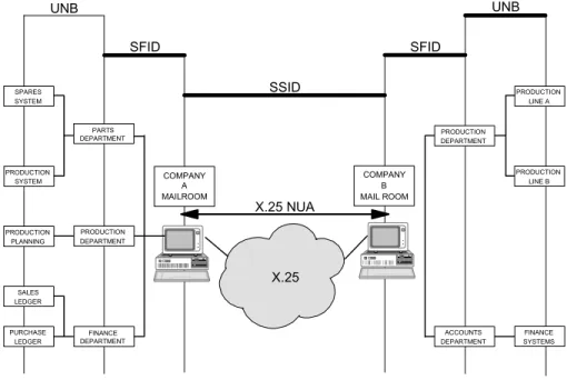
UNB SFID SFID UNB SSID X.25 NUA X.25 COMPANY A MAILROOM COMPANY B MAIL ROOM SPARES SYSTEM PRODUCTION SYSTEM PRODUCTION PLANNING SALES LEDGER PURCHASE LEDGER PARTS DEPARTMENT FINANCE DEPARTMENT ACCOUNTS DEPARTMENT PRODUCTION LINE A PRODUCTION LINE B FINANCE SYSTEMS PRODUCTION DEPARTMENT PRODUCTION DEPARTMENT
Figure 1 - Illustration of EDI routing
A simple analogy for EDI routing nodes (origin or destination points of contact) is to consider the structure of a medium to large company. Incoming mail for that company will be delivered to the mailroom. The mailroom is therefore the equivalent of the network node as it is the point of contact with the outside world.
The mail will then be sorted and delivered to each department in bundles. The department is the equivalent of the file node.
Finally each letter will be delivered to an employee, or section, within that department. This is the equivalent of the message node and the information has reached its final destination.
In smaller companies some of these sections will be omitted so that the mailroom, the department and the final destination are all the same person. So it may be with EDI. In this case all three levels will share the same EDI code.
The Hierarchy of Node Types
To further understand the reason for these different types of node and hence the attributes of each node, it is necessary to look at the communications aspect of an EDI file.
The Session Level
Let us assume that an EDI file has been scheduled to be sent to the Accounts Department’s Sales Ledger section of company A. A communications session is started with company A. The first contact and first level of validation that this data is being sent to the correct place is when the trading partners identify each other and exchange passwords. This level of communication is carried out at Network Node level. In the OFTP protocol, the SSID (Start Session Identity) is used to exchange this information and agree certain standards between the partners.
The File Level
Once the session has been started and passwords have been exchanged, the file may be sent. High level information is exchanged and again there has to be agreement between the two partners that, for example, the receiving partner has an Accounts Department (the destination of the file) and enough room on his system for the file to be sent. In the OFTP protocol, the SFID (Start File Identity) is used to exchange this information.
The Message Level
Finally the EDI data itself may now be transferred between the partners. The EDI data contains its own internal addressing. In the UNB segment (for EDIFACT), the STX segment (for UNGTDI) or ISA segment (for ANSI X12), there must be routing information defining both the sender’s and receiver’s EDI Codes. In this case the EDI code of the Sales Ledger section will be defined in the message as the receiver of this data.
In practice, many users, particularly smaller companies, do not wish to use all three levels of routing. These users will have only one EDI code defining all three levels. ODEX can cater for these users and trading
partners as well by allowing all three levels to be defined in a single user profiling operation, creating a combined Network Node, File Node and Message Node with the same EDI Code.
EDI codes in ODEX Enterprise
In ODEX Enterprise, the terms Network Node, File Node and Message Node are not used, and the hierarchical nature of the nodes is not so obvious as in other ODEX members, but the EDI codes for each level are still required.
The SSID is defined on the Overview page, the SFID is defined on the Mailboxes page and the EDI code is defined on the EDI Codes page. Just as in other ODEX members, all three EDI codes can be defined at once, from the Overview page, if they are identical at all three levels.
EDI Codes for Clearing Centres
When communication between two trading partners is achieved via one or more clearing centres, such as DINET, the SSID code of the user’s clearing centre must be used as the Network Node (SSID) in ODEX or DARWIN 3, while the SFID and EDI code of the user’s trading partner must be used for the File Node (SFID) and Message Node (EDI code).
The Makeup of an Odette/EDIFACT EDI Code
Network and File Node EDI codes may be up to 25 characters long but at interchange level an EDI code may be as many as 35 characters. The codes should be made up using the following list of characters and no others.
A to Z Uppercase alphabetic characters 0 to 9 Numeric characters - Hyphen / Slash or Oblique , Comma . Full Stop & Ampersand ( Left hand bracket
) Right hand Bracket
Blank or space (CAUTION - this is NOT recommended as some systems cannot cater for it).
There are currently no standards for EDI codification schemes. Obviously it is vital that the code should be unique. New EDI users have a number of choices available to them:
• Choose their company name (not recommended)
• Be allocated an EDI code by a third party network (VAN) or trading partner
• Derive their own EDI Code
If users wish to take the latter course of action, the following are the Odette recommendations for the structure of an EDI code.
Length Name Description 1 Code Prefix The letter ‘O’
4 ICD Code The ICD (International Code Designator) is a 4 character code as specified by the ISO standard ISO 6523. This identifies a standards organisation responsible for managing a numbering scheme. The scheme could either be an international scheme, such as the European Article Numbering Association (EAN) or a national scheme such as the U.K. Company Registration number.
14 Company Code
This is the code assigned by the agency specified in the ICD code above. If it is less than 14 character positions, then it should be right aligned and zero padded to the left.
6
Sub-Address This alpha-numeric field is a user assigned sub-address. It can identify various Physical Addresses within an organisation.
An example EDI code for Data Interchange Plc would be :- O093200000002078041SYS001
O is the code prefix
0932 is the ICD for the U.K. company registration scheme
2078041 is the Company Registration number for Data Interchange Plc.
SYS001 is a locally assigned code to describe the EDI entity.
Please note that this is a recommendation for the formation of an EDI code and NOT a standard.
The Makeup of a Tradacoms EDI Code
Network and File Node EDI codes may be up to 25 characters long but at interchange level a Tradacoms EDI code must be no more and no less
than 13 numeric characters long. In the Tradacoms standard, EDI codes are referred to as ANA codes and may be obtained from one of the standards bodies, such as DUNS or GS1.
If users prefer not to use the standards bodies, the following are the Data Interchange recommendations for the structure of a Tradacoms EDI code.
Length Name Description
4 ICD Code The ICD (International Code Designator) is a 4 character code as specified by the ISO standard ISO 6523. This identifies a standards organisation responsible for managing a numbering scheme. The scheme could either be an international scheme, such as the European Article Numbering Association (EAN) or a national scheme such as the U.K. Company Registration number.
9 Company
Code This is the code assigned by the agency specified in the ICD code above. If it is less than 9 character positions, then it should be right aligned and zero padded to the left.
An example Tradacoms EDI code for Data Interchange Plc would be :- 0932002078041
0932 is the ICD for the U.K. company registration scheme
2078041 is the Company Registration number for Data Interchange Plc.
Please note that this is a recommendation for the formation of an EDI code and NOT a standard.
VDA EDI Codes
Network and File Node EDI codes may be up to 25 characters long but at interchange level an EDI code can only be a maximum of 9 characters.
For VDA communications, users are normally allocated an EDI code by their trading partner. This EDI code is usually their supplier code. Trading partner EDI codes are usually their customer code.
Encoding standards
Introduction
Encoding standards deal with the representation of data within the computer. All computers store data in binary format, but the same
character can be stored differently depending on the encoding standard used.
Some encoding standards, such as ASCII and EBCDIC, are based on an 8-bit byte (or octet), which allows them to represent English letters and some non-English characters, graphics symbols, and mathematical symbols. Some ASCII standards are only based on 7-bit bytes.
Other encoding standards, such as Unicode, are based on two octets (16 bits), allowing them to represent a much larger character set including Arabic, Cyrillic, Greek and Hebrew characters as well as English.
To illustrate how various encoding standards represent the same character differently, we can use the letter A as an example, showing its binary bit pattern.
• in ASCII format, A is represented by 01000001
• in EBCDIC format, A is represented by 11000001
• in Unicode format, A is represented by 0000000001000001
This means that, for example, if a file in EBCDIC format is transferred to a computer which expects files in ASCII format, each character will be interpreted as if it were in ASCII, in effect becoming corrupt and losing its meaning.
One answer is to allow for the conversion of files from one format to the other when transferred between computers which use incompatible encoding standards. ODEX Enterprise, for example, recognises EBCDIC files and can convert them before displaying their details in human-readable text. However, if a user tries to view an EBCDIC file using a standard editor, such as Notepad, no conversion will be done and the file will be illegible.
N.B. All the encoding standards represent characters as numbers so that they can be stored as binary values. This means that the binary bit pattern which represents each character also represents a number. For example, the binary bit patterns for the letter A, shown above, also represent the numbers 65, 193 and 65 respectively. To the computer, the character is no different from the number. The difference is only made by the programs which access the data and must define the data as numeric or non-numeric.
ASCII
ASCII (prononunced “ask-ee”) stands for American Standard Code for Information Exchange.
ASCII is a code for representing characters as numbers inside the computer. The standard ASCII character set uses just 7 bits for each character, which allows each letter to be assigned a number from 0 to 127. For example, the ASCII code for uppercase A is 65.
There are several larger ASCII character sets that use 8 bits, which gives them 128 additional characters. The extra characters are used to represent non-English characters, graphics symbols, and mathematical symbols.
ASCII encoding is used by all PCs, Unix machines and Apple Macs.
EBCDIC
EBCDIC (pronounced “eb-sih-dik”) stands for Extended Binary-Coded Decimal Interchange Code. EBCDIC is an IBM code for representing characters as numbers inside the computer and is based on an 8-bit byte.
EBCDIC was developed at a time when one of the main criteria for the character set was its ease of use with punched cards. Even though the days of punched cards are long gone, EBCDIC is still used in IBM mainframes, such as MVS, and mid-range systems, such as the AS/400, mainly for backward compatibility.
Unicode
True Unicode, based on 16-bit character representation, provides a single unique number for every character, no matter which platform, language or program is being used. This means that if all systems were to adopt Unicode as their encoding standard, there would be no need for conversion. However, most systems have continued to use ASCII or EBCDIC, and Unicode is as yet mainly used by systems where a different language character set is required, such as Chinese or Arabic. As well as true Unicode based on 16 bits (2 bytes or octets), Unicode has several other versions, such as UTF7 and UTF8, which are simply Unicode versions based on 7-bit and 8-bit encoding respectively.
All Unicode is based on the ASCII representation of characters. In some systems, when the characters are part of the ASCII character set, the character representation is held in the second byte while the first byte represents binary zero. This is called Little Endian Unicode (i.e. the bytes in each file character are low order first). In other systems, the representation is vice versa. This is called Big Endian Unicode (i.e. the bytes in each file character are high order first).
Files encoded in Unicode, Big Endian Unicode and UTF8 all contain a byte order mark in the first few bytes of the file to indicate how the file is encoded.
Big and Little Endian encoding is only applicable to encodings which use 2 bytes per character (i.e. true Unicode). On a Windows system, most applications will expect Little Endian encoding. Mainframes will expect Big Endian encoding. Unix systems may use either, depending on their operating system.
Whether a system uses Big or Little Endian encoding is inherent in that computer system. Even if character representation is only based on 8 bits, the system is still referred to as either Big Endian or Little Endian.
File encoding in DI products
DARWIN 3 and all members of the ODEX family support the use of both ASCII and EBCDIC encoding. ODEX Enterprise supports not only ASCII and EBCDIC but also Unicode and its variations. Uniquely, ODEX Enterprise can recognise which encoding it is dealing with.
In the case of DARWIN, messages received from specific trading partners (i.e. those, such as Ford, whose data is produced on mainframes) are expected in EBCDIC format and are therefore translated into ASCII on receipt. Messages for these trading partners are translated into EBCDIC before they are sent.
ODEX/MVS and ODEX/400 are both based on EBCDIC. All other ODEX members are based on ASCII.
In the case of all ODEX members apart from ODEX Enterprise, the user must configure the details for each trading partner to specify whether files to and from the trading partner are to be translated from and into EBCDIC. In the unlikely event that a trading partner normally using EBCDIC were to send a file in ASCII format, ODEX would in fact try to translate the ASCII file into ASCII, resulting in an unintelligible file.
ODEX Enterprise, however, can recognise the encoding of files sent in any of the following formats:
ASCII, Big Endian Unicode, EBCDIC, Unicode, UTF7, UTF8
Using the Workflow Manager, ODEX can be configured to translate files in any of these formats into another of these formats before passing the file on to a system requiring the translated file.