Voltage and Frequency Controller for An
Autonomous Asynchronous Generator
Ambarnath Banerji1, Sujit K. Biswas2, and Bhim Singh3
1Dept. of Electrical Engg. Meghnad Saha Institute, Technology, Kolkata, India 2Dept. of Electrical Engg. Jadavpur University Kolkata, India 3Dept. of Electrical Engg. Indian Institute
of Technology, Kolkata, India
[email protected], [email protected], [email protected] Abstract: A battery Energy storage system (BESS) based voltage and frequency controller (VFC), for an Autonomous Asynchronous Generator (ASG) driven by an uncontrolled pico hydro turbine used in constant power mode, is presented in this paper. Excitation of the asynchronous generator with capacitor bank enables it to generate rated voltage at no load. The additional reactive power demand of the ASG on load and that for the load itself is provided by the VFC. The proposed controller has the capability of harmonic reduction, load balancing and load leveling along with voltage and frequency control. The VFC has been realized using an IGBT based current controlled voltage source converter (CC-VSC) having a battery at its DC link. A simple and effective linear control scheme using SPWM control has been used to control the CC-VSC. This control scheme is easier to implement on hardware than the other reported schemes, as it involves only linear PI controllers. The effectiveness of the proposed controller for an autonomous generator is demonstrated by simulation on MATLAB platform.
Keywords: Autonomous Asynchronous Generator(ASG) , Voltage and Frequency Controller(VFC), SPWM control, Linear and nonlinear loads, Battery energy storage system (BESS).
I. Introduction:
The rapid depletion fossil fuel and changes in world economic environment causing the increase of the fuel cost have given thrust to research on alternative and nonconventional sources of energy. Some of the nonconventional sources of energy like micro or pico hydro generation and wind power are available at remote location and of small capacity. This called for a generator which is easy to install, cost less, easy to maintain, rugged and reliable. One generator which met all of the requirements is the induction generator [1]. Further deregulation of power system has allowed autonomous generation of electrical energy [2]-[3]. Thus autonomous asynchronous generator (AAG) with its excitation requirement being met by a capacitor bank connected across its terminals [4]-[8], has become the most suitable option. However the major hurdle in its commercialization is the poor voltage and frequency regulation. This has led to a number of attempts to investigate the voltage and frequency controllers for constant [9]–[16], as well as variable power applications [17]-[19]. The reported controllers support either three phase 3-wire or three phase 4-wire systems. The later catering for single phase loads also.
Most of the reported attempts for voltage and frequency controller for autonomous generation with induction generator are based on hysteresis control or carrier less control. In this paper an attempt has been made to achieve features similar to the above control with carrier based control or SPWM control. Such a control is inherently linear and uses PI or PID controls, which are very easy to implement in real time and are less complex in hardware than the above control. A constant power input like a Pico-hydro turbine is considered for providing input to the asynchronous generator.
2. System Configuration
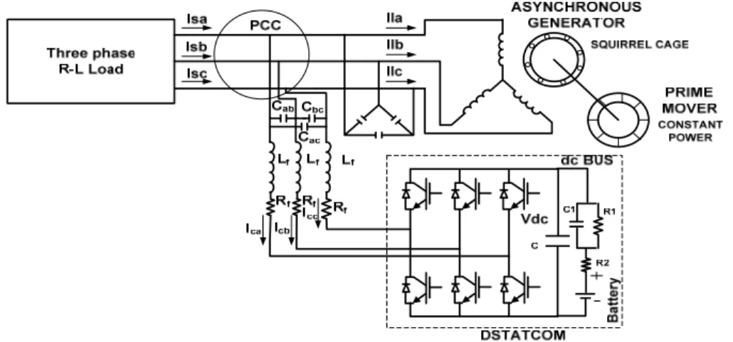
Figure 1 shows the schematic configuration of the autonomous power system being considered. A squirrel cage induction motor is operated as an asynchronous generator by a Pico-hydro turbine with constant input power. The no load excitation is provided by a delta connected capacitor bank. Consumer load both in the form linear and nonlinear loads are connected to the autonomous asynchronous generator. A battery energy storage system (BESS) based voltage and frequency controller (VFC) is connected at the point of common coupling (PCC).
Figure 1. Schematic diagram of the autonomous power system.
When the consumer load is connected, the additional reactive power requirement of the asynchronous generator to maintain the terminal voltage is provided by the VFC. The VFC also does load leveling i.e. maintains the load on the asynchronous generator constant. If the consumer load reduces the VFC charges the battery and maintain the load on the generator constant. As the input power provided by the turbine is constant, the frequency of the system remains constant. The VFC also provides harmonic elimination and load balancing at the PCC. Any unbalance in the load either caused by single phase load or by the unbalance in the three phase load is balanced by the VFC at the PCC and is not allowed to disturb the other consumers. Thus the power quality of the consumer load is greatly enhanced.
The heart of the VFC is a three legged current controlled voltage sourced converter (CC-VSC) with a battery connected to its dc bus. The CC_VSC is connected to the PCC through inductors and resistors Lf and Rf, which can be the per phase leakage inductance and resistance of the coupling transformer. The operation of the CC-VSC is controlled by SPWM controller. 3. Sinusoidal PWM Control
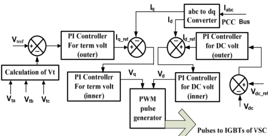
The schematic diagram of the Sinusoidal PWM controller is shown in Figure2. A high frequency carrier based sinusoidal PWM is used for generating the switching pulses for the IGBTs of the VSC [20]-[23]. This algorithm is based on the instantaneous reactive power theory. The instantaneous voltage and current of the supply system and the load are measured. The three phase system is transformed to a synchronously rotating reference frame using Park’s transformation [24] [25]. The compensation is achieved by control of id and iq.
The instantaneous id reference current is generated by PI regulation of the dc terminal voltage with respect to a reference dc voltage. Similarly iq reference current is generated by PI regulation of the ac terminal voltage of the VSC with respect to a reference ac terminal voltage [22][23]. The decoupled id and iq components obtained from abc to dq transformation of the measured instantaneous three phase current, are then regulated with two separate PI regulators with respect to the reference id and iq currents obtained earlier. In order to synchronize the abc to dq0 transformation a Phase Locked Loop (PLL) is used.
Figure 2. Schematic diagram for Sinusoidal PWM control 4. Algorithm for Modelling of Carrier Based Control of DSTATCOM
The control of VSC shown in Figure2, is modeled in discrete mode using ode23tb on MATLAB platform [26]. The discrete-time integrator block [27] is used to implement the PI controller. Forward Euler method is used for integration. The discrete-time integrator block approximates 1/s by T/(Z-1), which results in the following expression for the output Y(n) at the nth step .
Y(n) = Y(n-1) + KT* U(n-1) (1)
Where U(n-1) is the input to the controller at the (n-1)th step. T is the discretization time interval.
(1) PCC terminal Voltage Control
The three phase supply voltage (vsa vsb and vsc ) are considered sinusoidal and hence their amplitude is computed as:
Vt = √ {(2/ 3) (v2sa + v2sb + v2sc )} (2)
The Vt computed above is compared with the desired terminal voltage Vtref . The ac voltage error Ver(n) at the nth sampling instant is
Ver(n) = (Vtref - Vt(n)) (3)
Where Vt(n) is the amplitude of the sensed three phase ac voltage at the PCC terminal at the
nth instant. The error Ver(n) is fed to an outer PI controller, using discrete time integration, to
generate the Iqref .
Iqref (n) = Iqref (n-1) + K a p {Ver(n) - Ver(n-1) } + Kai Ver(n) (4) Where K ap and Kai are the proportional and integral gain constants of the outer PI controller of the ac terminal voltage at the PCC
The actual Iq is generated by an ‘abc to dq convertor using parks transformation over the load current. The Iqref and Iq are compared and the error is fed to an inner PI current controller to generate Vq .
Iqer(n) = (Iqref (n) - Iq(n)) (5) Vq(n) = Vq(n-1) + Kbp {Iqer(n) - Iqer(n-1)} + Kbi Iqer(n) (6) Where Kbp and Kbi are the proportional and integral gain constants of the inner PI controller of the ac terminal voltage at the PCC
(2) Control of the Voltage at the dc terminal of the VFC
The dc voltage error Vder(n) at the nth sampling instant is computed by comparing the Vdc of the dc bus with the desired dc bus voltage Vdc_ref .
Vdcer(n) = (Vdc_ref - Vdc(n)) (7) Where Vdc(n) is the sensed dc voltage at the dc bus of the VFC at the nth instant.
An outer PI controller uses the dc voltage error Vder(n) to generate the Idref .
Idref (n) = Idref (n-1) + K a p {Vdcer(n) - Vdcer(n-1) } + Kai Vdcer(n) (8) Where K ap and Kai are the proportional and integral gain constants of the outer PI controller of the dc bus voltage.
The actual Id is generated by an ‘abc to dq convertor using parks transformation over the load current. The Idref and Id are compared and the error is fed to an inner PI current controller to generate Vd
Ider(n) = (Idref (n) - Id(n)) (9)
Vd(n) = Vd(n-1) + Kbp {Ider(n) - Ider(n-1)} + Kbi Ider(n) (10) Where K bp and Kbi are the proportional and integral gain constants of the inner PI controller of the dc bus voltage.
(3) PWM current Controller
The Vd and Vq signals generated above are converted into modulation index ‘m’ and phase ‘Ф’ which are then used by the PWM modulator for producing the required pulses for firing the IGBTs of the VSC. This causes the VSC to maintain the terminal voltage of the generator by generating / absorbing the required reactive current and supplying / absorbing active power from the generator to charge the battery and maintain the dc side voltage of the converter. 5. Design of BESS
The battery has been modeled by its Thevenin equivalent circuit [28 ] [31 ] and has been represented as such in Fig.1 & 2. Vdc is the dc bus voltage, Voc is the no load open circuit voltage of the battery, R2 is the internal resistance and the over voltage condition is represented by the parallel combination of R1 and C1. The resistance R2 is usually small. Since the self discharging current of a battery is small, the value of R2 is large. The terminal voltage of the battery [ 32] is given by m V Vb rms 3 2 2 ) ( = (11)
‘m’ is the modulation index, with a maximum value of 1. Vrms is the line voltage on the ac side of VSC.
Energy stored in the battery is measured in kWh. The equivalent capacitance of the battery model can mathematically represented by [28 ] [33]
) ( . / ) * * ( 3 2max 2min 1 kWh 3600 10 05Voc Voc C = − (12) Vocmax and Vocmin are the maximum and the minimum open circuit voltage of the battery during its operation. From the above equations, different parameters of the battery are selected and are given in the Appendix.
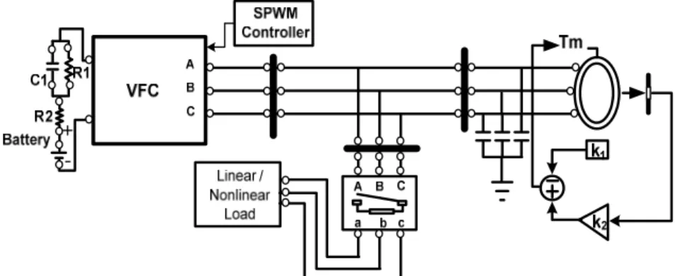
Figure 3 shows the MATLAB based simulation model of the AAG along with its controller. A 4kW, 415V, 50Hz, 4-pole, Y-connected asynchronous machine is used for autonomous operation. Data for characteristics of the machines are obtained simulation of saturation and are given in the Appendix and are used in the model. The simulation is performed on MATLAB platform (version 7.1) in discrete mode at 5 µsec step size with ode 23tb (stiff/TR-BDF-2) solver.
Figure 3. MATLAB based simulation model of an autonomous asynchronous generator with BESS based voltage and frequency controller.
6. Results and Discussions:
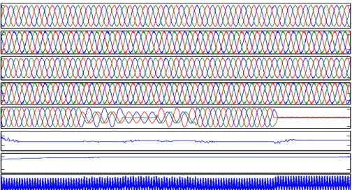
The performance of the proposed controller for an autonomous asynchronous generator is observed when subjected to balanced/ unbalanced linear and nonlinear loads. Simulated and transient waveforms of the generator voltage (Vabc_B4), generator currents (Iabc_B4), consumer load current (Iabc_B3), controller current (Iabc_B2), controller bus voltage (Vabc_B2), battery voltage (Vdc), Battery current (Idc), speed of asynchronous generator (w), and total harmonic distortion at the PCC (THD Va_B4) at different dynamic conditions are shown in Figure4 and Figure5 for linear and non linear loads respectively. The simulation demonstrates the voltage and frequency control aspect, load balancing and load leveling aspect and the harmonic elimination aspect of the VFC. Parameters of the asynchronous generator considered, is presented in Appendix. Figure6 and Figure7 demonstrate the harmonic spectrum of source voltage and current with balanced / unbalanced linear and non linear loads.
A. Performance of AAG with BESS based VFC Feeding linear load
Figure 4 demonstrates the performance of the BESS based VF controller for an AAG with balanced / unbalanced R-L loads. The system starts with a static load of 1kW on generator bus and no load on consumer bus. Load is applied on the consumer load bus at 0.5 sec. However the generator bus current remains constant. The increased load is supplied by the controller, represented by increased battery current Idc. This demonstrates the load leveling aspect of the VFC. The consumer load is 1kW and 200 VAr per phase, i.e. a total 3 phase load of 3kW and 600 VAr.
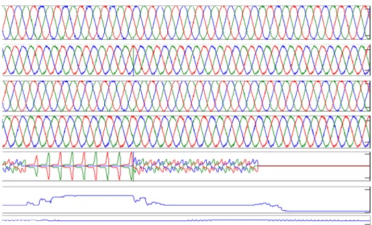
Figure 4 Performance of the VFC for an AAG with balanced / unbalanced Linear loads.
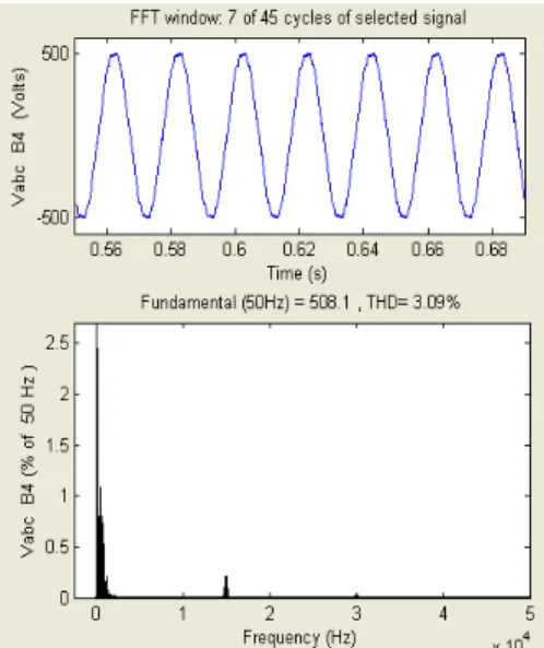
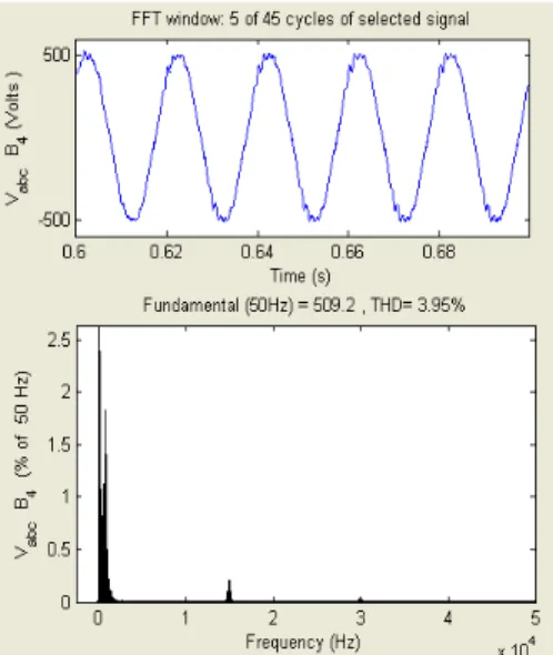
Figure 5a. Harmonic spectrum of AAG source voltage with balanced linear Load. The consumer load is delta connected. At 0.55 sec one phase is opened and at 0.6 sec another phase is opened creating an unbalanced load. Again the phases are reconnected at 0.65 sec and 0.7 sec making the load again balanced. The VFC maintains the generator voltage and current constant, which shows the load balancing aspect of the BESS based VF controller. Load is removed from the consumer load bus at 0.8 sec. After removal of the consumer load at 0.8 sec the battery again starts charging with generated power of AAG. This demonstrates that the BESS based VF controller maintains the load on the generator bus constant and thus it is able to regulate the generator speed and hence the system frequency constant. During the entire simulation the speed (w) of the asynchronous generator is maintained almost constant at 1500 rpm. All through the simulation the generator bus voltage remains constant, which demonstrates that the VFC supplies the dynamic reactive power requirement of the
-500 500 Vabc B4 ( V ) -200 200 Iab c B4 ( A ) -500 500 Vab c B2 ( V ) -200 0 200 Iabc B2 ( A ) -8 8 Iabc B3 ( A ) 3 3.2 TH D Va B4 (% ) 1505 1525 w ( r p m ) 993 997 Vdc ( V ) 0.45 0.5 0.55 0.6 0.65 0.7 0.75 0.8 0.85 0.9 -80 -30 Idc (A) Seconds
asynchronous generator and that of the load. This demonstrates the voltage control aspect of the VFC. The graph of the THD Va_B4 shows that the VFC is capable of reducing the harmonics generated by the load and the converter and maintain the THD of the generator bus voltage at around 3%.
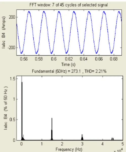
Figure 5b. Harmonic spectrum of AAG source current with balanced linear Load.
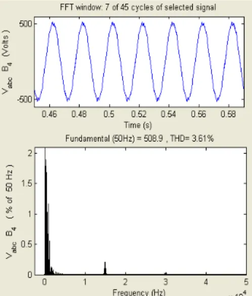
Figure 5d. Harmonic spectrum of AAG source voltage with unbalanced linear Load.
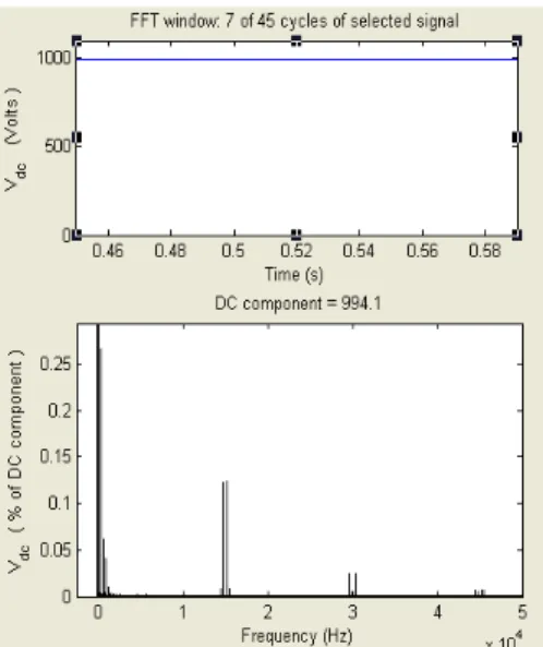
Figure 5e. Harmonic spectrum of VFC dc link voltage with balanced linear Load. Figure 5a to 5f demonstrate the harmonic spectrum of the source voltage Va B4 source current Iabc B4 and of the voltage Vdc of the dc link of VFC with balanced and unbalanced linear load and that of voltage of the dc link. The total harmonic distortion of the voltage is very small. The VFC reduces the harmonics at PCC due to the consumer loads and due to VSC to within that specified by IEEE 519 standards.
Figure 5f. Harmonic spectrum of VFC dc link voltage with unbalanced linear Load.
B. Performance of AAG with BESS based VFC Feeding nonlinear load:
Figure 6 demonstrates the performance of the BESS based VF controller for an AAG feeding balanced / unbalanced nonlinear load. The system starts with a static load of 1kW on generator bus and 1.5 kW dc load on consumer bus. The dc load is created by a 3 phase uncontrolled bridge rectifier having a resistive load on its dc side. The total load is partly supplied by the asynchronous generator and partly by the VFC. The generator bus current is maintained constant. The current of the load bus Iabc_B3 is seen as highly nonlinear. However current of the generator bus Iabc B4 is seen to remain sinusoidal. The graph of the THD Va B4 shows that the VFC is capable of reducing the harmonics generated by the load and the converter and maintain the THD of the generator bus voltage at around 3.5% when the nonlinear load is connected.
Figure 6. Dynamic performance of VFC for an AAG with balanced/unbalanced non linear load.
At 0.6 sec one phase connected to the load is opened and creating an unbalance in the load current. The phase is reconnected at 0.7 sec making the load again balanced. The unbalance in the load current produces little effect on the voltage and current of the generator bus. However the THD of the generator voltage is increased to 4%. The VFC maintains the generator voltage and current constant, which shows the load balancing aspect of the BESS based VF controller. Consumer Load is removed from the consumer load bus at 0.8 sec. After removal of the load at 0.8 sec the battery starts charging with extra generated power of the Asynchronous generator. It is shown by the change in the battery current. This demonstrates that the BESS based VF controller maintains the load on the generator bus constant and thus it is able to regulate the generator speed and hence the system frequency constant. The THD is reduced to 3%. This demonstrates the load leveling aspect of the VFC. During the entire simulation the speed (w) of the asynchronous generator is maintained almost constant at 1500 rpm. All through the simulation the generator bus voltage remains constant, which demonstrates that the VFC supplies the dynamic reactive power requirement of the asynchronous generator. This demonstrates the voltage control aspect of the VFC.
Figure 7a. Harmonic spectrum of AAG source voltage with balanced nonlinear Load.
Figure 7c. Harmonic spectrum of AAG source voltage with unbalanced nonlinear Load.
Figure 7d. Harmonic spectrum of AAG source current with unbalanced nonlinear Load. Figure 7a to 7f present the harmonic spectrum of the source voltage Va B4 source current Iabc B4 and of the voltage Vdc of the dc link of VFC with balanced and unbalanced nonlinear load and that of voltage of the dc link. The total harmonic distortion of the voltage is very small. The VFC reduces the harmonics at PCC due to the consumer loads and due to VSC to within that specified by IEEE 519 standards.
Figure 7e. Harmonic spectrum of VFC dc link voltage with balanced nonlinear Load.
Figure 7f. Harmonic spectrum of VFC dc link voltage with unbalanced nonlinear Load. 7. Conclusion
The performance of battery energy storage system based voltage and frequency controller for an autonomous asynchronous generator has been demonstrated for load leveling, voltage and frequency regulation. The VF controller proposed has also been demonstrated to have good capability for harmonic elimination and load balancing. These features of the VFC have been achieved using a simple and linear SPWM control of the CC-VSC. The SPWM control has been achieved with PI controllers. This SPWM control is much easier to implement in hardware design than other reported schemes. The simulation of the proposed controller establishes that the proposed VFC shall perform satisfactorily for an autonomous system feeding both balanced and unbalanced linear and nonlinear loads.
APPENDIX:
Asynchronous Generator:
4 kW, 415 V, 50 Hz, rpm = 1440, Squirrel cage, Pole Pair = 2,
Rs= 0.435 Ω, Rr= 0.816 Ω, Ls= 0.004H, Lr= 0.002H, Lm= 69.31mH, Inertia J = 0.089 kg.m2 No load excitation capacitor bank, delta connected, each of 550µF.
Prime Mover Characteristics
Tsh = k1 – k2*ω, k1 = 3100, and k2 = 2. DSTATCOM parameters : Lf = 800µH, Rf = 0.004 Ω, and R2= 0.1 Ω, Rs = 10k Ω, Cs = 25000 F, Cdc = 1500 µF, Kap = 5, Kai = 20 Kbp =0.0 5, Kbi = 2. 8. References:
[1] B. Singh, “Induction generator – A prospective,” Elect. Mach. Power Syst., vol. 23, pp. 163-177, 1995.
[2] R.C. Dugan, M.F. McGranaghan, S. Santoso and H. W. Beaty, “Electrical Power Systems Quality,” Tata McGraw Hill Education New Delhi, 2nd. Ed. 2010.
[3] Ann-Marie Borbely and Jan F. Kreider, “Distributed Generation The Power Paradigm for the New Millennium,” CRC press, Washington, D.C. 2001.
[4] G.K.Singh, “Self-excited induction generator research – a survey,” Electric Power System Research, vol. 69, no. 2-3, pp. 107-114, May 2004.
[5] R.C. Bansal, “Three Phase self excited induction generator: an overview,” IEEE Trans. on Energy Conversion, vol. 20, no.2, pp. 292-299, June 2005.
[6] R.C. Bansal, T.S.Bhatti and D.P. Kothari, “Bibliography on the application of Induction Generator in Non-Conventional energy systems,” IEEE Trans. on Energy Conversion, vol. EC-18, no.3, pp. 433- 439, Sept. 2003.
[7] D.B. Watson and I.P. Milner, “Autonomous and Parallel operation of self excited induction generator,” International Journal of Electrical Engineering Education, vol.22, pp.365-374, 1985.
[8] A.H. Al-Bahrani and N.H. Malik, “Steady State Analysis of parallel operated self-excited induction generator,” IEE Proceedings, Pt. C. vol. 140, no.1, pp. 49-55, 1993.
[9] E. G. Marra, and J.A. Pomilio, “Self-excited induction generator controlled by a VS-PWM bi-directional convertor for rural applications,” IEEE Trans. on Industry Applications, vol. 35, no. 4, pp.877-883, July/ August 1999.
[10] R. Bonert and S. Rajakaruna, “Self–excited induction generator with excellent voltage and frequency control,” Proc. Inst. Elect. Eng. Gen. Transm. Distrib., vol. 145. No.1 pp.33-39, January 1998.
[11] E. Suarez and G. Bortolotto, “Voltage – Frequency control of a self excited induction generator,” IEEE Trans. Energy. Convers., vol. 14, no.3, pp. 394- 401, Sept.1999.
[12] B. Singh, S.S. Murthy and S. Gupta, “Analysis and implementation of an electronic load controller for a self-excited induction generator,” Proc. Inst. Elect. Eng., Gen. Transm. Distrib., vol. 151, no.1, pp. 51-60, Jan 2004.
[13] B. Singh, S.S. Murthy and S. Gupta, “ Transient analysis of self excited induction generator with electronic load controller supplying static and dynamic loads,” IEEE Trans. Ind. Appl., vol. 41, no. 5, pp. 1194-1204, Sept.2005.
[14] B. Singh, S.S. Murthy and S. Gupta, “Analysis and design of electronic load controller for self excited induction generators,” IEEE Trans. Energy Convers. Vol. 21, no. 1, pp. 285-293, Mar. 2006.
[15] B. Singh, S.S. Murthy and S. Gupta, “A Voltage and Frequency Controller for self excited induction generator,” Elect. Power Compon. Syst. Vol. 34, no. 2, pp. 141-157, Feb 2006.
[16] J.A. Barrado and R. Grino, “Voltage and Frequency control for a self excited induction generator using a 3-phase 4-wire electronic converters,” in Proc. 12th Int. IEEE Power Electronics Motion Control Conf. Aug. 2006, pp. 1419-1424.
[17] B. Singh, S.S. Murthy and S. Gupta, “ STATCOM based voltage regulator for self-excited induction generator feeding non-linear loads,” IEEE Trans. Ind. Electron. Vol. 53, no. 5, pp. 1437-1452, Oct. 2006.
[18] B. Singh, S.S. Murthy and S. Gupta, “ Analysis and Design of STATCOM based voltage regulator for self-excited induction generator,” IEEE Trans. Energy Convers. Vol. 19, no. 4, pp. 783-790, Dec. 2004.
[19] M.B. Brennen and A. Abbondati, “ Static exciter for induction generator,” IEEE Trans. Ind. Appl. Vol. 13, no.5, pp. 422-428,Sept. 1977.
[20] J. Sun, D. Czarkowski and Z. Zabar, “Voltage Flicker Mitigation Using PWM-Based Distribution STATCOM,” IEEE Power Engg. Society Summer Meet. Vol. 1 pp. 616-621, 2002.
[21] C. Schauder and H. Mehta, “Vector Analysis and Control of Advanced Static VAR Compensators,” IEE Proc.-C, vol. 140, pp. 299-306, July 1993.
[22] W. Freitas, E. Asada, A. Morelato and W. Xu, “ Dynamic Improvement of Induction Generators Connected to Distribution Systems Using a DSTATCOM,” Proc. of IEEE int. Con. on Power System Technology, PowerCon 2002, vol.1, pp. 173-177.
[23] M. Jazayeri and M. Fendereski, “ Stabilization of Grid Connected Wind Generator during Power Network Disturbances by STATCOM,” in Proc. of IEEE 42nd Inter. Conf. Uni. Power Engg., UPEC 2007, pp. 1182-1186.
[24] H. Akagi, Y.Kangawa and A. Nabae, “Instantaneous Reactive Power Compensator Comprising Switching Devices Without Energy Storage Components,” IEEE Trans. on Industry Applications, vol. IA-20, May-June 1984.
[25] E.H. Watanbe, R.M. Stephan, M. Aredes, “ New Concepts Of Instantaneous Active and Reactive Powers in Electrical Systems with Generic Loads,” IEEE Power Delivery, vol.8, no.2, pp. 997-703, April 1993.
[26] G. Sybille, Hoang Le-Huy, “Digital Simulation of Power Systems and Power Electronics using the MATLAB/ Simulink Power System Blockset,” IEEE Power Engg. Soc., Winter Meeting 2000.
[27] Help file Discrete time integrator block MATLAB 7.1
[28] Z.M. Salameh, M.A. Casacca, W.A. Lynch, “A Mathematical Model for Lead Acid Batteries”, IEEE Trans. Energy Conversion, vol.7, no.1, pp. 93-97, 1992.
[29] Z.M. Salameh, M.A. Casacca, W.A. Lynch, “Determination of lead-acid battery capacity via mathematical modeling technique”, IEEE Trans. Energy Conversion, vol.7, no.3, pp. 442-446, 1992.
[30] M. Chen, G.A. Rincon-Mora, “Accurate Electrical Battery Model Capable of Predicting Runtime and I-V performance”, IEEE Trans. Energy Conversion, vol.21, no.2, pp. 504-511, 2006.
[31] M. Ceraola, “New Dynamic models of lead–acid batteries”, IEEE Trans of Power System, vol.15, no. 4, pp. 1184-1190, 2000.
[32] N. Mohan, T.M. Undeland, W.P. Robbins, Power Electronics Converters, Application, and Design, third ed., Wiley India, New Delhi, 2007
[33] Bhim Singh, Ambrish Chandra, “Battery Based Voltage and Frequency Controller for Parallel Operated Isolated Asynchronous Generators”, IEEE international symposium on Industrial Electronics, ISIE 2007, pp 883-888.
Associatio the Depar His field applicatio refereed j Journals)] Conferenc on Semic generator He has be External E Dr. Bisw National Award fo He is a L Engineers (India) an His name Practices Paper on major inte associated technolog Engineeri a Professo Amb Univ India indus prese Instit electr IEEE on of Compute Sujit Electr the M Institu Depar during Depar as a R rtment of Elect s of interest a ons, magnetics journals [of w ] and 62 paper ces) and about conductor Pow r. een a member Expert to sever was received s Science Acad r “Outstanding Life member s (India), a Fel nd a Senior Me e is recorded on and Requirem gate drive tech ernational man d as a consul gies in the area Bhim degree India, degree 1979, Electr Reade and, in ing, Indian Inst or. He has auth
barnath Baner ersity of Roork a. He has 22 y
stries like pow ently associate tute of Techn ronics, power E, a life memb er Electronics a Kumar Bis rical Engineeri M.E. degree (wi ute of Scienc rtment of Elect g a period in rtment of Elect Reader, where trical Engg, Jad
are static pow and applied e which 8 are in rs in National t 42 circuit idea wer Converter of several Nat ral Governmen several awards demy Medal fo g contribution i of the Solar E llow of the Inst ember of the In n the panel that ments for Harmo
hnique for IGB nufacturers – In ltant with sev
of Power Elec Singh was b e in electrical
and the M.Tec e from the Ind and 1983, re rical Engineeri er in March 19 n February 199 titute of Techn hored more tha
rji He received kee, India and ears of experie wer plants, ste ed with the E nology Kolkat systems, stat ber of Instituti and Electrical E was received ing from Jadav ith Distinction ce, Bangalore. trical Engineer which he rec trical Engineer he is currently davpur Univers wer conversion electronics. H IEEE Transac and Internatio as/popular elec r Circuits and tional and Inter nt of India orga s, amongst wh or young Scie in the field of P Energy Society titution of Elec nstitution of Ele t finalized the I onic Control in BT is referred i nternational Re veral major in ctronics and Dr orn in Rahman engineering f ch. degree in p dian Institute o espectively. In ing, University 88. In Decemb 94, an Associat nology, New D an 200 researc d B.E. degree in M.E. degree fr ence in contro eel industries Electrical Dep ta. His field ic VAr comp on of Enginee Engineers. the B.E.E. vpur University n) in Electrical Since then ring, Indian Ins ceived PhD. H ring, Jadavpur y a Professor. H sity. n, electrical d e has authored tions and 3 in nal Conferenc ctronics article d has applied rnational Com anizations.
hich the most entists in 1987 Power Electron y of India, a ctronics and Te ectrical & Elec IEEE Standard n Electrical Pow in the Applicat ectifier and ST ndustries in In rives. npur, India, in from the Univ power apparatu of Technology, July 1983, h y of Roorkee, ber 1990, he be te Professor in elhi, India. Sin ch papers in th n electrical eng from University l systems of v and chemical partment of M of interest in ensation. He ers (India) and
degree (with y, Kolkata, in Engineering fr , he was emp stitute of Scien He joined the University, Ko He has served drives, power d 33 research p n IEE Proceedi es (of which 4 es. He also hol for a patent mmittees and ha
t prestigious a 7 and the IET
nics” in 2004. Fellow of the elecommunica ctronics Engine d 519–1992 : “R wer Systems”. tion Notes for T-Microelectro ndia to develo n 1956.He rece versity of Roor us and systems, , New Delhi, I he joined the D as a Lecture ecame an Assi n the Departmen nce August 199 e areas of pow gineering from y of Rajasthan, various process plants. He is Meghnad Saha nclude, power is member of d a member of Honours) in 1978 and then from the Indian ployed in the nce, Bangalore, faculty of the olkata, in 1987 as the Head of semiconductor publications in ings (now IET 48 are in IEEE lds two patents on a special as served as an are the Indian TE-Bimal Bose e Institution of ation Engineers eers (USA). Recommended One Research IGBTs by two nics. Has been op indigenous
eived the B.E rkee, Roorkee, , and the Ph.D India, in 1977, Department of r, becoming a stant Professor nt of Electrical 97, he has been wer electronics, m , s s a r f f n n n e , e 7 f r n T E s l n n e f s d h o n s . , . , f a r l n ,
CAD and analysis of electrical machines, active filters, self-excited induction generators, industrial electronics, static VAR compensation, and analysis and digital control of electric drives. Prof. Singh is a Fellow of the Institution of Engineers (India) and Institution of Electronics and Telecommunication Engineers, and a Life Member of the Indian Society for Technical Education, System Society of India, and National Institute of Quality and Reliability.