Version: Accepted Version
Article:
Hawes, M. orcid.org/0000-0002-3742-3416, Mihaylova, L. orcid.org/0000-0001-5856-2223,
Septier, F. et al. (1 more author) (2017) Bayesian Compressive Sensing Approaches for
Direction of Arrival Estimation with Mutual Coupling Effects. IEEE Transactions on
Antennas and Propagation, 65 (3). pp. 1357-1368. ISSN 0018-926X
https://doi.org/10.1109/TAP.2017.2655013
© 2017 IEEE. Personal use of this material is permitted. Permission from IEEE must be
obtained for all other users, including reprinting/ republishing this material for advertising or
promotional purposes, creating new collective works for resale or redistribution to servers
or lists, or reuse of any copyrighted components of this work in other works. Reproduced
in accordance with the publisher's self-archiving policy.
[email protected] https://eprints.whiterose.ac.uk/
Reuse
Unless indicated otherwise, fulltext items are protected by copyright with all rights reserved. The copyright exception in section 29 of the Copyright, Designs and Patents Act 1988 allows the making of a single copy solely for the purpose of non-commercial research or private study within the limits of fair dealing. The publisher or other rights-holder may allow further reproduction and re-use of this version - refer to the White Rose Research Online record for this item. Where records identify the publisher as the copyright holder, users can verify any specific terms of use on the publisher’s website.
Takedown
If you consider content in White Rose Research Online to be in breach of UK law, please notify us by
Bayesian Compressive Sensing Approaches
for Direction of Arrival Estimation
with Mutual Coupling Effects
Matthew Hawes
a, Lyudmila Mihaylova
aand Franc¸ois Septier
b, Simon Godsill
ca
Department of Automatic Control and Systems Engineering, University of Sheffield, S1 3JD, UK
bIMT Lille Douai, Univ. Lille, CNRS, UMR 9189 - CRIStAL, F-59000 Lille, France
cEngineering Department, University of Cambridge, UK
{
m.hawes, l.s.mihaylova
}
@sheffield.ac.uk, [email protected], [email protected]
Abstract—The problem of estimating the dynamic direction
of arrival of far field signals impinging on a uniform linear array, with mutual coupling effects, is addressed. This work proposes two novel approaches able to provide accurate solu-tions, including at the endfire regions of the array. Firstly, a Bayesian compressive sensing Kalman filter is developed, which accounts for the predicted estimated signals rather than using the traditional sparse prior. The posterior probability density function of the received source signals and the expression for the related marginal likelihood function are derived theoretically. Next, a Gibbs sampling based approach with indicator variables in the sparsity prior is developed. This allows sparsity to be explicitly enforced in different ways, including when an angle is too far from the previous estimate. The proposed approaches are validated and evaluated over different test scenarios and compared to the traditional relevance vector machine based method. An improved accuracy in terms of average root mean square error values is achieved (up to 73.39%for the modified relevance vector machine based approach and 86.36% for the Gibbs sampling based approach). The proposed approaches prove to be particularly useful for direction of arrival estimation when the angle of arrival moves into the endfire region of the array.
Index Terms—Dynamic DOA estimation, Bayesian compressive
sensing, Kalman filter, Gibbs sampling, Relevance vector machine
I. INTRODUCTION
Direction of arrival (DOA) estimation is the process of determining which direction a signal impinging on an array has arrived from. Commonly used methods of solving this problem are: MUSIC [1], [2], ESPRIT [3]–[6] and the maximum likelihood DOA estimator [7]–[9]. However, these methods have some disadvantages, in particular they require knowledge of the number of signals present beforehand and evaluation of a covariance matrix of the array output (adding computational complexity).
Compressive Sensing (CS) theory says that when certain conditions are met it is possible to recover signals from fewer measurements than used by traditional methods [10], [11]. Hence, CS can be applied to the problem of DOA estimation [12]–[15] by splitting the angular region into N potential DOAs, where onlyL << N of the DOAs have an impinging signal (alternatively N−L of the angular directions have a
zero-valued impinging signal present). These DOAs are then estimated by finding the minimum number of DOAs with a non-zero valued impinging signal that still give an acceptable estimate of the array output.
The problem can also be converted into a probabilistic form and solved via Bayesian compressive sensing (BCS) [16], implemented with a relevance vector machine (RVM) [17]– [19]. Such a method has been used to solve the problem of static DOA estimation [20], [21], where a belief of having a sparse received signal is made and the most likely values found.
The Kalman filter (KF) can be used to track dynamic DOAs, with the angular range narrowed to focus in more closely on the DOA estimate from the previous iteration [22]. However, this prevents directly working with the measured array signals and introduces an additional stage of having to reevaluate the steering vector of the array at each iteration of the KF. Hierarchical KFs have been used to track dynamic sparse signals [23], [24], where the predicted mean of the signals at each iteration is taken as the estimate from the previous iteration and the hyperparameters are estimated using BCS, hence the term Bayesian compressive sensing Kalman Filter (BCSKF).
However, a problem remains when a BCSKF is applied to dynamic DOA estimation with a uniform linear array (ULA). The estimation accuracy can be reduced when the DOA approaches the endfire region of the array, i.e. when the impinging signal arrives parallel to or almost parallel to the array. This can be particularly problematic when there is a lot of noise present.
d
d
θ θ θ
y
kdM=(M−1)∆
[image:3.595.83.266.106.274.2]∆
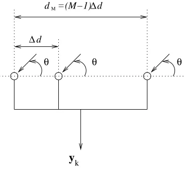
Fig. 1. Linear array structure being considered, consisting ofM antennas with a uniform adjacent antenna separation of∆d.
The contributions of this paper are: i) A BCSKF with a modified RVM, where the traditional sparsity prior is replaced with a belief that the estimated signals will instead match predicted signal values, is proposed. The result of this new prior is that a new posterior distribution and marginal likeli-hood have been derived. Initial results for this method using a signal model without mutual coupling have been reported in [27]. ii) A Gibbs sampling approach is proposed. In this approach zero valued signals can be explicitly enforced when there is too large a change in DOA in order to alleviate the estimation accuracy problem for the endfire region of the array.
iii) A comprehensive performance evaluation is provided, with
the proposed methods being compared to a BCSKF using the traditional RVM approach. Significant improvements in terms of the average root mean square error (RM SE) values are observed (up to 73.39% for the BCSKF with modified RVM and up to 86.36% for the Gibbs sampling approach).
The remainder of this paper is structured in the following manner: Section II gives details of the proposed estimation methods, including the array model with mutual coupling effects (II-A), the modified RVM framework for BCS (II-B), the BCSKF (II-C) and the Gibbs sampling implementation (II-D). In Section III an evaluation of the effectiveness of the proposed approaches is presented and conclusions are drawn in Section IV.
II. PROPOSEDESTIMATIONMETHODS
A. Array Model
A narrowband ULA structure consisting of M omnidirec-tional antennas, with identical responses is shown in Figure 1. Here, a plane-wave signal mode is assumed, i.e. the signal impinges upon the array from the far field and the angle of arrival is limited to 0◦ ≤ θ ≤ 180◦. The distance from the first antenna to subsequent antennas is denoted as dm for
m = 1,2, . . . , M, with d1 = 0, i.e. the distance from the
first antenna to itself. Note, these values are multiples of a uniform adjacent antenna separation of ∆d.
The steering vector of the array is given by
a(Ω, θ) = [1, e−jµ2Ω cosθ, . . . , e−jµMΩ cosθ]T, (1)
where Ω = ωTs is the normalised frequency with Ts being the sampling period,µm= cTsdm form= 1,2, . . . , M,c gives the wave propagation speed and {·}T denotes the transpose operation.
The array output, yk, at time snapshot kis then given by yk =Astxk+nk, (2) where xk= [xk,1, xk,2, ..., xk,N]T ∈CN×1 gives the received
source signals, nk = [nk,1, nk,2, ..., nk,M]T ∈ CM×1 is a noise term, given by a zero mean multivariate Gaussian ran-dom variable and Ast = [a(Ω, θ1),a(Ω, θ2), ...,a(Ω, θN)] ∈
CM×N is the matrix containing the steering vectors for each angle of interest. Note, N is the number of points in the grid of potential DOAs the angular region has been split into. However, onlyL << N of these angular directions will have an impinging signal present.
In practice there will also be mutual coupling effects present, which alter the pattern of an individual antenna as compared to if it was being used on its’ own. As a result (2) has to be altered to account for this fact. A mutual coupling matrix is used to achieve this [26], by giving the true steering vector matrix as
A=MMCAst. (3) Here MMC ∈CM×M is the mutual coupling matrix given by
MMC=
1 m2 . . . mD−1 . . . mM
m2 1 m2 . . . . .. ...
..
. m2 1 m2 . . . mD−1
mD−1 . . . . .. . .. . .. ...
..
. . .. . . . m2 1 m2
mM . . . mD−1 . . . m2 1
.
(4)
In (4) the mutual coupling coefficients are given by
mi = ρiexp{jφi} for i = 2, ..., D−1, D, ..., M, where
ρi and φi give the amplitude and phase, respectively. The variableD places a limit on the separation between antennas above which there will be no mutual coupling effects. In other words wheni > D, thenρi= 0. This then gives the following:
yk = MMCAstxk+nk
= Axk+nk. (5) Equation (5) can then be split into real and imaginary components (given byR(·)andI(·), respectively) as follows
˜
yk = ˜A˜xk+ ˜nk
R(yk)
I(yk)
=
R(A) −I(A)
I(A) R(A)
R(xk)
I(xk)
+
R(nk)
I(nk)
.
dimensions of ˜yk are increased. A similar relationship exists between A andA, x˜ k and˜xk and nk andn˜k.
B. Modified Relevance Vector machine for DOA Estimation
The aim is to now find a solution for ˜xk which gives the closest possible match to a predicted set of signal values. To achieve this one can follow a modified RVM framework [27], by evaluating the following
˜
xk,opt= maxP(˜xk, σk2,pk|˜yk,˜xp), (7) where σ2
k is the variance of the Gaussian noise nk, pk = [pk,1, pk,2, ..., pk,2N]T contains the hyperparameters that are to be estimated and ˜xp = [R(xp)T,I(xp)T]T = [R(xp,1), ...,R(xp,N),I(xp,1), ...,I(xp,N)]T holds the pre-dicted values of ˜xk.
From (6) it is possible to find:
P(˜yk|˜xk, σk2) = (2πσk2)−Mexp n
− 1
2σ2||˜yk−A˜˜xk|| 2 2
o
. (8)
The traditional RVM would now apply a belief that ˜xk is sparse. However, here this is changed to a belief that ˜xk will match the predicted signals˜xp:
P(˜xk|pk,˜xp) = (2π)−N|Pk|
1 2
× expn−1
2(˜xk−˜xp) TPk(˜x
k−˜xp) o
.(9)
Note, when ˜xp = [0,0, ...,0]T then (9) reverts to the hierar-chical prior used in the traditional RVM [16], [17] and |Pk| indicates the determinant of Pk, where Pk=diag(pk).
It is also necessary to define the hyperparameters over pk and σ2
k. There are various possibilities for the structuring of the priors on pk, which represent mixing parameters in a scale mixture of normals representation of the marginal distribution of xk, which will here be in the Student-t family, see e.g. [28]. One possibility would be to treat the complex components of xk as complex Student-t distributed, as detailed in [29], [30]. However, this work treats the real and imaginary components of xk as independent Student-t distributed random variables, and hence there are independent Gamma priors for the mixing variablespk,n over all real and imaginary components of xk:
P(pk) =
2N Y
n=1
G(pk,n|β1, β2). (10)
A Gamma prior can also be used forσ2
k
P(σ2
k) =G(σ−
2
k |β3, β4), (11)
whereβ1, β2, β3 andβ4 are scale and shape priors.
It is known that
P(˜xk, σk2,pk|˜yk,˜xp) =P(˜xk|˜yk, σ
2
k,pk,˜xp)P(σ
2
k,pk|˜yk,˜xp) (12) and
P(˜xk|˜yk, σ
2
k,pk,˜xp) =
P(˜yk|˜xk, σ2k)P(˜xk|pk,˜xp)
P(˜yk|σ2
k,pk,˜xp)
= (2π)−N|Σ|−1/2exp
(
−1
2(˜xk−µ) TΣ−1
(˜xk−µ) )
,(13)
where the covariance matrix and the mean are given by
Σ= (σ−2
k A˜ T˜
A+Pk)−1 (14) and
µ=Σ(σk−2A˜ T
˜
yk+Pk˜xp), (15) respectively. Note, the maximum of (13) is the posterior mean µ. For a derivation of (13) please see Appendix A.
Similarly to [17], the probability P(σ2
k,pk|˜yk,˜xp) can be represented in the following form:
P(σk2,pk|˜yk,˜xp)≈ P(˜yk|σ
2
,p,˜xp)P(σk2)P(pk)P(˜xp), (16)
where P(˜xp) is constant as fixed values are used and the second two terms on the right of are constant if β1 =
β2 = β3 = β4 = 1×10⁻⁴ as in [17]. Therefore,
max-imisingP(σ2
k,pk|˜yk,˜xp)is roughly equivalent to maximising
P(˜yk|σ2
k,pk,˜xp). This can be achieved by a type 2 max-imisation of its logarithm, which is given by (please see Appendix B):
L(σ2
k,pk) = log (
(2πσ2
k)−M|Σ|
1
2|Pk|12exp
−1
2
× (˜yTkB˜yk+ ˜xTpC˜xp−2σk2˜yTkA˜ΣPk˜xp)
)
= −1
2
2Mlog(2π) + 2Mlogσ2
k−log|Σ| −
log|Pk|+σk−2||˜yk−A˜µ||
2
2+µTPkµ
+˜xTpPk˜xp−˜xTpPkµ
, (17)
where B= (σ2
kI+ ˜AP −1
k A˜ T
)−1 and C=P
k−PTkΣPk. This is now differentiated with respect topk,n andσ−k2 to obtain the update expressions
pnewk,n =
γn
µ2
n+ ˜x2p,n−˜xp,nµn
, (18)
whereγn= 1−pk,nΣnn,Σnnis thenth diagonal element of
Σ and
σ2
k,new=
||˜yk−A˜µ||22
2M −P n
γn
. (19)
For the derivation of (18) and (19) please see Appendix C. The maximisation is then achieved by iteratively findingΣ
andµ, followed by pnew
k,n forn= 1, ..., N andσk,new2 until a convergence criterion is met [16], [17]. In other words, the new estimates for the noise variance and precision hyperparameters found from (19) and (18) are then used in (14) and (15) to find new estimates of the covariance matrix and mean of the distribution in (13). Note that when ˜xp = [0,0, ...,0]T the update expressions match those used by the traditional RVM. The final estimate of the received signals is then given by
˜ xk,opt=
A˜ T˜
A
σ2
k,opt
+Pk,opt −1A˜
T ˜ yk
σ2
k,opt
+Pk,opt˜xp
(20)
whereσ2
the estimated signals as
xk,opt,n= ˜xk,opt,n+jx˜k,opt,N+n, (21)
wheren= 1,2, ..., N.
The thresholding scheme in [20] can then be applied to keep theL˜ most significant signals. To do this find the total energy content of the estimated received signals and then sort them. A threshold value,η, is then defined as a percentage of the energy content that is to be retained. Starting with the most significant estimated signal, the estimated signals are summed until the threshold is reached and the remaining signals are then set to be equal to 0. The remaining non-zero valued signals then give the DOA estimates and L˜ is an estimate of the number of far field signals impinging on the array.
C. Bayesian Compressive Sensing Kalman Filter
In order to track the changes in the DOA estimates at each time snapshot the modified RVM based DOA estimation procedure detailed above is combined with a Bayesian KF, giving a BCSKF for DOA estimation [27]. The signal model described above is again used along with the prediction
˜
xk|k−1= ˜xk−1|k−1+∆x Σk|k−1=Σk−1+P−k1
˜
yk|k−1= ˜A˜xk|k−1 ˜ye,k= ˜yk−˜yk|k−1 (22)
and update steps ˜
xk = ˜xk|k−1+Kk˜ye,k Σk|k = (I−KkA˜)Σk|k−1
Kk=Σk|k−1A˜
T
(σ2kI+ ˜AΣk|k−1A˜
T
)−1 (23)
of the BCSKF. Here, k|k −1 indicates prediction at time instance k given the previous measurements and ∆x is
de-termined by the assumed DOA change. Note,∆x is fixed by
the predetermined constant motion rather than being a random noise term. For example, if the angular range is sampled every 1◦and the DOA is assumed to increase by2◦then∆x will be selected to increase the index of the non-zero valued entries in ˜xk−1|k−1 by two to give the index of the non-zero valued
entries in˜xk|k−1.
At each time snapshot it is necessary to estimate the noise variance and hyperparameters in order to evaluate the prediction and update steps of the BCSKF. This is done by considering the log likelihood function given by
L(σ2
k,pk) = − 1 2
2Mlog(2π) + 2Mlogσ2
k−log|Σ|
−log|Pk|+σk−2||˜ye,k−A˜µ||
2
2+µTPkµ
+˜xTk|k−1Pk˜xk|k−1−˜xTk|k−1Pµ
, (24)
which can be optimised by following the procedure described in Section II-B. In other words we apply the modified RVM framework to ˜ye,k, using the KF prediction ˜xk|k−1 as the
expected estimate values ˜xp.
It is worth noting that the continued accuracy of the pro-posed BCSKF relies on the accuracy of the initial estimate and the parameter values selected. If the initial estimate (made using the framework described in Section II-B and ˜
xp = [0,0, ...,0]T) of the received signals is accurate and
sparse, then the priors that are enforced will ensure this continues to be the case. However, an inaccurate initial DOA estimate or poorly matched expected DOA change can lead to the introduction of inaccuracies in subsequent estimates. Similarly, if the initial estimate of the received signals is not sparse then subsequent estimates are likely to not be sparse. As a result, care should be taken when choosing the initial parameter values and determining the likely DOA change.
D. Gibbs Sampling for DOA Estimation
The method described in the previous sections based on a BCSKF with a modified RVM required the use of prior knowledge of the predicted change in DOA. However, in practice this may not always be known, making it important to have an alternative method that can still give improved accuracy for the endfire region.
This work proposes using a sparsity prior which is given as a combination of a point mass concentrated at zero (Dirac delta function) and a zero mean Gaussian distribution, [31]– [33], giving
P(˜xk|pk,˜zk) =
2N Y
n=1
(1−˜zk,n)δ0+ ˜zk,nN(˜xk,n|0, pk,n), (25)
where˜zk = [zTk,zTk]T and zk= [zk,1, zk,2, ..., zk,N]T. Note,˜zk,nis the indicator variable forx˜k,n and determines which of the two components in (25) is selected. When ˜
zk,n = 0, the value of x˜k,n is determined solely by the point mass concentrated at zero. As a result, x˜k,n = 0 and sparsity is explicitly introduced. Alternatively, whenz˜k,n= 1 the value ofx˜k,n is determined by the Gaussian distribution allowing a non-zero valued estimate. The repetition of zk in ˜zk means that the same indicator variable is used for both the real and imaginary parts of each entry in xk.
This indicator value can also be used to address the endfire accuracy problem by selecting the value ofzk,n= 0if|n−i|>
j. Here i is the index of the closet non-zero valued estimate from the previous time snapshot and j defines a maximum allowed change in the DOA estimate. Onlyn= 1,2, ..., N is considered to get the entries for zk, with˜zk then being found as previously stated.
This leaves the following
zk,n= (
z1
k,n if|n−i| ≤j,
z2
k,n if|n−i|> j,
(26)
wherez1
k,n andzn2 are defined by the following Beta distribu-tions
z1
k,n = B(zk,n1 |β51, β 1 6),
z2
k,n = B(z
2
k,n|β
2 5, β
2
6). (27)
In order to enforce zero-valued estimates when|n−i|> j, it is necessary to selectβ2
5andβ62to ensure a zero-valuedzk,nis preferred. However, when|n−i| ≤j it is necessary to choose
β1
5 and β61 so that the chances of zk,n = 0and zk,n = 1are equal. This can be achieved by
P(z1
k,n|β5, β6) = B(zk,n1 |β5, β6),
P(z2
k,n|β5, β6) = B
z2
k,n|β5−
1
j, β6+
1
j
whereβ5=β6= 1.
The posterior distribution of ˜xk can be written as [33]
P(˜xk|˜yk, σ
2
k,pk,˜zk)∝ nY2N
n=1
[(1−z˜k,n)δ0+ ˜zk,n
×N(˜xk,n|0, pk,n)] o
N(˜yk|A˜x˜k, σ−k2). (29)
Now also define A˜n as being the entries in A relating to˜ the index n and A˜−n are the entries of A excluding the˜ entries relating to index n (and similarly for ˜xk). Then as per Appendix D this gives
P(˜xk,n|˜yk,˜xk,−n, σk2,pk,˜zk) = (1−zˆk,n)δ0+ ˆzk,n
× N(˜xk,n|µˆk,n,pˆk,n)(30), ˆ
pk,n = pk,n+p0A˜
T
nA˜n, (31) ˆ
µk,n = pˆ−k,n1p0A˜
T
n˜yk,n, (32) ˆ
zk,n 1−zˆk,n
= z˜k,n 1−z˜k,n
× N(0|0, pk,n) N(0|µ˜k,n,pˆk,n)
, (33)
wherep0= 1/σk2and˜yk,n= ˜yk−A−˜ n˜xk,−n.
There are two further posterior distributions that have to be considered. That is the distributions forpk,n andp0which are
given by
P(pk,n|xk−1) =G(β1+||xk−1,nj||0, β2+||xk−1,nj||22) (34)
and
P(p0|˜yk,x˜k) =G(β3+M, β4+
1
2||˜yk−A˜˜xk||
2
2), (35)
respectively. Note, in (34) xk−1,nj gives the entries within xk−1 that have an index within the distancej of indexn. By
using x rather than ˜x to find xk−1,nj it guarantees the same value of ||xk−1,nj||22 and ||xk−1,nj||0 for both the real and
imaginary components.
As a result the Gibbs sampling steps are as detailed below: 1) Sample x˜k,n fromP(˜xk,n|˜yk,x˜k,−n, σk2,pk,˜zk). 2) Sample pk,n fromP(pk,n|xk−1).
3) if n ≤ N then Sample z1
k,n from P(zk,n1 |β5, β6),
else z1
k,n=zk,n1 −N.
4) if n ≤ N then Sample z2
k,n from P(zk,n2 |β5, β6),
else z2
k,n=zk,n2 −N.
5) Sample p0 from P(p0|˜yk,˜xk).
These steps are done for each of the T iterations of the Gibbs sampler, where the first TBI iterations are the burn-in iterations. The fburn-inal estimate of the received array signals is then given by the mean values of the final T − TBI iterations [32]. The DOA estimate can then be found using the previously described thresholding scheme (see II-B), with the remaining non-zero valued estimates corresponding to the DOA estimates.
Note, the performance of this method will again heavily depend on the accuracy of the first estimate. As a result, it is possible to use the traditional BCS DOA estimation method (Section II-B with˜xp= [0,0, ...,0]T) to ensure an as accurate as possible intial estimate at the first time snapshot. The
proposed Gibbs sampling based method can then be used at the subsequent time snapshots to get the next DOA estimate.
III. PERFORMANCEEVALUATION
In this section a comparison in performance of the proposed methods and the traditional RVM based BCSKF method will be made over five example scenarios, under the same test conditions. Firstly, an example is considered where the initial DOA starts outside of the endfire region and then moves into it. Secondly, an example is given where the DOA remains out of the endfire region. In the third scenario the initial DOAs and the signal values are randomly generated. Then the evaluation will also consider the scenario where there is a mismatch between the actual and assumed change in DOA. Finally, the evaluation will consider a random change in DOA at each time snapshot. This means that ∆x which is selected for the modified RVM based BCSKF will not be a true reflection of how the DOA actually changes for the last two examples.
Note, the term traditional RVM based BCSKF method means the entries of Pk in the prediction step of the BCSKF are found using the RVM optimisation method as detailed in [16], [17]. In other words this is the method detailed in Section II-B with˜xp=0. All of the examples are implemented in Matlab on a computer with an Intel Xeon CPU E3-1271 (3.60GHz) and 16GB of RAM.
The performance of each method will be measured using theRM SE in the DOA estimate. This is given by
RM SE= v u u u u t
Q P q=1
˜
L P
l=1
|θl−θˆl|2
QL˜ , (36)
whereθl is the actual DOA, θˆl is the estimated DOA and Q is the number of Monte Carlo simulations carried out, with
Q= 100being used in each case. This gives a measure of the estimation accuracy and the computation time will be used as a measure of the complexity of each method.
For the Gibbs sampling method a burn-in period of 250 iterations is used and then 50 further iterations used to find the final estimate of the received array signals. When a distance ofj = 5◦ is exceeded a zero-valued estimate of the received signals is enforced in order to alleviate the endfire accuracy problem.
For all the design examples considered the selection of
σ2
k = 0.4as the noise variance is used, with an initial estimate of the noise variance given byσ2
k,0= 0.1. The array geometry
being used is that of a ULA with M = 20 antennas and an adjacent antenna separation of λ2, where λis the wavelength of the signal of interest. This gives an array aperture of9.5λ. For the mutual coupling matrix a value ofD= 3 is selected, meaning that a separation of1.5λor greater gives negligible mutual coupling effects. The values ρ1 = 0.65, ρ2 = 0.25,
φ1=π/7andφ2=π/10are then also used. Finally, in each
TABLE I
PERFORMANCE SUMMARY FOR THE ENDFIRE REGION EXAMPLE.
AverageRM SE Average Computation Method (degrees) Time (seconds)
RVM 19.88 0.76
Modified RVM 6.46 0.98
Gibbs 3.82 17.83 excluding burn-in 107.84 including burn-in
1 2 3 4 5 6 7 8 9 10 11 12 13 14 15 16 17 18 19 20 0
5 10 15 20 25 30
Time Snapshot
RMSE (degrees)
[image:7.595.323.551.137.358.2]RVM Modified RVM Gibbs
Fig. 2. RM SEvalues for the endfire region example.
A. Endfire Region
For this example the initial DOA of the signal isθ= 20◦, which then decreases by1◦at each time snapshot. The signal value at each snapshot is set to be 1. Table I summarises the performance of the three methods for this example, with the
RM SEvalues at each time snapshot being shown in Figure 2. Here it can be seen that there has been a significant decrease in the average RM SE values for both the modified RVM method (67.51%improvement) and the Gibbs sampling based method (80.78% improvement). Overall this suggests that a more accurate estimate of the DOA is possible. It is worth noting that there has still been an increase in the RMSE for the modified RVM based approach in the endfire region of the angular range. However, this has come much later on the than for the traditional RVM based approach (indicating a degradation in performance for a smaller angular range) and the maximumRM SE value reached is lower (indicating the degradation is less severe).
These improvements have come at the cost of an increased computation time in both instances. For the modified RVM method this increase is insignificant as the average compu-tation time is still less than one second. The increase for the Gibbs sampling based method is larger, illustrating an increase in computational complexity. However, it is worth remembering that this increase has resulted in a more accurate DOA estimate being achieved without prior knowledge about what the change in DOA will be.
In this instance the results suggest that one of the two proposed methods should be used when the estimated DOA approaches the endfire region of the array. If the change in DOA is known in advance and computational complexity is a primary concern then the modified RVM based method is the most suitable (a more accurate estimate can be achieved
TABLE II
PERFORMANCE SUMMARY FOR THE ENDFIRE REGION EXAMPLE WITH REDUCED ADJACENT ANTENNA SEPARATIONS.
AverageRM SE Average Computation Method (degrees) Time (seconds)
RVM 2.21 0.98
Modified RVM 0.86 1.25
Gibbs 3.02 16.81 excluding burn-in 101.65 including burn-in
1 2 3 4 5 6 7 8 9 10 11 12 13 14 15 16 17 18 19 20 0
2 4 6 8 10 12 14 16 18
Time Snapshot
RMSE (degrees)
RVM Modified RVM Gibbs
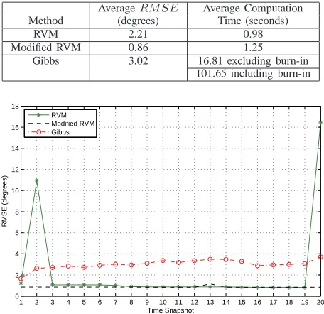
Fig. 3. RM SEvalues for the endfire region example with reduced antenna separation.
without a large increase in computation time). However, when this information is not available, or computational complexity is not a concern, it is possible to get a significant improvement in accuracy (at the cost of computation time) using the Gibbs sampling based method.
In the previous simulation an adjacent antenna separation of
λ/2is used as it is known that this is the largest separation that can be used while still avoiding a degraded performance due to the introduction of grating globes [34]. However, an example of what the relative performance of the methods is when a smaller adjacent antenna separation will now be considered.
In this instance an adjacent antenna separation of λ/4 is selected. As the array aperture is kept constant (to allow a fair comparison between adjacent antenna separation sizes) this means the number of antennas is given byM = 39. This also means a value ofD= 9is required to keep the same distance limits on mutual coupling occurring. The values ofρi andφi are then selected to be uniformly spread over the range of 0.65 to 0.25 and π/7 to π/10, respectively. The remaining parameters are kept constant and the same test scenario as for the previous example is used.
The performances of each of the methods in this instance are summarised in Table II and Figure 3, respectively. Here it can be seen that the larger number of antennas used has resulted in a lower average RM SE values for all three of the methods. In this instance only the modified RVM method has performed better that the traditional RVM based method when comparing averageRM SE values (decrease in average
RM SE of 61.09%). However, by looking at the maximum
TABLE III
PERFORMANCE SUMMARY FOR THE NON-ENDFIRE REGION EXAMPLE.
AverageRM SE Average Computation Method (degrees) Time (seconds)
RVM 2.91 0.73
Modified RVM 1.85 0.78
Gibbs 1.46 13.08 excluding burn-in 79.57 including burn-in
1 2 3 4 5 6 7 8 9 10 11 12 13 14 15 16 17 18 19 20 0
2 4 6 8 10 12
Time Snapshot
RMSE (degrees)
RVM Modified RVM Gibbs
Fig. 4. RM SEvalues for the non-endfire region example.
to3.71◦).
It is worth noting that such an array configuration is unlikely to be used in practice. This is due to the costs associated with the number of antennas required. As a result, the remaining examples will stick to the adjacent antenna separation ofλ/2 and associated parameters previously defined.
B. Non-Endfire Region
For this example the initial DOA is θ = 100◦ with the DOA increasing by1◦ at each time snapshot, with the signal value remaining constant at -1. The performance of the three methods is summarised in Table III, with theRM SE values illustrated in Figure 4.
In this instance it can be seen that there has not been as large an increase inRM SE for the traditional RVM method, as the DOA does not enter the endfire region. However, both the modified RVM and Gibbs sampling based methods have managed to achieve improvements in averageRM SE values of 36.42% and50.00%, respectively. For the Gibbs sampling based method this comes at the expenses of an increase in computation time, whereas the time for the modified RVM based method is comparable to the traditional RVM based method. As with the previous test scenario this would suggest that the modified RVM based method should be used when the expected DOA change information is available and the Gibbs sampling based method when this is not the case, or when computational complexity is not a major concern.
C. Random Initial DOA
Next consider the case where the initial DOA is randomly chosen from the entire angular range and increased by 1◦ at each time snapshot. The signal value is randomly selected
TABLE IV
PERFORMANCE SUMMARY FOR THE RANDOM INITIALDOAEXAMPLE.
AverageRM SE Average Computation Method (degrees) Time (seconds)
RVM 12.10 0.74
Modified RVM 3.22 0.86
Gibbs 2.89 13.88 excluding burn-in 84.19 including burn-in
1 2 3 4 5 6 7 8 9 10 11 12 13 14 15 16 17 18 19 20 0
5 10 15 20 25
Time Snapshot
RMSE (degrees)
RVM Modified RVM Gibbs
Fig. 5. RM SEvalues for the random initial DOA example.
as ±1 for each simulation and remains constant as the DOA changes.
Table IV and Figure 5 summarise the performance of the various methods in this instance. Again, it can be seen that the modified RVM based method has offered improvements in terms of RM SE(73.39%), without a significant increase in computation time. The Gibbs sampling based method has also given an estimation accuracy improvement (76.12%) and has even outperformed the modified RVM based method, without prior knowledge of how the DOA was going to change. However, this has come at the expense of an increased computation time.
D. Mismatched Actual and Assumed DOA Change
This subsection compares the performances of the estima-tion methods for two situaestima-tions where the actual change in DOA is not known. First, consider the case where there is an initial DOA of θ = 100◦ which increases by 1◦ for 9 time snapshots before decreasing by1◦for the remaining time snapshots. In this instance, assume a constant signal value of 1 throughout.
The performance comparison is now made between the traditional RVM based method, the modified RVM based method with the assumed DOA change set to a constant increase of 1◦, the modified RVM based method with the assumed DOA change set to a constant decrease of 1◦ and the Gibbs sampling based method. The performances for each are summarised in Figure 6 and Table V, respectively.
1 2 3 4 5 6 7 8 9 10 11 12 13 14 15 16 17 18 19 20 0
2 4 6 8 10 12 14
Time Snapshot
RMSE (degrees)
[image:9.595.324.553.104.254.2]RVM Modified RVM Gibbs
[image:9.595.61.288.107.254.2]Fig. 6. RM SEvalues for the increasing DOA followed by decreasing DOA example.
TABLE V
PERFORMANCE SUMMARY FOR THE INCREASINGDOAFOLLOWED BY DECREASINGDOAEXAMPLE.
AverageRM SE Average Computation Method (degrees) Time (seconds)
RVM 4.49 0.69
Modified RVM with 4.45 0.77
constant+1◦DOA change
Modified RVM with 4.08 0.79
constant−1◦DOA change
Gibbs 1.41 16.12 excluding burn-in 97.59 including burn-in
DOA change does not match the actual DOA changes for the entire time range which means the same improvements as for the previous scenario can no longer be guaranteed. Figure 6 highlights this in the results for the two modified RVM examples. It demonstrates that with an assumed increasing DOA the modified RVM offers some initial improvements, while the performance is significantly degraded when the DOA starts to decrease again. On the other hand, the example with an assumed decreasing DOA performs worse than the tradi-tional RVM based method initially and then offers significant improvements when the actual DOA also starts to decrease.
It can also be seen that for the Gibbs sampling based method there has been an improvement in DOA estimation accuracy. In terms of averageRM SEvalues this is a decrease of 68.60%, which has been achieved without any knowledge of how the DOA was going to change. However, there is again an increase in the computation time.
To illustrate how a larger mismatch between actual and assumed DOA changes effects the performance of the modified RVM based method now consider an example where the actual DOA is increasing by1◦in each snapshot, while the assumed change is a decrease of 3◦. Here, the initial DOA is 100◦, with a constant signal value of -1. TheRM SEvalues for the methods are shown in Figure 7 and summarised in Table VI along with the computation times.
Here it can be seen that the Gibbs sampling based method has offered an 86.36% improvement in average RM SE as compared to the traditional RVM based method. There has again been a significant increase in the computational
com-1 2 3 4 5 6 7 8 9 10 11 12 13 14 15 16 17 18 19 20 0
2 4 6 8 10 12 14 16 18
Time Snapshot
RMSE (degrees)
RVM Modified RVM Gibbs
Fig. 7. RM SEvalues for the increasing DOA with an assumed decrease in DOA of3◦example.
TABLE VI
PERFORMANCE SUMMARY FOR THE INCREASINGDOAWITH AN ASSUMED DECREASE INDOAOF3◦EXAMPLE.
AverageRM SE Average Computation Method (degrees) Time (seconds)
RVM 10.70 0.66
Modified RVM 8.07 0.77
Gibbs 1.46 13.99 excluding burn-in 84.72 including burn-in
plexity.
For the modified RVM based method the averageRM SE
values suggests that there has been an improvement in estima-tion accuracy. However, this is smaller than when the actual and assumed DOA changes match. It is also unlikely that this improvement would be obtained in every scenario the the method could be applied to. From looking at Figure 7 we can see that the traditional and modified RVM based methods are showing comparable performance for the just over half of the time frame considered. This is the relative performance that would be expected in the majority of cases.
E. Random Changes in Direction of Arrival
Finally, consider the example where the initial signal value is assumed to be equal to 1 and the initial DOA is chosen to be100◦. The actual DOA is then allowed to randomly change by up to±3◦ for each time snapshot. For the modified RVM method assume that the actual DOA change is an increase of3◦. This gives the results as summarised in Table VII and Figure 8.
It can be seen that the Gibbs sampling based method has again outperformed the modified RVM based method in terms of estimation accuracy, due to the fact that no prior knowledge of how the DOA will change is required. As compared to the traditional RVM based method there has been an improvement inRM SE of 78.81%. However, as is expected this is at the cost of computation time.
[image:9.595.49.546.337.427.2]TABLE VII
PERFORMANCE SUMMARY FOR THE RANDOM CHANGES INDOAWITH AN ASSUMED INCREASE INDOAOF3◦EXAMPLE.
AverageRM SE Average Computation Method (degrees) Time (seconds)
RVM 6.89 0.64
Modified RVM 6.37 0.86
Gibbs 1.46 22.26 excluding burn-in 134.56including burn-in
1 2 3 4 5 6 7 8 9 10 11 12 13 14 15 16 17 18 19 20 0
2 4 6 8 10 12 14
Time Snapshot
RMSE (degrees)
RVM Modified RVM Gibbs
Fig. 8. RM SEvalues for the random DOA change example.
meaning the modified RVM no longer offers any improve-ments. Therefore, in this situation the Gibbs sampling based method would be the best to use, assuming computational complexity is not the main motivating factor.
IV. CONCLUSIONS
This paper has proposed two novel approaches for the estimation of a dynamic direction of arrival using uniform linear arrays with mutual coupling. The first approach is a Bayesian compressed Kalman filter with a modified relevance vector machine, where the traditional sparsity assumption is replaced by an assumption that the estimated signals will instead match predicted signal values. This results in the derivation of a new posterior probability density function of the received signals and the expression for the related marginal likelihood function. The second proposed approach is a Gibbs sampling approach, where sparsity is explicitly enforced if there is a large difference between the previous direction of arrival estimate and the angle currently being considered. The proposed approaches will be particularly useful when applied to the problem of dynamic direction of arrival estimation in the endfire region of antenna arrays. Such problems can arise in numerous application areas such as in communications and surveillance.
An extensive performance evaluation is provided and shows that both of the proposed approaches outperform the traditional relevance vector machine based Bayesian compressive sensing Kalman filter in terms of mean root mean square error values, by up to 73.39% for the modified relevance vector machine based method and 86.36% for the Gibbs sampling based method.
APPENDIX
A. Derivation of Posterior Distribution
Bayes’ rule gives
P(˜xk|˜yk, σ
2
k,pk,˜xp)P(˜yk|σ
2
k,pk,˜xp) =
P(˜yk|˜xk, σk2)P(˜xk|pk,˜xp), (37)
whereP(˜yk|˜xk, σ2k)andP(˜xk|pk,˜xp)are known from (8) and (9), respectively.
Now following the method suggested in [17] carry out the multiplication on the right hand side of (37), collect terms in ˜
xk in the exponential and complete the square.
−1
2 h
σ−k2(˜yk−A˜˜xk)T(˜yk−A˜˜xk) +
(˜xk−˜xp)TPk(˜xk−˜xp) i
= −1
2 h
σ−2˜yTky˜k−σ−k2˜y T
kA˜˜xk−σ−2˜xTkA˜ T
˜ yk+
σk−2˜x T kA˜
T˜
A˜xk+ ˜xTkPk˜xk−˜xkTPk˜xp−˜xTpPk˜xk
+˜xTpPk˜xp i
= −1
2 h
(˜xk−µ)TΣ−1(˜xk−µ)−µTΣ−1µ+
σ−2˜yT k˜yk+ ˜x
T pPk˜xp
i
(38)
whereΣ andµare given by (14) and (15), respectively. This then gives the posterior distribution as (13), with the remaining exponential terms
−1
2 "
σ−k2˜y T k˜yk+ ˜x
T
pPk˜xp−µTΣ−1µ #
. (39)
B. Derivation of Marginal Likelihood
From (37) the following is known:
P(˜yk|σ2
k,pk,˜xp) =
P(˜yk|˜xk, σk2),P(˜xk|pk,˜xp)
P(˜xk|˜yk, σk2,pk,˜xp)
, (40)
meaning the term in the exponential will be (39) where
µTΣ−1µ = (σ−k2A˜ T
˜
yk+Pk˜xp)TΣTΣ−1
× Σ(σ−2
k A˜ T
˜
yk+Pk˜xp)
= (σ−k2A˜ T
˜
yk+Pk˜xp)T(σk−2ΣA˜ T
˜
yk+ΣPk˜xp)
= σ−k4˜yTkA˜ΣA˜T˜yk+σ−2˜yT
kA˜ΣPk˜xp+
σ−2
k ˜x T pPTkA˜
T ˜
yk+ ˜xTpPkTΣPk˜xp. (41) Therefore the exponential term is given by
−1
2 "
σ−k2˜yTk˜yk+ ˜xTpPk˜xp−σ−k4˜y T kA˜ΣA˜
T ˜ yk−
σ−2
k ˜y T
kA˜ΣPk˜xp−σk−2˜x T pPTkA˜
T ˜
yk−˜xTpPTkΣPk˜xp #
=−1
2 "
˜
ykT[σk−2−σk−4A˜ΣA˜T]˜y
k+ ˜x T
p[Pk−PTkΣPk]˜xp
−σ−k2˜yTkA˜ΣPk˜xp−σ−k2˜xTpPTkA˜ T
˜ yk
[image:10.595.339.565.253.398.2]The term outside of the exponential is given by (2πσ2
k)−M(2π)−N|Pk|1/2 (2π)−N|Σ|−1
2
= (2πσ2
k)−M|Σ|
1
2|Pk|12. (43)
This gives the marginal likelihood as
P(˜yk|σk2,pk,˜xp) = (2πσ
2
k)−M|Σ|
1 2|Pk|12
×expn−1
2[˜y T
kB˜yk+ ˜xTpC˜xp− 2σk2˜yTkA˜ΣPk˜xp] o
, (44)
where B and C are defined as in Section II-B. The log likelihood is then given by
L(σk2,pk) = log (
(2πσk2)−M|Σ|
1 2|Pk|12
×expn−1
2[˜y T
kB˜yk+ ˜x T
pC˜xp−2σk2˜y T
kA˜ΣPk˜xp] o
)
=−Mlog(2π)−Mlogσ2k+ 1
2log|Σ|+ 1
2log|Pk| − 1 2[˜y
T
kB˜yk+ ˜xTpC˜xp−2σk2˜yTkA˜ΣPk˜xp]. (45) Using the Woodbury matrix inversion identity gives
B=σk−2I−σk−2A˜(Pk+σ−k2A˜ T˜
A)−1A˜Tσ−k2, (46) which means
˜
yTkB˜yk = ˜yTkσ−2
k ˜yk−˜ykT(σk−2I−σ −2
k A˜
× (P+σ−2
k A˜ T˜
A)−1A˜Tσ−2
k )˜yk
= ˜yTkσk−2˜yk−˜yTkσk−2A˜ΣA˜Tσk−2˜yk = σk−2˜yTk(˜yk−A˜µ) +σ−k2˜yTkA˜ΣPk˜xp
= σk−2||˜ykT −A˜µ||22+µTPkµ+σ−2˜yTkA˜ΣPk˜xp. (47) Also, we know that PTk =Pk as Pk is a real valued diagonal matrix. This means
˜
xTpC˜xp = ˜xTp[Pk−PkΣPk]˜xp
= ˜xTpPk˜xp−˜xTpPkΣPk˜xp
= ˜xTpPk˜xp−˜xTpPkµ+σk−2˜yTkA˜ΣPk˜xp, (48) which then gives the log likelihood function in (17).
C. Derivation of Update Expressions for Modified RVM
Firstly, differentiating (17) with respect to pk,n gives
−1
2 h
Σnn− 1 pk,n +µ
2
n+ ˜x
2
e,n−x˜e,nµn i
(49)
and equating to zero gives
Σnn− 1 pk,n
+µ2
n+ ˜x2e,n−x˜e,nµn= 0
1−pk,nΣnn−pk,nµ2n−pk,nx˜2e,n+pk,nx˜e,nµn= 0
γn−pk,n[µ2n+ ˜x2e,n−x˜e,nµn] = 0 (50) which leads to (18).
Now collect the terms with σ2
k in to give
−1
2 h
2Mlogσ2
k−log|Σ|+σk−2||˜yk−A˜µ||22
i
(51)
and then define τ=σ−2
k giving
−1
2 h
2Mlogτ−1−log|Σ|+τ||˜y
k−A˜µ||22
i
= −1
2 h
−2Mlogτ−log|Σ|+τ||˜yk−A˜µ||22
i
.(52)
Now differentiate (52) with respect toτ and equate to zero to give
−2M
τ +tr(ΣA˜
T˜
A) +||˜yk−A˜µ||22= 0, (53)
where tr(·) indicates the trace. As tr(ΣA˜TA˜) can be written as τ−1P
n
γn giving
τ−1(2M −X n
γn) =||˜yk−A˜µ||22, (54)
which in turn gives (19).
D. Derivation of (30), (31), (32) and (33)
From (29) it is known that
P(˜xk,n|y˜k,n, σk2, pk,n,z˜k,n)∝(1−z˜k,n)δ0
×N(˜yk,n|A˜nx˜k,n, σk2)
+˜zk,nN(˜xk,n|0, pk,n)N(˜yk,n|A˜nx˜k,n, σk2). (55) If we then combine the exponential terms in the second term in (55) we get
−1
2 "
˜
xTk,npk,n˜xk,n+p0(˜yk,n−A˜nx˜k,n)T
×(˜yk,n−A˜nx˜k,n) #
= −1
2 "
˜
xTk,npk,n˜xk,n+p0(˜yk,nT ˜yk,n−˜yTk,nA˜nx˜k,n
−x˜T k,nA˜
T
n˜yk,n+ ˜xTk,nA˜ T
nA˜nx˜k,n) #
= −1
2 "
˜
xTk,n[pk,n+p0A˜
T
nA˜n]˜xk,n+p0˜yTk,n˜yk,n−
p0˜yTk,nA˜nx˜k,n−p0x˜Tk,nA˜ T n˜yk,n
#
. (56)
Completing the square gives
−1
2 "
(˜xk,n−µˆn)Tpˆk,n(˜xk,n−µˆn)−µˆnpˆk,nµˆn
+p0˜yTk,n˜yk,n #
, (57)
wherepˆk,n andµˆk,n are given by (31) and (32), respectively. In order to complete the expression given in (30) it is now necessary to get a new indicator variable, zˆk,n for the new posterior distribution forx˜k,n. To do this, assume that
˜
zk,n 1−z˜k,n
N(0|0, pk,n) = zˆk,n 1−zˆk,n
N(0|µˆn,pˆk,n). (58)
ACKNOWLEDGMENTS
We appreciate the support of the UK Engineering and Phys-ical Sciences Research Council (EPSRC) via the project Bayesian Tracking and Reasoning over Time (BTaRoT) grant EP/K021516/1. We acknowledge the anonymous reviewers’ suggestions that have helped improve this work and would like to thank the associate editor for handling the review of our paper.
REFERENCES
[1] R. Schmidt, “Multiple emitter location and signal parameter estimation,”
IEEE Transactions on Antennas and Propagation, vol. 34, no. 3, pp.
276–280, 1986.
[2] A. Swindlehurst and T. Kailath, “A performance analysis of subspace-based methods in the presence of model errors. I. the MUSIC algorithm,”
IEEE Transactions on Signal Processing, vol. 40, no. 7, pp. 1758–1774,
1992.
[3] R. Roy and T. Kailath, “ESPRIT-estimation of signal parameters via ro-tational invariance techniques,” IEEE Transactions on Acoustics, Speech,
and Signal Processing, vol. 37, no. 7, pp. 984–995, 1989.
[4] M. Zoltowski, M. Haardt, and C. P. Mathews, “Closed-form 2-D angle estimation with rectangular arrays in element space or beamspace via unitary ESPRIT,” IEEE Transactions on Signal Processing, vol. 44, no. 2, pp. 316–328, 1996.
[5] N. Tayem and H. Kwon, “Conjugate ESPRIT (C-SPRIT),” IEEE
Trans-actions on Antennas and Propagation, vol. 52, no. 10, pp. 2618–2624,
2004.
[6] F. Gao and A. Gershman, “A generalized ESPRIT approach to direction-of-arrival estimation,” IEEE Signal Processing Letters, vol. 12, no. 3, pp. 254–257, 2005.
[7] I. Ziskind and M. Wax, “Maximum likelihood localization of multiple sources by alternating projection,” IEEE Transactions on Acoustics,
Speech, and Signal Processing, vol. 36, no. 10, pp. 1553–1560, 1988.
[8] Y.-D. Huang and M. Barkat, “A dynamic programming algorithm for the maximum likelihood localization of multiple sources,” IEEE
Transactions on Antennas and Propagation, vol. 40, no. 9, pp. 1023–
1030, 1992.
[9] P. Stoica and A. Gershman, “Maximum-likelihood DOA estimation by data-supported grid search,” IEEE Signal Processing Letters, vol. 6, no. 10, pp. 273–275, 1999.
[10] E. Candes, J. Romberg, and T. Tao, “Robust uncertainty principles: exact signal reconstruction from highly incomplete frequency information,”
IEEE Transactions on Information Theory, vol. 52, no. 2, pp. 489 –
509, 2006.
[11] D. Donoho, “Compressed sensing,” IEEE Transactions on Information
Theory, vol. 52, no. 4, pp. 1289–1306, 2006.
[12] D. Malioutov, M. Cetin, and A. Willsky, “A sparse signal reconstruction perspective for source localization with sensor arrays,” IEEE
Transac-tions on Signal Processing, vol. 53, no. 8, pp. 3010–3022, 2005.
[13] M. Hyder and K. Mahata, “A robust algorithm for joint-sparse recovery,”
IEEE Signal Processing Letters, vol. 16, no. 12, pp. 1091–1094, 2009.
[14] I. Bilik, T. Northardt, and Y. Abramovich, “Expected likelihood for compressive sensing-based DOA estimation,” in Proc. IET International
Conference on Radar Systems, 2012, pp. 1–4.
[15] Q. Shen, W. Liu, W. Cui, S. Wu, Y. Zhang, and M. Amin, “Group sparsity based wideband DOA estimation for co-prime arrays,” in Proc.
IEEE China Summit International Conference on Signal and Information Processing, 2014, pp. 252–256.
[16] S. Ji, Y. Xue, and L. Carin, “Bayesian compressive sensing,” IEEE
Transactions on Signal Processing, vol. 56, no. 6, pp. 2346–2356, 2008.
[17] M. E. Tipping, “Sparse Bayesian learning and the relevance vector machine,” Journal of Machine Learning Research, vol. 1, pp. 211–244, 2001.
[18] M. E. Tipping and A. Faul, “Fast marginal likelihood maximisation for sparse Bayesian models,” in Proc. of the International Workshop on
Artificial Intelligence and Statistics, 2003, pp. 3–6.
[19] C. M. Bishop, Pattern Recognition and Machine Learning. New York, USA: Springer, 2006.
[20] M. Carlin, P. Rocca, G. Oliveri, F. Viani, and A. Massa, “Directions-of-arrival estimation through Bayesian compressive sensing strategies,”
IEEE Transactions on Antennas and Propagation, vol. 61, no. 7, pp.
3828–3838, 2013.
[21] Z. Yang, L. Xie, and C. Zhang, “Off-grid direction of arrival estimation using sparse Bayesian inference,” IEEE Transactions on Signal
Process-ing, vol. 61, no. 1, pp. 38–43, 2013.
[22] P. Khomchuk and I. Bilik, “Dynamic direction-of-arrival estimation via spatial compressive sensing,” in Proc. IEEE Radar Conference, 2010, pp. 1191–1196.
[23] E. Karseras, K. Leung, and W. Dai, “Tracking dynamic sparse signals using hierarchical Bayesian Kalman filters,” in Proc. IEEE International
Conference on Acoustics, Speech, and Signal Processing, 2013, pp.
6546–6550.
[24] J. Filos, E. Karseras, W. Dai, and S. Yan, “Tracking dynamic sparse signals with hierarchical Kalman filters: A case study,” in Proc.
Inter-national Conference on Digital Signal Processing, 2013, pp. 1–6.
[25] T. Su and H. Ling, “On modeling mutual coupling in antenna arrays using the coupling matrix,” Microwave and Optical Technology Letters, vol. 28, no. 4, pp. 231–237, 2001.
[26] B. Liao, Z. G. Zhang, and S. C. Chan, “DOA estimation and tracking of ULAs with mutual coupling,” IEEE Transactions on Aerospace and
Electronic Systems, vol. 48, no. 1, pp. 891–905, 2012.
[27] M. Hawes, L. Mihaylova, F. Septier, and S. Godsill, “A Bayesian compressed sensing Kalman filter for direction of arrival estimation,” in
Proc. International Conference on Information Fusion, 2015, pp. 969–
975.
[28] D. F. Andrews and C. L. Mallows, “Scale mixtures of normal distribu-tions,” Journal of the Royal Statistical Society. Series B
(Methodologi-cal), vol. 36, no. 1, pp. 99–102, 1974.
[29] P. J. Wolfe and S. J. Godsill, Bayesian modelling of time-frequency
coefficients for audio signal enhancement, in Advances in Neural Infor-mation Processing Systems 15. Cambridge, MA: MIT press, 2002. [30] P. J. Wolfe, S. J. Godsill, and W.-J. Ng, “Bayesian variable selection
and regularization for timefrequency surface estimation,” Journal of the
Royal Statistical Society: Series B (Statistical Methodology), vol. 66,
no. 3, pp. 575–589, 2004.
[31] C. Fevotte and S. Godsill, “Sparse linear regression in unions of bases via Bayesian variable selection,” IEEE Signal Processing Letters, vol. 13, no. 7, pp. 441–444, 2006.
[32] L. He and L. Carin, “Exploiting structure in wavelet-based Bayesian compressive sensing,” IEEE Transactions on Signal Processing, vol. 57, no. 9, pp. 3488–3497, 2009.
[33] L. Yu, H. Sun, J. Barbot, and G. Zheng, “Bayesian compressive sensing for cluster structured sparse signals,” Signal Processing, vol. 92, no. 1, pp. 259 – 269, 2012.
[34] H. L. Van Trees, Optimum Array Processing, Part IV of Detection,
Matthew Hawes received his MEng and PhD degree
from the Department of Electronic and Electrical Engineering at the University of Sheffield in 2010 and 2014, respectively. Since then he has been em-ployed as a research associate in the Department of Automatic Control and Systems Engineering at the same university. He is currently working on the EU funded SETA project, the main scope of which is the development of models, methods and a platform for mobility prediction, congestion avoidance and sensor data fusion for smart cities. His research interests include array signal processing, localisation and tracking, big data, modelling complex systems, intelligent transportation systems, mobility, data fusion, sequential Monte Carlo methods and Markov chain Monte Carlo methods.
Lyudmila Mihaylova (M’98, SM’2008) is Professor
of Signal Processing and Control at the Department of Automatic Control and Systems Engineering at the University of Sheffield, United Kingdom. Her research is in the areas of machine learning and autonomous systems with various applications such as navigation, surveillance and sensor network sys-tems. She has given a number of talks and tutorials, including the plenary talk for the IEEE Sensor Data Fusion 2015 (Germany), invited talks University of California, Los Angeles, IPAMI Traffic Workshop 2016 (USA), IET ICWMMN 2013 in Beijing, China. Dr. Mihaylova is an Associate Editor of the IEEE Transactions on Aerospace and Electronic Systems and of the Elsevier Signal Processing Journal. She was elected in March 2016 as a president of the International Society of Information Fusion (ISIF). She is on the board of Directors of ISIF and a Senior IEEE member. She was the general co-chair IET Data Fusion&Target Tracking 2014 and 2012 Conferences, Program co-chair for the 19th International Conference on Information Fusion, Heidelberg, Germany, 2016, academic chair of Fusion 2010 conference.
Franc¸ois Septier received the Engineer Degree in
electrical engineering and signal processing in 2004 from T´el´ecom Lille France, and a Ph.D in Electrical Engineering from the University of Valenciennes France in 2008. From March 2008 to August 2009, he was a Research Associate in the Signal Process-ing and Communications Laboratory, Cambridge University, Engineering Department, UK. From Au-gust 2009, he is an Associate Professor with the IMT Lille Douai / CRIStAL UMR CNRS 9189, France. His research focuses on Bayesian computational methodology with a particular emphasis on the development of Monte Carlo based approaches for complex and high-dimensional problems.
Simon Godsill is Professor of Statistical Signal