Abstract--This paper proposes an optimum resistive type fault current limiter (OR-FCL) as an efficient solution to achieve maximum fault ride-through (FRT) capability of fixed speed wind turbines (FSWTs) during various grid faults. In this paper, a dedicated control circuit is designed for the OR-FCL that enables it to insert an optimum value of resistance in the FSWT’s fault current’s path for improving transient behavior of the FSWT. The optimum resistance value depends on fault location and pre-fault active power. The control circuit of the proposed OR-FCL is capable of calculating the optimum resistance value for all the pre-fault conditions. By using the proposed control circuit, the FSWT can achieve its maximum FRT capability during symmetrical and asymmetrical faults, even at zero grid voltage. Analysis is provided in detail to highlight the process of calculating the optimum resistance of the OR-FCL. Moreover, the effect of the resistance value of the OR-FCL on the FRT behavior of FSWT is investigated. To show the efficiency of the proposed OR-FCL, its performance during various operation conditions of the FSWT is studied. It can be proved that each operation condition needs its own optimum resistance value, which can be obtained by using the proposed control circuit during the fault, to achieve the maximum FRT capability of the FSWT. Comprehensive sets of simulations are carried out in PSCAD/EMTDC software and the results prove the effectiveness of the proposed approach.
Index Terms—Fault ride-through; optimum resistance; fault current limiter; fixed speed wind turbine; symmetrical and asymmetrical faults.
I. INTRODUCTION
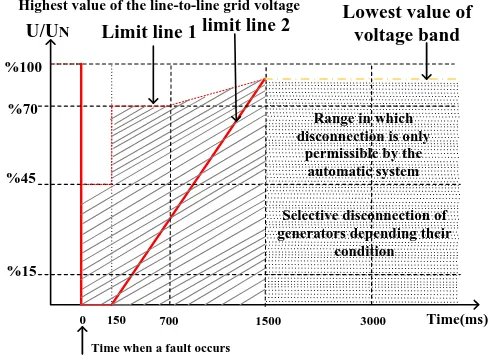
HE transient behavior of wind energy conversion systems (WECSs) during a fault condition is one of the significant problems [1-5] for power systems, at the level of high penetration of the WECSs. Most of the grid operators require that these WECSs should be capable of staying connected to the utility grid, as do the conventional power plants during the fault because, in this way, the secure and reliable operation of the power networks is guaranteed. This operational behavior is known as fault ride-through (FRT) capability [6, 7]. It is obvious that, for secure power system operation, the wind turbines should meet grid requirements. Among the different grid codes, “E.ON” grid code has the strongest FRT
requirements [6]. As shown in Fig. 1, according to the “E.ON”,
when the voltage at the point of common coupling (PCC) drops to a zero value for a timeframe of 0.15 seconds or fewer, the wind turbine must not be disconnected from the grid.
Simply, the WECSs are divided into fixed speed and variable
%100
%70
%45
%15
Time(ms)
0 150 700 1500 3000
U/UN Limit line 1 limit line 2
Lowest value of voltage band
Range in which disconnection is only
permissible by the automatic system
Selective disconnection of generators depending their
condition Highest value of the line-to-line grid voltage
[image:1.612.317.562.212.391.2]Time when a fault occurs
Fig. 1. Limits curve for the FRT requirement of the “E.ON” grid code.
speed [8, 9]. The most interesting one is the variable speed wind turbine (VSWT) due to the possibility of extracting more energy from a wind regime than from a fixed speed wind turbine (FSWT). Furthermore, enhanced power quality, low stress on the turbine and independent control of reactive and active powers are advantages of the VSWT [10, 11]. Nowadays, the large capacity of the VSWT is employed on the power network. But a large number of FSWTs has also been installed over the past decades and more will continue to be installed due to the low cost of installation and maintenance, as well as their reliable and robust characteristics [8, 12-14]. Furthermore, squirrel cage induction generators (SCIGs), as a WECS, are utilized to connect the FSWT directly to the grid.
The transient behavior of the SCIG during the faults is an important phenomenon which deserves special attention. The SCIG may accelerate to high speed during the short circuits, due to the abrupt reduction in the electrical torque. As a result, the reactive power consumed by the generator increases considerably, which is not compatible with the new grid codes [15]. So, special considerations are required to reduce the fault current and increase the FRT capability of the SCIG.
Accordingly, several studies were conducted on the FSWT fault current limitations to enable this type of WECS to stay connected with the grid during the fault. These methods include an energy storage system [16], a static synchronous compensator (STATCOM) [13, 17-19], a static synchronous
Seyed Behzad Naderi1, Student Member, IEEE, Michael Negnevitsky1, Senior Member, IEEE, Amin Jalilian2,
Mehrdad Tarafdar Hagh2, Senior Member, IEEE, Kashem M. Muttaqi3, Senior Member, IEEE
1School of Engineering and ICT, University of Tasmania, Hobart, TAS, Australia 2Faculty of Electrical and Computer Engineering, University of Tabriz, Tabriz, Iran
3School of Electrical, Computer and Telecommunications Engineering, University of Wollongong, NSW, Australia
Email: [email protected].
Optimum Resistive Type Fault Current Limiter: An Efficient Solution to
Achieve Maximum Fault Ride-through Capability of Fixed Speed Wind
Turbines during Symmetrical and Asymmetrical Grid Faults
series compensator (SSSC) [19], distributed constant power loads (CPLs) [8], a dynamic voltage restorer (DVR) [20], a series dynamic braking resistor (SDBR) [19, 21], a unified power quality conditioner (UPQC) [22, 23], capacitor banks [24], a static VAR compensator (SVC) [25] and a unified power flow controller (UPFC) [26].
Out of all the research mentioned above, in [8], [13], and [19], the authors used a STATCOM and distributed CPLs to achieve the maximum FRT capability of the FSWT. They have effective operation, especially in the case of asymmetrical faults. In [13], a STATCOM and coordinated positive and negative-sequence control, with the priority of the positive sequence, is applied to compensate for voltage dip during both symmetrical and asymmetrical faults. But this method requires more measurements and it is complicated. In a STATCOM, as a voltage source, self-turn on and turn off switches should be utilized. However, for a severe voltage dip, this method is not as effective [13, 19]. In [8], there are disadvantages similar to [13, 19], but the distributed CPLs need more ac/dc converters. Nonetheless, the CPLs inject a lower current to compensate for the voltage dip, in comparison with the aforementioned STATCOM.
In consideration of the techniques mentioned above, another common idea to reduce the fault current levels is fault current limiters (FCLs). In [27] and [28], different types of the FCLs are employed to enhance the FRT capability of the FSWT. The bridge type FCLs (BFCLs) have been utilized in [27, 28] to enhance the FRT of the FSWT during the fault. However, in [27] and [28] only fixed impedance has entered the FSWT fault current path. This procedure helps to limit the fault current. However, not only in this literature but in almost all studies, the most important issue has been omitted; in fact, the impact of the pre-fault conditions has not been considered in the FRT capability of the FSWT. It means that the fault location and the wind speed variations, which cause variable output active power, are not included in both analysis and simulation.
As mentioned above, in the literature, many methods and structures have been proposed to improve the FRT capability of the FSWT and decrease the high short-circuit current level during the fault. But, to the best knowledge of the authors of this paper, none of them guarantees the maximum FRT capability of the FSWT using fault current limiters (FCLs), considering the impact of the pre-fault conditions on the FRT.
For this purpose, an optimum resistive type fault current limiter (OR-FCL) is proposed in this paper, to achieve the maximum ride-through capability of the FSWT during symmetrical and asymmetrical grid faults. In this study, unlike previous work in [8], [17], [27, 28], the maximum FRT of the FSWT is obtained by the proposed OR-FCL, considering all the pre-fault situations. Both the fault location and the wind speed variations will be employed in analysis to produce an optimum resistance by the OR-FCL through the use of a special frequency and duty cycle. This technique ensures the maximum FRT capability of the FSWT after the symmetrical and asymmetrical fault occurrences. Finally, extensive simulations will be performed using PSCAD/EMTDC software for different operation conditions and various fault types, to show the
effectiveness of the OR-FCL in producing the maximum FRT of the FSWT.
II. INVESTIGATED SYSTEM
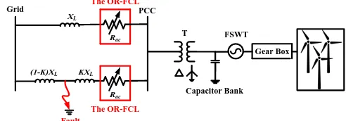
The investigated system includes a FSWT and the proposed OR-FCL. The FSWT is connected to the infinite bus through a double SCIG and the parallel transmission lines. Fig. 2 shows a single line diagram of the power system with the proposed OR-FCL in the beginning of each line. In Fig. 2, 𝑋𝐿 is the line reactance and the parameter of 𝑘 is used to represent the impact of the fault location on the FRT of the FSWT.
To model the FSWT, it is supposed that the wind turbine has a horizontal axis with three blades utilized to extract the power from the wind. In addition, the pitch control is applied to the wind turbine to protect it in high wind speeds above the rated speed.
Maximum extractable power from the wind can be expressed as follows [29]:
𝑃𝑤𝑖𝑛𝑑= (1 2⁄ )𝐶𝑝𝜌𝐴𝑉𝑤𝑖𝑛𝑑3 (1)
where 𝐶𝑝 and 𝐴 are the ratio of extractable power to the available power and the area swept by the blades, respectively. Also, the air density and the wind speed are shown by 𝜌 and
𝑉𝑤𝑖𝑛𝑑, respectively. In (1), 𝐶𝑝 is the function of blade pitch angle, 𝛽, and tip speed ratio, 𝜆 expressed in (2).
𝜆 = (𝜔𝑟𝑜𝑡𝑜𝑟. 𝑅𝑟𝑜𝑡𝑜𝑟) 𝑉⁄ 𝑤𝑖𝑛𝑑 (2)
that 𝜔𝑟𝑜𝑡𝑜𝑟 and 𝑅𝑟𝑜𝑡𝑜𝑟 are angular mechanical speed and rotor radius, respectively.
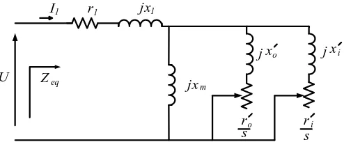
The single phase circuit model of the double SCIG is shown in Fig. 3. This type of induction generator has good efficiency under normal running conditions. In the double SCIG, the outer cage has a high resistance value and a low ratio of the reactance to the resistance; whereas the inner cage has low resistance value and a large ratio of the reactance to the resistance [30].
Resistances of the stator, and the inner and outer cages of the rotor are shown by 𝑟1, 𝑟𝑖′ and 𝑟𝑜′, respectively. In addition, 𝑋1,
𝑋𝑖′ and 𝑋𝑜′ refer to the leakage reactance of the stator, and the inner and outer cages of the rotor, respectively. Furthermore,
𝑋𝑚 is the magnetising reactance and U is the terminal voltage of the double SCIG. The stator current, which feeds the power system, is represented by 𝐼1. In addition, slip, s, is presented by
(𝑛𝑠− 𝑛𝑟) 𝑛⁄ 𝑠 whereby 𝑛𝑠 (𝑟. 𝑝. 𝑠) and 𝑛𝑟 (𝑟. 𝑝. 𝑠) are the synchronous speed and the rotor speed, respectively. The equivalent impedance from the stator point of view is shown by
𝑍𝑒𝑞 in Fig. 3.
Grid PCC
FSWT
Fault
Capacitor Bank Gear Box
Rac
KXL
(1-K)XL
XL
The OR-FCL
T Rac
[image:2.612.317.563.641.727.2]The OR-FCL
III. THE PROPOSED OR-FCL AND ITS OPERATION
PRINCIPLES
[image:3.612.329.576.50.152.2]Considering Fig. 2, each phase of the three phase line includes the proposed OR-FCL, which is represented by 𝑅𝑎𝑐. In Fig. 4, the single phase power circuit topology of the proposed OR-FCL is shown. As illustrated, the proposed OR-FCL is made of a single phase diode rectifier bridge, a resistance, 𝑅, placed in parallel with a self-turnoff switch and a small value of dc inductance, 𝐿𝑑𝑐.
The switching part has a main role in the fault current limiting characteristic. It is clear that the fault current will suddenly increase during the first moment of the fault. Therefore, to protect the self-turnoff switch against severe line current variations, 𝐿𝑑𝑐 is placed in series with the semiconductor switch.
In normal operation, the proposed OR-FCL has no effect on the power system. This is because the resistance 𝑅 is parallel with the self-turnoff switch. However, there are very low voltage drops on the diodes, the semiconductor switch and the
𝐿𝑑𝑐. Also, it should be mentioned that the value of the 𝐿𝑑𝑐 is small and its inherent resistance, 𝑟𝐿, can be neglected in most practical applications.
After occurrence of the fault (which can be symmetrical or asymmetrical), the current of the induction generator increases in the fault line. When this fault current reaches a pre-specified value, 𝐼0, at 𝑡0, the dedicated control circuit is applied to the proposed OR-FCL. In this way, the corresponding OR-FCL of the fault phase starts switching through the use of special frequency, 𝑓𝑠, and a duty cycle, 𝐷. With this switching pattern, the fault current is limited to a desired value. It is obvious that the peak of line current is equal to the dc current of 𝐿𝑑𝑐.
To calculate the limited line current by the proposed OR-FCL, Fig. 5 is used, which shows the line current of one of the phases for a three phase fault during the steady state. In nth switching period, when the self-turnoff switch is OFF from
𝑡2(𝑛−1) till 𝑡2(𝑛−1)+1, the differential equation of the current in the 𝐿𝑑𝑐 (𝑖𝑑𝑐) can be expressed as follows:
𝑅𝑂𝐹𝐹𝑖𝑑𝑐(𝑡) + 𝐿𝑑𝑐
𝑑𝑖𝑑𝑐
𝑑𝑡 = 𝑉𝐷𝐶 (3)
where, we have:
𝑉𝐷𝐶= 2𝑉𝑂𝑅−𝐹𝐶𝐿⁄ (4)𝜋
𝑅𝑂𝐹𝐹= 𝑟𝐿+ 𝑅 (5)
Meanwhile, 𝑉𝑂𝑅−𝐹𝐶𝐿 is the peak value of the ac voltage, which drops on the OR-FCL during the fault condition. With regard to Fig. 5 and initial value of 𝑖𝑑𝑐(𝑡 = 𝑡2(𝑛−1)) = 𝐼2(𝑛−1),
𝑖𝑑𝑐 can be expressed as follows:
𝑖𝑑𝑐(𝑡) =
𝑉𝐷𝐶
𝑅𝑂𝐹𝐹+ (𝐼2(𝑛−1)−
𝑉𝐷𝐶
𝑅𝑂𝐹𝐹
) 𝑒−𝑅𝑂𝐹𝐹𝐿𝑑𝑐(𝑡−𝑡2(𝑛−1)) (6)
U
r1 jx1
jxm
I1
ri
s Zeq
j xo
ro
s
j xi
Fig. 3. Single phase equivalent circuit of the double squirrel cage induction generator.
D1 D2
D3 D4
L
dcSelf-turnoff Switch
[image:3.612.372.502.194.316.2]R
Fig. 4. Single phase power circuit topology of the proposed OR-FCL.
Fig. 5. Steady state currents and the self-turnoff switching pulse during the fault condition.
By using (6), 𝐼2(𝑛−1)+1 at 𝑡2(𝑛−1)+1 can be written as follows:
𝐼2(𝑛−1)+1=
𝑉𝐷𝐶
𝑅𝑂𝐹𝐹+ (𝐼2(𝑛−1)−
𝑉𝐷𝐶
𝑅𝑂𝐹𝐹) 𝑒 −𝑅𝑂𝐹𝐹
𝐿𝑑𝑐(1−𝐷)𝑇𝑠 (7)
When the self-turnoff switch goes to ON state from 𝑡2(𝑛−1)+1 until 𝑡2𝑛, the same procedure can be utilized to calculate 𝐼2n at the end of ON state, in the nth switching period, 𝑡2𝑛. Therefore,
𝐼2𝑛 can be written as follow:
𝐼2𝑛=
𝑉𝐷𝐶
𝑅𝑂𝑁+ (𝐼2(𝑛−1)+1−
𝑉𝐷𝐶
𝑅𝑂𝑁) 𝑒 −𝑅𝑂𝑁
𝐿𝑑𝑐𝐷𝑇𝑠 (8)
where 𝑅𝑂𝑁 is 𝑟𝐿+ 𝑟𝑠𝑠, in which 𝑟𝑠𝑠 represents the ON resistance of the self-turnoff switch. As it is clear from Fig. 5, 𝐼2𝑛 is almost equal to 𝐼2(𝑛−1) during the steady state condition in the fault. Therefore, by employing (7) and (8), the value of 𝐼2n or the steady state level of the fault current, 𝐼𝑓, can be achieved as (9).
Time
C
u
rr
e
n
t
DC Reactor Current AC Phase Current Switching Pulse
(n-1)th nth I2(n-1) I2(n-1)+1 I2(n)
t2(n-1) t2(n)
[image:3.612.315.558.345.469.2]𝐼2𝑛= 𝐼𝑓
=
𝑉𝐷𝐶 𝑅𝑂𝑁+ (
𝑉𝐷𝐶 𝑅𝑂𝐹𝐹−
𝑉𝐷𝐶 𝑅𝑂𝐹𝐹𝑒
−𝑅𝑂𝐹𝐹
𝐿𝑑𝑐 (1−𝐷)𝑇𝑠−𝑉𝐷𝐶 𝑅𝑂𝑁) 𝑒
−𝑅𝑂𝑁 𝐿𝑑𝑐𝐷𝑇𝑠
1 − 𝑒−𝑅𝑂𝐹𝐹𝐿𝑑𝑐(1−𝐷)𝑇𝑠𝑒−𝑅𝑂𝑁𝐿𝑑𝑐𝐷𝑇𝑠
(9)
where 𝑇𝑠 equals to 1 𝑓⁄ 𝑠. If the 𝑓𝑠 is assumed to be a large value, then (9) can be simplified to (10). The values of 𝑟𝐿 and 𝑟𝑠𝑠 are very small compared with 𝑅, so, they can be ignored.
𝐼𝑓≅
𝑉𝐷𝐶
𝑅𝑂𝐹𝐹(1 − 𝐷) + 𝑅𝑂𝑁𝐷≅
𝑉𝐷𝐶
𝑅(1 − 𝐷) (10)
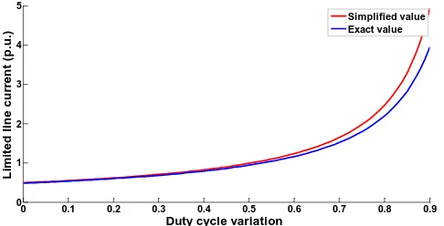
To compare the fault current level calculated in the simplified equation of (10) with the exact equation of (9), the fault current level limited by the proposed OR-FCL is plotted in terms of D for both, the exact equation, (9), and the simplified one, (10). As shown in Fig. 6, there is not a considerable difference between the exact and the simplified values.
Considering (10) and Fig. 6, it can be concluded that the value of 𝐼𝑓 depends on the duty cycle D. It means that by controlling D, it is possible to control the value of 𝐼𝑓 as well as the dc side resistance, 𝑅𝑑𝑐, expressed in (11).
𝑅𝑑𝑐= 𝑅(1 − 𝐷) (11)
After the fault removal, the proposed OR-FCL returns to the pre-fault condition and does not affect the normal operation of the grid.
Equations (10) and (11) prove that the duty cycle D of the switching pattern results in variable and controllable resistance by the proposed OR-FCL. So, to make the maximum FRT of FSWT in all pre-fault conditions and during all fault types, including symmetrical and asymmetrical faults, this controllable resistance can offer an optimum value to the power system during the fault. Through the next section, the calculation procedure of the optimum resistance to achieve the maximum FRT is obtained. Furthermore, it is shown that the optimum resistance value of the proposed OR-FCL depends on the pre-fault output active power of the FSWT and the fault location.
It is important to note that the ac side resistance value of the proposed OR-FCL, 𝑅𝑎𝑐, is different from the value of 𝑅𝑑𝑐. To calculate the relation between the values of 𝑅𝑎𝑐 and 𝑅𝑑𝑐, the active powers in the ac side, 𝑃𝑎𝑐, and the dc side, 𝑃𝑑𝑐, of the proposed OR-FCL are considered equal. However, it is supposed that the power losses of the diodes and the self-turnoff switch are not considerable. Therefore, we can write:
𝑃𝑎𝑐= 𝑃𝑑𝑐
= (𝑉𝑂𝑅−𝐹𝐶𝐿⁄√2)2⁄𝑅𝑎𝑐= (2𝑉𝑂𝑅−𝐹𝐶𝐿⁄ )𝜋 2⁄𝑅𝑑𝑐 (12)
As a result, the relation between the ac side resistance 𝑅𝑎𝑐 and the dc side resistance 𝑅𝑑𝑐 is expressed as follows:
[image:4.612.317.560.48.172.2]𝑅𝑑𝑐= (8 𝜋⁄ )𝑅2 𝑎𝑐 (13)
Fig. 6. The fault current level limited by the proposed OR-FCL for both the exact equation, (9), and the simplified one (10).
IV. UTILIZING THE PROPOSED OR-FCL TO OBTAIN
MAXIMUM FRT OF FSWT
To achieve the maximum FRT of the FSWT, two important pre-fault conditions need to be taken into account. The first one is the pre-fault active power and the second one is the fault location. Considering these two significant factors, during the fault, the proposed OR-FCL is able to create a situation in which the fault does not affect the induction generator. As a matter of fact, the output active power of the induction generator during the fault should be equal to the active power of the pre-fault condition. It is clear that the output active power of the induction generator is linked to the wind speed [7]. So, by utilizing a controllable resistance through the use of the proposed OR-FCL, a controllable active power consumption, with regard to the pre-fault conditions, can be achieved. This capability of the proposed OR-FCL guarantees the maximum FRT of the FSWT in all pre-fault conditions.
During the fault, the proposed OR-FCL is expected to consume the excess energy of the fault. But the amount of the consumed excess active power determines how the FSWT can ride through the fault. During the fault, the consumed active power of the proposed OR-FCL (𝑃𝑂𝑅−𝐹𝐶𝐿) in each fault phase can be expressed as follows:
𝑃𝑂𝑅−𝐹𝐶𝐿= 𝑉𝑂𝑅−𝐹𝐶𝐿2 ⁄𝑅𝑎𝑐 (14)
Considering Fig. 2, 𝑉𝑂𝑅−𝐹𝐶𝐿 is equal to
𝑉𝑃𝐶𝐶(𝑅𝑎𝑐⁄√𝑅𝑎𝑐2 + 𝑘2𝑋𝐿2), where 𝑉𝑃𝐶𝐶 is the line to phase voltage (RMS value) of the PCC and k is the ratio of the fault distance to the parallel line length. Due to limiting the fault current by the OR-FCL, the value of 𝑉𝑃𝐶𝐶 during the fault is almost the post-fault value. The concept of voltage sag compensation has been proposed in [4], which shows that the fault current limiting characteristic of the FCLs could maintain the PCC voltage at an acceptable range. In the next section, the simulation results will also prove this concept.
Considering (14), to get the maximum FRT of the FSWT, the proposed OR-FCL should consume the pre-fault active power of the fault phase by inserting the optimum resistance value, 𝑅𝑎𝑐,𝑜𝑝𝑡.. This statement can be expressed as below:
𝑉𝑃𝐶𝐶2 𝑅𝑎𝑐,𝑜𝑝𝑡.⁄(𝑅𝑎𝑐,𝑜𝑝𝑡.2 + 𝑘2𝑋𝐿2)= 𝑃𝑃𝑟𝑒−𝐹𝑎𝑢𝑙𝑡,𝑃ℎ𝑎𝑠𝑒 (15)
0 0.1 0.2 0.3 0.4 0.5 0.6 0.7 0.8 0.9
0 1 2 3 4 5
Duty cycle variation
L
im
it
e
d
l
in
e
c
u
rr
e
n
t (
p
.u
.)
[image:4.612.48.299.60.120.2]where 𝑋𝐿 is the reactance of each phase and 𝑃𝑃𝑟𝑒−𝐹𝑎𝑢𝑙𝑡,𝑃ℎ𝑎𝑠𝑒 is transferred active power in each phase. Due to the same characteristics of the parallel lines, 𝑃𝑃𝑟𝑒−𝐹𝑎𝑢𝑙𝑡,𝑃ℎ𝑎𝑠𝑒 is the same in all phases. So, if the generated active power of the FSWT is represented by 𝑃𝐺, then 𝑃𝑃𝑟𝑒−𝐹𝑎𝑢𝑙𝑡,𝑃ℎ𝑎𝑠𝑒 will be equal to 𝑃𝐺⁄6. Using (15) to compute 𝑅𝑎𝑐,𝑜𝑝𝑡. leads to the following expression:
𝑅𝑎𝑐,𝑜𝑝𝑡.=
(𝑉𝑃𝐶𝐶2 + √𝑉𝑃𝐶𝐶4 − 4𝑃𝑃𝑟𝑒−𝐹𝑎𝑢𝑙𝑡,𝑃ℎ𝑎𝑠𝑒2 𝑘2𝑋𝐿2) (2𝑃⁄ 𝑃𝑟𝑒−𝐹𝑎𝑢𝑙𝑡,𝑃ℎ𝑎𝑠𝑒)
= (3𝑉𝑃𝐶𝐶2 + √9𝑉
𝑃𝐶𝐶4 − 𝑃𝐺2𝑘2𝑋𝐿2) 𝑃⁄ 𝐺 (16)
At this stage, by using (11), (13) and (16), the optimum value of D can be calculated, based on the value of 𝑅𝑎𝑐,𝑜𝑝𝑡. as follows:
𝐷𝑜𝑝𝑡.= 1 − (24𝑉𝑃𝐶𝐶2 + 8√9𝑉𝑃𝐶𝐶4 − 𝑃𝐺2𝑘2𝑋𝐿2) (𝜋⁄ 2𝑅𝑃𝐺) (17)
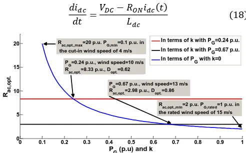
Now, to show the impact of the fault conditions (the pre-fault active power and the pre-fault location), (16) and (17) are employed. It is clear that 𝑅𝑎𝑐,𝑜𝑝𝑡. depends on 𝑃𝐺 and 𝑘. Therefore, the variation of 𝑅𝑎𝑐,𝑜𝑝𝑡. is plotted in terms of 𝑘 and
𝑃𝐺 in Fig. 7. In Fig. 7, 𝑅𝑎𝑐,𝑜𝑝𝑡. and 𝐷𝑜𝑝𝑡. are calculated for two wind speeds, considering the simulation parameters.
As shown in Fig. 7, the variation of 𝑅𝑎𝑐,𝑜𝑝𝑡. is plotted with respect to 𝑘 for two values of 𝑃𝐺. These two different values for
𝑃𝐺 prove that each one requires its own optimum resistance value to get the maximum fault ride-through capability of the FSWT. So, the pre-fault conditions are important from the point of view of maximum FRT.
The other fact, which can be concluded from Fig. 7, is linked to the slope of curves plotted in terms of k. As is clear, the slope of curves is almost zero when the fault location changes in the parallel line. It means that 𝑅𝑎𝑐,𝑜𝑝𝑡. is approximately independent from the fault location. As a result, the fault location is considered constant throughout the simulation and its location in the beginning of the parallel line (𝑘 = 0) is found as a worst case of the fault situation.
Furthermore in Fig. 7, the variation of 𝑅𝑎𝑐,𝑜𝑝𝑡. is plotted in respect of 𝑃𝐺 for 𝑘 = 0. It is shown that 𝑅𝑎𝑐,𝑜𝑝𝑡. changes in a wide range with respect to the variation of 𝑃𝐺 (0.1 to 1p.u.). As is clear, 𝑃𝐺 does not have constant value due to the wind speed variation [7]. Consequently, to achieve the maximum FRT of the FSWT in all pre-fault situations and during various grid faults, the proposed OR-FCL is found to be promising.
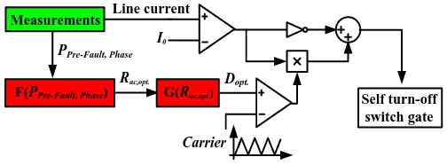
The dedicated control circuit of the proposed OR-FCL is shown in Fig. 8. 𝑃𝑃𝑟𝑒−𝐹𝑎𝑢𝑙𝑡,𝑃ℎ𝑎𝑠𝑒 and the line currents are measured continually. F(𝑃𝑃𝑟𝑒−𝐹𝑎𝑢𝑙𝑡,𝑃ℎ𝑎𝑠𝑒) represents (16), which is utilized to calculate 𝑅𝑎𝑐,𝑜𝑝𝑡.. The output of F(𝑃𝑃𝑟𝑒−𝐹𝑎𝑢𝑙𝑡,𝑃ℎ𝑎𝑠𝑒) is used as an input for G(𝑅𝑎𝑐,𝑜𝑝𝑡.) that expresses (17). Finally, the output of G(𝑅𝑎𝑐,𝑜𝑝𝑡.) as 𝐷𝑜𝑝𝑡. is calculated and utilized for the self-turnoff switching pattern. So, if any type of the grid fault occurs, the proposed OR-FCL is
ready to insert the optimum value of the resistance 𝑅𝑎𝑐,𝑜𝑝𝑡. to achieve the maximum FRT of the FSWT during the fault.
In the dedicated control circuit, a current transformer (CT) and a potential transformer (PT) are utilized. Regarding the fault current level, the ratio of the CT is obtained to avoid saturation and inaccuracy. To measure the output active power of the FSWT 𝑃𝐺, PT is used with CT. The ratio of PT is provided based on the output voltage of the FSWT.
Before the fault, 𝑅𝑎𝑐,𝑜𝑝𝑡. and 𝐷𝑜𝑝𝑡. are calculated in terms of
𝑃𝐺 considering (16) and (17), respectively. In fact, as soon as the fault is detected, the switching pattern will be applied to the semiconductor switch without any delay. Possible delays could occur in the fault detection process, which includes delays in the electronic components of the control circuit. To compute the delay of electronic components in the control circuit from input to output, typical delays in comparator, NOT/AND and OR are added. The cumulative delay of the electronic components is less than 0.5 ms. Meanwhile after fault detection, there is a turnoff delay in the semiconductor switch. The possible delay in the high power semiconductor switch, considering the voltage and current ratings of the investigated system and type of the semiconductor switch, is less than 1 ms. As is clear, the total delay will not affect the operation of the proposed controller to a significant degree. This is because not only is the total delay a small percentage of the power system frequency, but also because 𝐿𝑑𝑐 will restrict the fault current level before the semiconductor switch operation.
V. DESIGN CONSIDERATIONS
In the design of the control circuit, some issues, which are linked to the value of 𝐿𝑑𝑐 and R, need to be taken into account and are discussed below.
A. The value of 𝐿𝑑𝑐
After the fault occurrence, 𝑖𝑑𝑐 suddenly increases, before the self-turnoff switch operation. As mentioned, 𝐿𝑑𝑐 is employed to protect the self-turnoff switch in the first moments of the fault. Therefore, its value should be selected in such a way that the rate of current change in the self-turnoff switch becomes lower than its 𝑑𝑖𝑚𝑎𝑥⁄𝑑𝑡.
Before the self-turnoff switch operation, rate of change of
𝑖𝑑𝑐 is expressed as follows:
𝑑𝑖𝑑𝑐
𝑑𝑡 =
𝑉𝐷𝐶− 𝑅𝑂𝑁𝑖𝑑𝑐(𝑡)
[image:5.612.47.304.147.213.2] [image:5.612.316.562.570.723.2]𝐿𝑑𝑐 (18)
Fig. 7. Optimum resistance variation, 𝑅𝑎𝑐,𝑜𝑝𝑡., with respect to 𝑃𝐺 and k.
0 0.1 0.2 0.3 0.4 0.5 0.6 0.7 0.8 0.9 1
0 5 10 15 20
P
G (p.u) and k
Ra
c
,o
p
t.
In terms of k with PG=0.24 p.u. In terms of k with PG=0.67 p.u. In terms of PG with k=0
Rac,opt.,min=2 p.u. PG,rated=1 p.u. in the rated wind speed of 15 m/s Rac,opt.,max=20 p.u. PG,min=0.1 p.u. in
the cut-in wind speed of 4 m/s P
G=0.24 p.u., wind speed=10 m/s
Rac,opt.=8.33 p.u., Dopt.=0.62
P
G=0.67 p.u., wind speed=13 m/s
Self turn-off switch gate Line current
I0
Carrier Dopt.
Measurements
PPre-Fault, Phase
F(PPre-Fault, Phase)
Rac,opt.
[image:6.612.48.300.51.144.2]G(Rac,opt.)
Fig. 8. Dedicated control circuit of the proposed OR-FCL.
Due to the high rate of current change at the first moment of the fault, the value of 𝑖𝑑𝑐 is considered the pre-fault current in
𝐿𝑑𝑐, 𝐼𝑝𝑟𝑒−𝑓𝑎𝑢𝑙𝑡, which is equal to the peak of the line current. So, the value of 𝐿𝑑𝑐 can be achieved as follows:
𝐿𝑑𝑐>
𝑉𝐷𝐶− 𝑅𝑂𝑁𝐼𝑝𝑟𝑒−𝑓𝑎𝑢𝑙𝑡
𝑑𝑖𝑚𝑎𝑥⁄𝑑𝑡 (19)
B. The value of R
As discussed, R including the self-turnoff switch is the most important part of the proposed OR-FCL in limiting the fault current to the desired value. It is mentioned that, to attain the maximum FRT of the FSWT during the fault, the proposed OR-FCL in each phase should consume 𝑃𝐺⁄6. If 𝑃𝐺 changes between 𝑃𝐺,𝑚𝑖𝑛 to 𝑃𝐺,𝑟𝑎𝑡𝑒𝑑 (as shown in Fig. 7), the extracted active power in the cut-in wind speed and the rated wind speed, respectively [31], 𝑅𝑎𝑐,𝑜𝑝𝑡. should be attained by the duty cycle variation for the special value of R, for all generated active power variation.
Considering (16) for 𝑃𝑔,𝑚𝑖𝑛 at the cut-in wind speed,
𝑅𝑎𝑐,𝑜𝑝𝑡.,𝑚𝑎𝑥 can be achieved as follows:
𝑅𝑎𝑐,𝑜𝑝𝑡.,𝑚𝑎𝑥= (3𝑉𝑃𝐶𝐶2 + √9𝑉𝑃𝐶𝐶4 − 𝑃𝑔,𝑚𝑖𝑛2 𝑘2𝑋𝐿2) 𝑃⁄ 𝑔,𝑚𝑖𝑛 (20)
Therefore, by employing (13) and (20), 𝑅𝑚𝑎𝑥 in the proposed OR-FCL is calculated in (21) for the 𝑃𝑔,𝑚𝑖𝑛 at the cut-in wcut-ind speed.
𝑅𝑚𝑎𝑥 = (8 𝜋⁄ )𝑅2 𝑎𝑐,𝑜𝑝𝑡.,𝑚𝑎𝑥 (21)
It is clear from (21), the value of 𝑅𝑚𝑎𝑥 is required to have the maximum FRT of the FSWT in all conditions of the pre-fault. So, the minimum value for R should be higher than 𝑅𝑚𝑎𝑥. Any required value of the optimum resistance for the different wind speeds (higher than the cut-in wind speed) can be achieved through the duty cycle variation. In this condition, it is guaranteed that the FSWT has the maximum FRT capability for all wind speed variations, from the cut-in wind speed to the rated wind speed. Regarding Fig. 7, in the cut-in wind speed, 4
m/s, 𝑃𝐺,𝑚𝑖𝑛 is supposed to be 0.1 p.u. that needs 𝑅𝑎𝑐,𝑜𝑝𝑡.,𝑚𝑎𝑥 of 20 p.u. to get the maximum FRT capability in the FSWT. As a result, considering (21), 𝑅𝑚𝑎𝑥 will be 16.21 p.u. In the simulation section, R of 18 p.u. is selected for the test study power system, which is higher than 𝑅𝑚𝑎𝑥.
VI. SIMULATION RESULTS AND DISCUSSIONS
To demonstrate the effectiveness of the proposed OR-FCL, different asymmetrical and symmetrical grid faults are applied to the system presented in Fig. 2. The following three case studies are carried out:
Case I) Asymmetrical Fault: line to ground in A phase (LG).
Case II) Asymmetrical Fault: double line to ground in A and B
phases (LLG).
Case III) Symmetrical Fault: three phase to ground (LLLG).
Also, in each case, two values are considered for wind speed; these are 10 m/s and 13 m/s. In this way, the optimum resistance value for each wind speed will be applied to show how the value of 𝑅𝑎𝑐,𝑜𝑝𝑡. effectively achieves the maximum FRT of the FSWT. Considering Fig. 7, the optimum resistance value in the ac side, as well as the optimum duty cycle, have been calculated. It is clear that the optimum resistance value depends on the pre-fault conditions and the fault type does not affect its value.
PSCAD/EMTDC software is utilized for the simulation. Table I presents the parameters of all the components of the investigated system. To validate the effectiveness of the proposed OR-FCL, its performance is investigated against “E.ON” grid code requirement. So, in all case studies, the fault
continues for 0.15 seconds and it occurs in the beginning of one of the parallel lines at t=10 s. When the fault current in the fault phase reaches 𝐼0= 1.1 𝑝. 𝑢., the proposed OR-FCL operates and limits the fault current through the use of a special frequency and the duty cycle. The value of 𝐼0 is adjusted, considering the maximum permissible fault current level in the power system. Regarding the applicability of the proposed OR-FCL to repetitive faults, two transient single phase faults in case I are applied to the investigated system in the beginning of one of the parallel lines at 10 s and 10.5 s for 0.15 seconds.
TABLE I. SIMULATION PARAMETERS
Wind Turbine
MOD 2 in PSCAD/EMTDC software for the horizontal axis, three blades;
Rated angular mechanical speed: 1000rpm; Rotor Radius: 40m, Air density: 1.229kg/m^3
Gear box efficiency: 0.9,
Capacitor bank, star connection: 690 V, 300 kVAR
Power factor in rated wind speed: 0.9 Rated wind speed: 15 m/s
Cut-in wind speed: 4 m/s
Squirrel Cage Induction Generator
2 MVA,690 V
Stator resistance: 0.066p.u. Outer cage resistance: 0.298p.u. Inner cage resistance: 0.018p.u. Stator leakage reactance: 0.046p.u. Magnetising reactance: 3.86p.u. Outer cage reactance: 0.122p.u. Inner cage reactance: 0.105p.u.
Polar moment of inertia: 5s, Mecanical damping: 0.008p.u. Transformer
2 MVA, 690 V/13.8 kV Parallel Lines 𝑋
𝐿: 0.0419p.u., The proposed
OR-FCL
𝑅 = 18 𝑝. 𝑢., 𝐿𝑑= 0.01 𝐻
Voltage drop on diodes=3V
Voltage drop on the self-turnoff switch =3V
Case I: Asymmetrical LG Fault
At first, the results are presented for the wind speed of
13 𝑚 𝑠⁄ during an LG fault at the PCC. To validate the analysis, in addition to 𝐷𝑜𝑝𝑡. for 𝑅𝑎𝑐,𝑜𝑝𝑡 to get the maximum FRT of the FSWT, different values of the duty cycle, lower and higher than 𝐷𝑜𝑝𝑡., are also considered to show how other values of D, and consequently 𝑅𝑎𝑐, negatively affect the FRT capability of the FSWT. Fig. 9 shows the impedance of the proposed OR-FCL 𝑅𝑎𝑐 for different values of the duty cycle during the fault. As is clear, different values of the duty cycle in the proposed OR-FCL generate different values of the impedance. The enlarged view shows the step-by-step increase of the impedance based on the switching pattern of the semiconductor switch in the first moments of the fault. Considering (11) and (13), the impedance value 𝑅𝑎𝑐 increases until it reaches (1 − 𝐷)𝑅𝜋2⁄8. Fig. 10 shows the rotor speed with and without the proposed OR-FCL. As evident, for the value of 𝑅𝑎𝑐,𝑜𝑝𝑡. of the proposed OR-FCL, the rotor speed variations decrease to the minimum level. As a matter of fact, the FSWT can ride through the fault in the best manner.
[image:7.612.317.560.58.181.2] [image:7.612.319.559.219.342.2]The fault current value and the PCC voltage are presented in Fig. 11 and Fig. 12. As shown in Fig. 11, the fault current level for the optimum resistance value remains in the pre-fault condition. It means that the proposed OR-FCL consumes almost all the pre-fault active power of the fault phase (Fig. 13) and the fault does not have any considerable effect on the operation of the FSWT. Considering Fig. 12, the proposed OR-FCL keeps the PCC voltage in an acceptable range by 𝑅𝑎𝑐,𝑜𝑝𝑡. The voltage sag compensation concept of the fault current limiters is discussed in [4].
Fig. 9. The generated impedance of the proposed OR-FCL for the wind speed of 13 m/s during the LG fault.
Fig. 10. The rotor speed for the wind speed of 13 m/s during the LG fault.
[image:7.612.318.558.379.504.2]Fig. 11. The fault phase current, A phase, for the wind speed of 13 m/s during the LG fault.
Fig. 12. The PCC voltage, A phase, for the wind speed of 13 m/s during the LG fault.
Fig. 13. The output active power of the FSWT for the wind speed of 13 m/s
during the LG fault.
With regard to the applicability of the proposed OR-FCL to repetitive faults, two transient LG faults are applied in the beginning of one of the parallel lines at 10 s and 10.5 s for 0.15 seconds. The generated impedance is shown in Fig. 14. As is obvious, after the first fault removal, the impedance of the OR-FCL quickly becomes zero. So, the proposed OR-OR-FCL gets ready for the next fault. The rotor speed is presented in Fig. 15. Due to minimum rotor speed oscillations for 𝐷𝑜𝑝𝑡., as soon the removal of the first fault occurs, the rotor speed reruns to its normal condition. The fault phase current and the output active power of the FSWT are shown in Fig. 16 and 17, respectively. As is expected, minimum oscillations are related to the optimum value of the resistance.
9 9.5 10 10.5 11 11.5 12
0 5 10 15
Time (s)
Im
p
e
d
a
n
c
e
(
p
.u
.)
D=0.95 D=0.35 Dopt.=0.86
10 10.01 10.02 10.03
0 1 2 3 4
Enlarged view
9 9.5 10 10.5 11 11.5 12
1.016 1.017 1.018 1.019 1.02 1.021 1.022 1.023 1.024
Time (s)
R
o
to
r S
p
e
e
d
(
p
.u
.)
Without FCL D=0.95 D=0.35 Dopt.=0.86
9 9.5 10 10.5 11 11.5 12
0.4 0.6 0.8 1 1.2 1.4 1.6 1.8
Time (s)
C
u
rr
e
n
t (
p
.u
.)
Without FCL D=0.95 D=0.35 Dopt.=0.86
9 9.5 10 10.5 11 11.5 12
0 0.2 0.4 0.6 0.8 1 1.2 1.4 1.6
Time (s)
V
o
lt
a
g
e
(
p
.u
.)
Without FCL D=0.95 D=0.35 Dopt.=0.86
9 9.5 10 10.5 11 11.5 12
0.4 0.5 0.6 0.7 0.8 0.9 1
Time (s)
A
c
tiv
e
P
o
we
r (
p
.u
.)
[image:7.612.51.301.434.561.2] [image:7.612.51.299.593.717.2]Fig. 14. The generated impedance of the proposed OR-FCL for the wind speed of 13 m/s during repetitive transient LG faults.
[image:8.612.313.563.297.416.2]Fig. 15. The rotor speed for the wind speed of 13 m/s during repetitive transient LG faults.
Fig. 16. The fault phase current, A phase, for the wind speed of 13 m/s during repetitive transient LG faults.
Fig. 17. The output active power of the FSWT for the wind speed of 13 m/s
during repetitive transient LG faults.
As aforementioned, in practical conditions, the wind speed is variable. Therefore, 𝑃𝐺 cannot be assumed to be constant, considering the wind speed variation [7]. So, it is supposed that the wind speed is changed from 13 𝑚/𝑠 to 10 𝑚/𝑠. In this situation, 𝑃𝐺 is also changed from 0.67 𝑝. 𝑢. to 0.24 𝑝. 𝑢.
Considering Fig. 7, to achieve the maximum FRT of the FSWT,
𝐷𝑜𝑝𝑡. should be changed from 86 % for the wind speed of
13 𝑚/𝑠 to 62 % for the wind speed of 10 𝑚/𝑠.
Fig. 18 presents the impedance of the proposed OR-FCL for
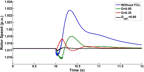
𝐷𝑜𝑝𝑡.= 62 % and 𝐷 = 86 %. The rotor speed of the FSWT in the wind speed of 10 m/s is shown in Fig. 19 during the LG fault. The rotor speed variations for 𝐷𝑜𝑝𝑡.= 62 % is lower than
𝐷 = 86 %. It means that, if the resistance value of the OR-FCL remains constant for all 𝑃𝐺, it cannot guarantee the maximum FRT of the FSWT.
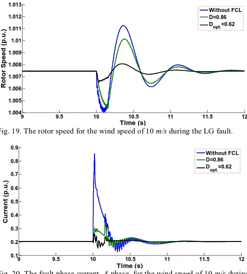
Furthermore, the fault current level of the fault phase is illustrated in Fig. 20. For the optimum resistance value, the current level is kept almost in the pre-fault condition.
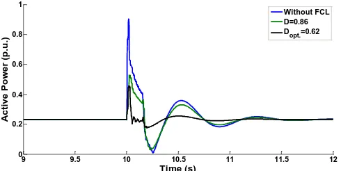
In addition, the output active power of the FSWT is shown in Fig. 21. It is clear that, when the optimum resistance value is calculated, considering the pre-fault conditions, the low disturbances appear on the output active power of the induction generator after the fault removal. So, the wind turbine can remain connected, as it is operated with the maximum FRT during the fault, with the aid of the OR-FCL.
[image:8.612.50.299.364.489.2]Fig. 18. The generated impedance of the proposed OR-FCL for the wind speed of 10 m/s during the LG fault.
[image:8.612.315.562.450.724.2]Fig. 19. The rotor speed for the wind speed of 10 m/s during the LG fault.
Fig. 20. The fault phase current, A phase, for the wind speed of 10 m/s during the LG fault.
9 9.5 10 10.5 11 11.5 12
0 5 10 15 Time (s) Im p e d a n c e ( p .u .) D=0.95 D=0.35 Dopt.=0.86
9 9.5 10 10.5 11 11.5 12
1.014 1.016 1.018 1.02 1.022 1.024 1.026 1.028 Time (s) R o to r S p e e d ( p .u .) Without FCL D=0.95 D=0.35 Dopt.=0.86
9 9.5 10 10.5 11 11.5 12
0.4 0.6 0.8 1 1.2 1.4 1.6 1.8 1.8 Time (s) C u rr e n t ( p .u .) Without FCL D=0.95 D=0.35 Dopt.=0.86
9 9.5 10 10.5 11 11.5 12
0.4 0.5 0.6 0.7 0.8 0.9 1 Time (s) A c tiv e P o we r ( p .u .) Without FCL D=0.95 D=0.35 Dopt.=0.86
9 9.5 10 10.5 11 11.5 12
0 2 4 6 8 10 Time (s) Im p e d a n c e ( p .u .) D=0.86 Dopt.=0.62
10 10.01 10.02 10.03
0 1 2 3 4 Enlarged view
9 9.5 10 10.5 11 11.5 12
1.004 1.005 1.006 1.007 1.008 1.009 1.01 1.011 1.012 1.013 Time (s) R o to r S p e e d ( p .u .) Without FCL D=0.86 Dopt.=0.62
9 9.5 10 10.5 11 11.5 12
[image:8.612.50.298.521.645.2]Fig. 21. The output active power of the FSWT for the wind speed of 10 m/s
during the LG fault.
A. Asymmetrical LLG fault
[image:9.612.53.298.48.171.2]In this asymmetrical fault type, the LLG fault is applied at the beginning of the parallel line. Due to the fault condition being worse than the LG fault, the FSWT is unstable without the OR-FCL, after the fault removal. To avoid an excess of figures, only the rotor speed is shown as one of the key parameters. Fig. 22 shows the rotor speed for a wind speed of 13 𝑚 𝑠⁄ . Considering Fig. 22, the optimum resistance value can ensure the maximum FRT of the FSWT during the LLG fault. In fact, the rotor speed variation for the optimum resistance is the lowest one.
[image:9.612.315.560.327.454.2]Also, for a wind speed of 10 𝑚 𝑠⁄ , the rotor speed variation is shown in Fig. 23. This figure proves that when wind speed is changed, the optimum resistance value should be calculated and inserted for the new condition to obtain the maximum FRT of the FSWT. In addition, considering Fig. 23, without using the proposed OR-FCL, the FSWT remains stable due to low output active power in the wind speed of 10 𝑚 𝑠⁄ .
[image:9.612.48.298.422.549.2]Fig. 22. The rotor speed for the wind speed of 13 m/s during the LLG fault.
Fig. 23. The rotor speed for the wind speed of 10 m/s during the LLG fault.
B. Symmetrical LLLG fault
In this section, the worst fault condition, a three phase fault is applied to the investigated system. Two wind speeds, as used in the previous fault studies, are considered in order to evaluate the operation of the proposed OR-FCL.
For a wind speed of 13 𝑚 𝑠⁄ , the rotor speed is presented in Fig. 24. Similar to the previous figures, which show the rotor speed for the different fault types, the minimum oscillation is related to the optimum resistance value. Also, it is clear that because of the worst fault condition, the FSWT becomes unstable after the fault without any FRT capability.
Finally, for a wind speed of 10 𝑚 𝑠⁄ , the rotor speed for the LLLG fault is shown in Fig. 25. This figure also proves that the optimum resistance value of the proposed OR-FCL has the main effect on the FRT of the FSWT. In fact, by using 𝑅𝑎𝑐,𝑜𝑝𝑡. considering the pre-fault conditions, the OR-FCL is able to obtain the maximum FRT of the FSWT during the fault.
[image:9.612.317.560.481.605.2]The results prove that the consumed active power by the OR-FCL has the same value of the pre-fault conditions during wind speed variations. Also, the rotor speed oscillations, caused by the fault, have the lowest oscillations when 𝑅𝑎𝑐,𝑜𝑝𝑡. is employed to the fault phase by the OR-FCL.
Fig. 24. The rotor speed for the wind speed of 13 m/s during the LLLG fault.
Fig. 25. The rotor speed for the wind speed of 10 m/s during the LLLG fault.
VII. CONCLUSION
This paper has proposed an optimum resistive type FCL (OR-FCL) to improve the fault ride-through capability of the FSWT during symmetrical and asymmetrical grid faults. A dedicated control circuit is also designed for the proposed OR-FCL. As shown, by means of this control circuit, the OR-FCL calculates an optimum resistance value (𝑅𝑎𝑐,𝑜𝑝𝑡.) with respect to all pre-fault operation conditions, including the fault location
9 9.5 10 10.5 11 11.5 12
0 0.2 0.4 0.6 0.8 1
Time (s)
A
c
tiv
e
P
o
we
r (
p
.u
.)
Without FCL D=0.86 Dopt.=0.62
9 9.5 10 10.5 11 11.5 12
1.01 1.015 1.02 1.025 1.03 1.035
Time (s)
R
o
to
r S
p
e
e
d
(
p
.u
)
Without FCL D=0.95 D=0.35 Dopt.=0.86
9 9.5 10 10.5 11 11.5 12
0.99 0.995 1 1.005 1.01 1.015 1.02 1.025
Time (s)
R
o
to
r S
p
e
e
d
(
p
.u
.)
Without FCL D=0.86 Dopt.=0.62
9 9.5 10 10.5 11 11.5 12
1 1.02 1.04 1.06 1.08 1.1
Time (s)
R
o
to
r S
p
e
e
d
(
p
.u
.)
Without FCL D=0.95 D=0.35 Dopt.=0.86
9 9.5 10 10.5 11 11.5 12
0.98 0.985 0.99 0.995 1 1.005 1.01 1.015 1.02 1.025
Time (s)
R
o
to
r S
p
e
e
d
(
p
.u
.)
[image:9.612.51.299.575.702.2](k) and the pre-fault output active power (𝑃𝐺) of the induction generator. The calculated value of 𝑅𝑎𝑐,𝑜𝑝𝑡. enters the fault current path through the use of the special switching pattern with the frequency of 𝑓𝑠 and the duty cycle of 𝐷𝑜𝑝𝑡.. In this way, the proposed OR-FCL limits the fault current efficiently and guarantees the maximum FRT capability of the FSWT during various grid faults. It has been also shown that the transient behaviour of the FSWT has been improved, especially during the worst cases of the fault condition, thanks to the proposed OR-FCL. Design consideration has been discussed to calculate the value of the dc reactor of the OR-FCL 𝐿𝑑𝑐 and the value of resistance R parallel with the self-turnoff switch. Therefore, the OR-FCL guarantees, that for all wind speed variations, 𝑅𝑎𝑐,𝑜𝑝𝑡. is achieved by the special switching pattern and is ready to enter the fault phase.
VIII. REFERENCES
[1] X. Wang, X. Wei, and Y. Meng, "Experiment on Grid-Connection Process of Wind Turbines in Fractional Frequency Wind Power System," IEEE Trans. Energy Convers., vol. 30, no. 3, pp. 22-31, Mar. 2015.
[2] M. H. Zamani, S. H. Fathi, G. Riahy, M. Abedi, and N. Abdolghani, "Improving transient stability of grid-connected squirrel-cage induction generators by plugging mode operation," IEEE Trans. Energy Convers.,
vol. 27, no. 3, pp. 707-714, Mar. 2012.
[3] D. H. Nguyen and M. Negnevitsky, "A review of fault ride through strategies for different wind turbine systems," in Australasian Uni. Power Eng. Conf. (AUPEC), 2010, pp. 1-5.
[4] M. Jafari, S. Naderi, M. Hagh, M. Abapour, and S. Hosseini, "Voltage sag compensation of point of common coupling (PCC) using fault current limiter," IEEE Trans. Power Del., vol. 26, no. 4, pp. 2638-2646, Apr. 2011.
[5] C. E. Ugalde-Loo, J. B. Ekanayake, and N. Jenkins, "State-Space Modeling of Wind Turbine Generators for Power System Studies," IEEE Trans. Ind. Appl., vol. 49, no. 1, pp. 223-232, Jan./Feb. 2013.
[6] M. Tsili and S. Papathanassiou, "A review of grid code technical requirements for wind farms," IET Renew. Power Gen., vol. 3, no. 3, pp. 308-332, Mar. 2009.
[7] C. Chompoo-inwai, C. Yingvivatanapong, K. Methaprayoon, and L. Wei-Jen, "Reactive compensation techniques to improve the ride-through capability of wind turbine during disturbance," IEEE Trans. Ind. Appl.,
vol. 41, no. 3, pp. 666-672, May/Jun. 2005.
[8] N. Jelani and M. Molinas, "Asymmetrical Fault Ride Through as Ancillary Service by Constant Power Loads in Grid-Connected Wind Farm," IEEE Trans. Power Electron., vol. 30, no. 3, pp. 1704-1713, Mar. 2015. [9] Y. Zou, M. E. Elbuluk, and Y. Sozer, "Simulation Comparisons and
Implementation of Induction Generator Wind Power Systems," IEEE Trans. Ind. Appl., vol. 49, no. 3, pp. 1119-1128, May/Jun. 2013. [10] S. Alaraifi, A. Moawwad, M. S. El Moursi, and V. Khadkikar, "Voltage
Booster Schemes for Fault Ride-Through Enhancement of Variable Speed Wind Turbines," IEEE Trans. Sustain. Energy, vol. 4, no. 4, pp. 1071-1081, Apr. 2013.
[11] N. K. S. Naidu and B. Singh, "Experimental Implementation of Doubly Fed Induction Generator Based Standalone Wind Energy Conversion System," IEEE Trans. Ind. Appl., vol. 52, no. 4, pp. 3332-3339, Jul./Aug. 2016.
[12] M. H. Ali and W. Bin, "Comparison of Stabilization Methods for Fixed-Speed Wind Generator Systems," IEEE Trans. Power Del., vol. 25, no. 1, pp. 323-331, 2010.
[13] C. Wessels, N. Hoffmann, M. Molinas, and F. W. Fuchs, "StatCom control at wind farms with fixed-speed induction generators under asymmetrical grid faults," IEEE Trans. Ind. Electron., vol. 60, no. 7, pp. 2864-2873, Jul. 2013.
[14] T. Ahmed, O. Noro, E. Hiraki, and M. Nakaoka, "Terminal voltage regulation characteristics by static var compensator for a three-phase self-excited induction generator," IEEE Trans. Ind. Appl., vol. 40, no. 4, pp. 978-988, Jul./Aug. 2004.
[15] A. P. Grilo, A. d. A. Mota, L. T. M. Mota, and W. Freitas, "An Analytical Method for Analysis of Large-Disturbance Stability of Induction
Generators," IEEE Trans. Power Syst., vol. 22, no. 4, pp. 1861-1869, Apr. 2007.
[16] M. A. Alam, A. H. M. A. Rahim, and M. A. Abido, "Supercapacitor based energy storage system for effective fault ride through of wind generation system," in IEEE Int. Symp. Ind. Electron. (ISIE), 2010, pp. 2481-2486. [17] M. M. A. Mahfouz and M. A. H. El-Sayed, "Static synchronous
compensator sizing for enhancement of fault ride-through capability and voltage stabilisation of fixed speed wind farms," IET Renew. Power Gen.,
vol. 8, no. 1, pp. 1-9, Jan. 2014.
[18] S. M. Muyeen, R. Takahashi, T. Murata, J. Tamura, and M. H. Ali, "Stabilization of wind farms connected with multi-machine power system by using STATCOM/BESS," in Int. Conf. Electrical Mach. Syst. (ICEMS), 2007, pp. 232-237.
[19] M. S. E. Moursi, K. Goweily, J. L. Kirtley, and M. Abdel-rahman, "Application of Series Voltage Boosting Schemes for Enhanced Fault Ridethrough Performance of Fixed Speed Wind Turbines," IEEE Trans. Power Del., vol. 29, no. 1, pp. 61-71, Jan. 2014.
[20] A. A. Hussein and M. H. Ali, "Comparison between DVR and SFCL for fault ride through capability improvement of fixed-speed wind generator," in IEEE PES T&D Conf. Exposition, 2014, pp. 1-5.
[21] A. Causebrook, D. J. Atkinson, and A. G. Jack, "Fault Ride-Through of Large Wind Farms Using Series Dynamic Braking Resistors (March 2007)," IEEE Trans. Power Syst., vol. 22, no. 3, pp. 966-975, Mar. 2007. [22] N. G. Jayanti, M. Basu, M. F. Conlon, and K. Gaughan, "STATCOM and UPQC: Options to enhance fault-ride-through capability of a fixed speed wind generator," in IET Int. Conf. Power Electron., Mach. Drives (PEMD), 2012, pp. 1-6.
[23] A. Moghadasi and A. Islam, "Enhancing LVRT capability of FSIG wind turbine using current source UPQC based on resistive SFCL," in IEEE PES T&D Conf. Exposition, 2014, pp. 1-5.
[24] Y. Hu and Z. Chen, "Effects of Capacitor Bank on Fault Ride Through Capability of Induction Generator Based Wind Turbines," in Asia-Pacific Power Energy Eng. Conf. (APPEEC), 2010, pp. 1-4.
[25] R. T. Vinakaya, R. M. Shereef, and S. A. Khaparde, "Comparison of SVCs And D-STATCOMs to control voltage violations of fixed speed induction generators," in IEEE Power India Conf., 2012, pp. 1-6.
[26] M. Ferdosian, H. Abdi, and A. Bazaei, "Improved dynamic performance of wind energy conversion system by UPFC," in IEEE Int. Conf. Industrial Technology (ICIT), 2013, pp. 545-550.
[27] M. Firouzi and G. B. Gharehpetian, "Improving Fault Ride-Through Capability of Fixed-Speed Wind Turbine by Using Bridge-Type Fault Current Limiter," IEEE Trans. Energy Convers., vol. 28, no. 2, pp. 361-369, Feb. 2013.
[28] G. Rashid and M. H. Ali, "A Modified Bridge-Type Fault Current Limiter for Fault Ride-Through Capacity Enhancement of Fixed Speed Wind Generator," IEEE Trans. Energy Convers., vol. 29, no. 2, pp. 527-534, Feb. 2014.
[29] M. Singh and S. Santoso, Dynamic models for wind turbines and wind power plants: National Renew. Energy Lab., 2011.
[30] A. K. Theraja, A.T.B. Of Electrical Technology Vol III (Multicolour): S. Chand Limited, 2007.