Abstract: In this paper, a finite element model for line started PMSM is developed for the investigation. The model is designed using finite element software ANSYS Maxwell. Both transient and steady state analysis is necessary for the performance investigation of the motor. Transient analysis is performed to find the torque, power, various losses and efficiency. Also, for observing magnetic flux lines, flux density and magnetic field intensity, steady state analysis of the machine is performed. Comparison of the results is done with the previously designed line started motors. This motor may replace the conventional induction motors in constant speed applications.
Index Terms: ANSYS Maxwell, Efficiency, induction motors, Line Started PMSM,
I. INTRODUCTION
Energy is a prerequisite to economic development of any country. Energy consumption of a country is the indicator of its development. Electricity is one of the greatest technological innovations of mankind. Electrical energy has been found to be the most efficient, clean, and easy to use form of energy which is necessary for modern civilization. It has invaded our lives and become vital in all aspects to our society [1].
Nowadays, induction motors are widely utilized in large number of industrial applications, like fans and pumps. In 1988, the first three-phase induction motor was invented by Nikola Tesla. Induction (asynchronous) motorsare distinguished by robust construction and line-start capability, i.e., ability to start from standstill when supplied from a constant amplitude and frequency voltage source [2]. On the other hand, the disadvantages of small rated power induction motors, relatively small power factor and efficiency, prevent the marketing of induction motors on markets with strict regulations regarding electromotor energy efficiency. Contrarily, PMSMsare distinguished by high efficiency and also high torque per unit current when compared with small power rating induction motors [3].
The PMSMs were known in the early 1950’s. New advancements in PM Technology created new interests for researchers to develop new variety of PM motors. By the mid-1980s, a new type of rare-earth magnet, Neodymium-Iron-Boron (Nd-Fe-B),
Revised Manuscript Received on June 05, 2019
Arvind Kumar, pursuing Ph.D in the Department of Electrical Engineering at GBPUA&T, Pantnagar, Uttarakhand.
Ajay Srivastava, Professor in Department of Electrical Engineering at GBPUA&T, Pantnagar, Uttarakhand.
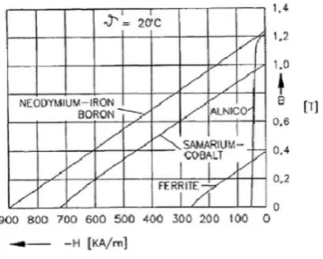
[image:1.595.350.531.265.410.2]had been developed. Now-a-day, widely used magnetic material is NdFeB which is more suitable for motor applications. NdFeB magnets have more corrosion susceptibility, but may be treated to limit such effects [4]. Fig. 1 shows demagnetization curve for various magnetic materials available for electric motors.
Fig. 1: Demagnetization curve of PM materials
The main disadvantage of PMSM is their inability to line-start from zero speed under load. PMSMs are, therefore, equipped with different position sensors and fed from current controlled voltage converters [5]. But, in LSPMSM, the squirrel-cage enables line-starting capability and damping of dynamic oscillations. The motors were “line-start”, a combination between an induction rotor machine and magnets, supplied from AC source. This type of motor is capable of line-starting under load; it exhibits higher power factor and efficiency values when compare to an induction motor with equal dimensions and rated data; also the position sensor is no longer needed [6]. The higher efficiency of the line-start PMSM also means that the machine is operating at lower temperature at equal load, providing opportunities for increasing the rated power. The motor manufacturers can penetrate markets with strict regulations regarding electromotor efficiency, by supplying high-efficient line-start PMSM instead of less-efficient induction motors, which are not intended for heavy starting, e.g. ventilator drives [7].
II. MODELLING LINE START PMSM The voltage equation for
stator is:
High Performance Line Started PMSM:
Modeling and Analysis
Here, stator winding phase resistance is Rs and p=d/dt and The equations for voltage of rotor are
Rotor coil having dc excitation current, Ifm is used to model
the PM, then
The equations for flux linkage equations are;
Here, d and q axis inductances have relation with stator and rotor leakage inductances as
,
,
Here the leakage inductance of stator and rotor are L1 and L2,
respectively.
The rotor acceleration at any instant is,
Where the number of poles = P, rotor angular speed= ωr, and
number of rotor inertia= J. Also, load torque= TL and
electromagnetic torque= Te.
The rotor cage torque is given as:
The braking torque produced due to the presence of permanent magnet is given by:
The resultant electromagnetic torque, Te is represented as:
During steady state operation, the torque in the form of currents is given by
In the form of voltage, if δ is the angle between Eo and Vph1,
neglecting resistance,
This resultant torque is known as synchronous torque.
III. DESIGN OF LSPMSM
[image:2.595.379.493.209.322.2]In recent years, advances in the design of personal computers have led to significant increases in computational and data storage ability. This has allowed the development of fast and powerful software packages for use in the design and analysis of electric machines. Analytical and finite element computer programs are now an essential part of the design process, and are used to create optimized designs ready for prototyping. As more sophisticated programs are developed, more computationally-intensive analysis methods are possible.
Fig. 2: Model of Line Start PMSM
For those motor topologies whose properties cannot easily be calculated by equivalent circuits or the classical phasor diagram, the use of software such as finite element analysis programs is essential.
While modeling and simulation are an essential part of the design process, the performance of the machine must be verified by measurement of its electrical and mechanical properties. The measured properties of the machine should be used to make adjustments to the prototype design and may be used as an input to further design calculations; they are also useful as a tool for calibration of the motor model.
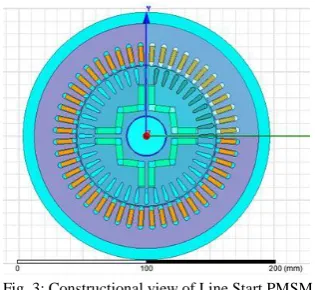
Fig. 3: Constructional view of Line Start PMSM
Although there is a wealth of literature concerning the measurement of magnetization characteristics of permanent-magnet motors, there are no internationally recognizable standards, such as those of the IEC or the ASTM, at present. This raises a number of key questions: What are the most suitable ways of defining the magnetization characteristics of each type
of motor?
[image:2.595.355.513.510.655.2]permanent-magnet motors as to other motor topologies? What is the best way to model the motors in analytical or finite element design programs?
How can the properties of the lamination materials, as measured from sheet steel samples, be used in calculations of motor characteristics?
The objective of the study is to examine the existing methods of measurement and investigation of magnetization features of PMSM and lamination materials used in the construction of such machines.
The two-dimensional and three-dimensional simulation software for electromagnetic analysis, Maxwell from Ansoft Corporation can carry GUI simulation in both frequency and time domain electromagnetic fields in complex 2D and 3D structures. In this paper, it is employed to simulate and evaluate the performance of the line-start PMSM. Widely used FEA based ANSYS Maxwell software is utilized for design and investigation of the motor.
IV. RESULTS
The motor performance can be analyzed by two stages of operation, i.e., transient stage and steady state stage. Transient Operation:
[image:3.595.311.561.69.206.2]The line started motor starts as conventional induction motor, by the action of two torques, cage torque and magnet braking torque.
Fig. 4: Rotational Speed of Line Start PMSM
[image:3.595.316.556.312.461.2]At the time of starting, peak values of current, torque and speed are the prominent parameters for the prediction of starting performance of Line Start PMSM. When the motor achieves near synchronous speed, the process of synchronization is started and motor state starts transition from transient state to the steady state.
Fig. 5- Torque developed by Line Start PMSM
[image:3.595.61.291.422.558.2]In steady state, the motor behaves like synchronous motor and runs at synchronous speed. The simulated speed-time characteristic shows that the motor is pulled into synchronism at around 0.50 s after the start.
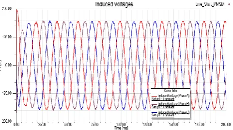
Fig. 6: Currents induced in winding
Rotor magnets when acted upon with the stator poles or teeth, cogging torque is generated which does not depends on the stator current at all.
[image:3.595.308.549.520.654.2]Fig. 8: Voltage and Current induced in the winding end connections
Steady State Operation:
[image:4.595.320.536.52.181.2]Steady state analysis plays a vital role for the prediction of the performance of motor. Steady-state performance of an LSPMSM is investigated in detail using FEM. In steady state, no current flows in the squirrel cage bars, so there is no rotor copper loss in the motor.
Fig. 9: Magnetic flux lines in LSPMSM
[image:4.595.74.266.318.436.2]In steady state the motor works as synchronous motor and runs at synchronous speed. Figure (9) shows the magnetic flux lines in LSPMSM.
Fig. 10: Magnetic field Intensity in LSPMSM
Figure-11 demonstrates the magnetic flux density distribution of the machine, based on which the flux paths and the corresponding magnetic equivalent circuit are extracted.
Fig. 11. Magnetic flux density in LSPMSM
[image:4.595.349.504.318.449.2]Here, 2D finite element model of LSPMSM is utilized for the verification of the obtained results. During the FE simulation of electrical machines, the meshing is essential process which is done to descretize the geometry developed into small number of parts called cells. The meshing may be initial meshing and adaptive meshing. A quarter geometry of the machine is subdivided into triangular elements. Fig. 12 shows the mesh plot of the motor.
Fig. 12: Finite Element Mesh in LSPMSM
CONCLUSION
Line started PMSM is new variety of motor which may be used in fans, pumps and compressor. FEM plays a vital role in designing and studying of LSPMSM. A very rigorous investigation has been done for magnet shapes and dimensions. By doing so, we have designed the various structures of stator and rotor laminations and windings. By using this technique, LSPMSM is successfully simulated under given conditions. Finite element based 2-D time stepping method is utilized to study the steady state as well as transient performance of the machine. The results came out after simulation confirms the good hold on the validity of the designed model. The magneto static analysis is performed to obtain various steady state performance parameters. The transient field is utilized to study the starting process of LSPMSM.
APPENDIX
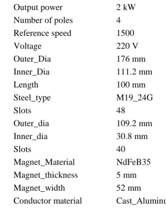
[image:4.595.48.275.517.652.2]Table. 1
Design data of the proposed LSPMSM Output power
Number of poles Reference speed Voltage 2 kW 4 1500 220 V Stator Outer_Dia
Inner_Dia Length Steel_type Slots 176 mm 111.2 mm 100 mm M19_24G 48 Rotor Outer_dia
Inner_dia Slots Magnet_Material Magnet_thickness Magnet_width Conductor material 109.2 mm 30.8 mm 40 NdFeB35 5 mm 52 mm Cast_Aluminum REFERENCES
1. J. F. Gieras and M. Wing, “Permanent Magnet Motor Technology , second edition, volume -1. M Wing, New York: Marcel Dekker Inc., 2002.
2. A.M. Knight and C.I. McClay “The design of High-Efficiency Line-Start Motors” , IEEE Trans. on Ind. Appl., Vol. 36, No. 6, pp. 1555-1562, Nov./ Dec., 2000.
3. V.B. Honsinger, “Performance of polyphase permanent magnet machines,” IEEE Transaction on Power Apparatus and Systems, Vol. PAS-99, No.4, pp.1510- 1518.
4. Rare-Earth Permanent Magnets. (2011) www.bakkermagnetics.com. 5. J. Pyrhönen, T. Jokinen and V. Hrabovcová, Design of Rotating
Electrical Machines, first edition, volume 1. West Sussex: John Wiley & Sons, 2008.
6. T.J.E. Miller, “Synchronization of line start permanent magnet AC motors,” IEEE Trans., vol. PAS-103, No.7, July 1984, pp. 1822-1828. 7. B. Adkins and R.G. Harley, “The general theory of alternating current
machines”, Chapman & Hall, London, 1978.
8. M. Popescu, T.J.E. Miller, M.I. McGilp, G. Strappazzon, N. Trivillin and R. Santarossa. “Line-Start Permanent-Magnet Motor: Single-Starting Performance Analysis”, IEEE Trans. on Industry Appl., 2003, Vol. 39, No.4, pp. 1021-1030.
9. K. Kurihara and M.A. Rahman. “High efficiency line-start interior permanent magnet synchronous motors”, IEEE Transactions on Industry Applications, Vol. 40, Issue: 3, pp. 789- 796, 2004. 10. K.J. Binns, W.R. Barnard and M. A. Jabbar. "Hybrid permanent
magnet synchronous motors", IEE Proceedings, part B, vol. 125, no.3, pp. 203-208, 1978.
11. T. Diao, X. Wang ,Y. Wang and Y. Pei, “Finite Element Analysis of Transient Behavior of Permanent Magnet Synchronous Motor”, 2011 Int. conference on machines and systems, 2011.
12. M.V.K. Chari and Z. J. Cscndcs. 1977. Finite Element Solution Of Saturable Magnetic Field Problem, IEEE trans. on Magnetics, Vol. MAG-l3, No.5 pp 1125-27. 1977.
13. Bell, J.F. 1993. Permanent magnet materials, IEE Colloquium on Permanent Magnet Machines and Drives, 1993, pp. 111-114. 14. Bo Yan, Xiuhe Wang, and Yubo Yang. “Starting Performance
Improvement of Line-Start Permanent-Magnet Synchronous Motor Using Composite Solid Rotor” IEEE Transactions On Magnetics, Vol. 54, No. 3, March 2018.
15. L. Maraaba, Z.A. Hamouz, A. Milhem, M. Abido. “Modelling of interior-mount LSPMSM under asymmetrical stator winding”, IET Electr. Power Appl., 2018, Vol. 12 Iss. 5, pp. 693-700.
16. M. Tian , X. Wang, D. Wang, "A Novel Line-Start Permanent Magnet Synchronous Motor With 6/8 Pole Changing Stator Winding", IEEE Transactions on Energy Conversion, Vol. 33, NO. 3, pp. 1164-1174, 2018.
17. A.J. Sorgdrager, R.J. Wang a6nd A.J. Grobler. “Multi-objective Design of a Line-Start PM Motor Using the Taguchi Method”, IEEE Trans. On Ind. Appli., Vol. 54, No. 5, 2018, pp. 4167-4176. 18. B.H. Lee, J.W. Jung, and J.P. Hong. “An Improved Analysis Method of
Irreversible Demagnetization for a Single-Phase Line-Start Permanent Magnet Motor”, IEEE Transactions On Magnetics, Vol. 54, No. 11, 2018.
19. K.J. Binns and M.A. Jabbar,(1981, May) “High-field self-starting permanent-magnet synchronous motor”, IEE Proc, Vol.128, Pt. B, No.3.
20. M.A. Rahman, A.M. Osheiba (1990, March) “Performance of Large Line-Start Permanent Magnet Synchronous Motors”, IEEE Transactions on Energy Conversion, Vol. 5, No.1, March 1990.
AUTHORSPROFILE
Arvind Kumar received B.Tech. degree from UPTU, Lucknow, U.P. and M.Tech. degree from GBPUA&T, Pantnagar. Presently, he is pursuing Ph.D in the Department of Electrical Engineering at GBPUA&T, Pantnagar, Uttarakhand.
Ajay Srivastava received B.E. degree from MMM Engineering College, Gorakhpur. He received his M.Tech. and Ph.D. degree from GBPUA&T, Pantnagar. Presently, he is working as Professor in Department of Electrical Engineering at GBPUA&T, Pantnagar, Uttarakhand.