DESIGN A BOW-TIE PATCH ANTENNA WITH COMPLEMENTARY SPLIT RING RESONATOR
SITI AISHAH BINTI ROSLI
This Report Is Submitted in Partial Fulfillment of Requirements for the Bachelor Degree of Electronic Engineering (Wireless Communication)
Faculty of Electronic and Computer Engineering Universiti Teknikal Malaysia Melaka
UNIVERSITI TEKNIKAL MALAYSIA MELAKA
FAKULTI KIJI.IRUTERAAN ELEKTRONIK DAN KEruRUTERAAN KOMPUTER
Tajuk Projek
Sesi Pengajian
BORANG PENGESAIIAII STATUS LAPORAN PROJEK SARJANA MUDA
II
DESIGN A BOW-TIE PATCH ANTENNA WITH
COMPLEMENTARY SPLIT RING RESONATOR
Saya SITI AISHAH BINTI ROSLI
mengaku membenarkan Laporan Projek Sarjana Muda ini disimpan di Perpustakaan dengan syarat-syarat kegunaan seperti berikut:
1.
Laporan adalah hakmilik Universiti Teknikal Malaysia Melaka.2.
Perpustakaan dibenarkan membuat salinan untuk tujuan pengajian sahaja.3.
Perpustakaan dibenarkan membuat salinan laporan ini sebagai bahan pertukaran ar:rJ"ata institusipengajian tinggi.
4.
Silatandakan({
),E
E
a
SUI,TT*
*(Mengandungi maklumat yang berdarjah keselamatan atau
kepentingan Malaysia seperti yang termaktub di dalam AKTA
RAHSTA RASMr 1972)
+*(Mengandungi maklumat terhad yang telah ditentukan oleh organisasi/badan di mana penyelidikan dijalankan)
TERHAD**
TIDAK TERHAD
e>
(TANDATANCAN PENULIS)
PIOI. TADYA M. SADRIT. HIs}OT BIT{ AHf,AO
TII{IAI.AN PENGARAH
Pusat Bimbinoan Kcriaya & Kcbolehpasaran Peiatat Jarinoin lrdusiri Dan Masyarakat (PJIM)
'
Univcrliti Tcknikal Malaysia irlelakaetlc,l
Ij
'" "t 1
I
2 1 3111
"I hereby declare that this report is the result of my own work except for quotes as
cited in the reference"
signature
, SY'
Author
: SITI AISHAH BINTI ROSLI1V
"I hereby declare that I have read this report and in my opinion this report is
sufficient in terms of the scope and quality for the award of Bachelor of Electronic Engineering (Wireless Communication) With Honours"
Supervisor's Name: ASSOC. PROF. DR. BADRUL HISHAM BIN
AHMAD
v
vi
ACKNOWLEDGEMENT
I am grateful to the Almighty with His grace and guidance that I was able to complete this thesis.
I take this opportunity to express my profound gratitude and deep regards to my guide (Assoc. Prof. Dr. Badrul Hisham Bin Ahmad) for her exemplary guidance, monitoring and constant encouragement throughout the course of this project. The blessing, help and guidance given by him from time to time shall carry me a long way in the journey of life on which I am about to embark.
I would like to thank everyone who involved directly and indirectly in this project. The sacrifice and commitment given towards me earning my bachelor’s degree are indescribable and without them, this thesis would not be completed.
vii
ABSTRACT
viii
ABSTRAK
ix
TABLE OF CONTENT
CHAPTER CONTENTS PAGE
PROJECT TITLE i
REPORT STATUS VERIFICATION ii
STUDENT’S DECLARATION iii
SUPERVISIOR DECLARATION iv
DEDICATION v
ACKNOWLEDGEMENT vi
ABSTRACT vii
ABSTRAK viii
CONTENT ix
LIST OF FIGURES xii
LIST OF TABLES xiv
LIST OF ABBREVAIATION xv
I INTRODUCTION 1
1.1 Introduction on a Rectenna 1
1.2 Objectives 3
1.3 Problems Statement 4
1.4 Project Scope 4
1.5 Methodology 5
II LITERATURE REVIEW 7
2.1 Overview of Antenna 7
x
2.3 Split Ring Resonator (SRR) 10
2.4 Complementary Split ring Resonator 12
2.5 Antenna Parameter 13
2.5.1 Gain 14
2.5.2 Input Impedance 15
2.5.3 In Voltage Standing Wave Ratio (VSWR) 16 2.5.4 2.5.5 2.5.6 2.5.7 2.5.8 Directivity Bandwidth Polarization
Radiation Pattern and 3dB Beamwidth Antenna Efficiency 17 17 18 20 20
III METHODOLOGY 22
3.1 Software 23
3.2 Materials 24
3.2.1 Photoresist Board 24
3.2.2 SMA Connector 24
3.2.3 SMA Adapter 25
3.3 Equipment 25
3.3.1 Network Analyzer 25
3.32 Signal Generator 25
3.33 RF Cable 26
3.34 Horn Antenna 26
3.4 3.5 3.6
Design Specifications Antenna Design
Antenna Design Simulation Process
27 28 31
3.6.1 Normal Bow-Tie Patch Antenna 31
3.6.2 Bow-Tie Patch Antenna with CSRR Design 34
3.6.3 Preparing The Layout 34
3.6.4 Etching Process 35
xi
IV RESULT AND DISCUSSION 39
4.1 Normal Bow-Tie Patch Antenna Design 39 4.1.1 Characteristic of Antenna(Return Loss) 40
4.1.2 Bandwidth 42
4.1.3 Surface Current 43
4.1.4 Directivity and Gain 44
4.1.5 Radiation Pattern 44
4.2
Bow-Tie Patch Antenna with Complementary Split Ring Resonator Design
4.2.1 Characteristic of Antenna(Return Loss) 4.2.2 Bandwidth
4.2.3 Surface Current 4.2.4 Directivity and Gain 4.2.5 Radiation Pattern
45
46 48 48 49 50
V CONCLUSION AND RECOMMENDATION 51
5.1 Conclusion 51
5.2 Recommendation 52
xii
LIST OF TABLES
Table Titles Pages
3.1 FR4 Board Parameter 24
3.2 Design specification 27
3.3 4.1 4.2
Characteristics of Antenna
Dimension of Normal Bow-Tie Patch Antenna Design Dimension of Bow-Tie Patch Antenna with CSRR Design
xiii
LIST OF FIGURES
Figure Titles pages
1.1 A simplified representation of a system for transmission and reception
2
1.2 Bow-tie antenna 3
1.3 Split ring resonator structure of the antenna design 3
1.4 Flow Chart for the Antenna Project 6
2.1 Structures of SRR tube 10
2.2 Pendry’s SRR and the equivalent circuit 11
2.3 Complementary split ring structure and equivalent circuit 13
2.4 Thevenin equivalent of an Antenna 15
2.5 Types of Polarization 19
2.6 Antenna reference terminals 21
3.1 3.2
CST microwave studio software Corel DRAW 12 software
23 23
3.3 Photoresist board 24
3.4 SMA connecter 24
3.5 SMA adapter 25
3.6 Network Analyzer 25
3.7 Signal Generator 25
3.8 RF Cable 26
3.9 Horn Antenna 27
3.10 Dimension of Bow-tie Patch Antenna 28
3.11 Substrate Design 32
xiv
3.13 Patch Design 32
3.14 Waveguide port design 33
3.15 Transient Solver Parameters 33
3.16 Normal Bow-Tie Patch Antenna 33
3.17 Bow-Tie Patch Antenna with CSRR Design 34
3.18 Antenna in UV Exposure Machine 35
3.19 Circuit Developer Chemical 35
3.20 Etching Machine 36
3.21 Drying Process 36
3.22 Calibration Setup and Antenna Measurement 37
3.23 Measurement Equipment 37
3.24 4.1 4.2
During Antenna Measurement Layout of Antenna
Structure of Antenna
38 39 39
4.3 Return Loss by Simulation, Measurement 41
4.4 Bandwidth 43
4.5 Surface Current 43
4.6 Gain of Antenna 44
4.7 4.8 4.9
Polar View Radiation Pattern of Antenna Layout of Antenna
Structure of Antenna
45 45 45
4.10 Return Loss by Simulation, Measurement 46
4.11 Bandwidth 48
4.12 Surface Current 49
4.13 Gain of Antenna 49
4.14 Polar View Radiation Pattern of Antenna 50
xv
LIST OF ABBREVIATIONS
WLAN WiMAX RFID FR4
-Wireless Local Area Network
-Worldwide Interoperability for Microwave Access - Radio Frequency Identification
-Flame Retardant 4
RF -Radio Frequency
PDA -Personal Digital Assistant
SMA PCB CST
-Sub Miniature Version A -Printed Circuit Board
-Computer Simulation Technology
UV -Ultra Violet
HPBW -Half Power Beamwidth
FNBW -First Null Beamwidth
CP -Circular Polarization
1
CHAPTER I
INTRODUCTION
This chapter will give an overview concerning the project as project background, project objective, project scope, project methodology and summary of the project. This chapter will additionally clarify briefly the overall project progress from beginning until the project is complete.
1.1 Introduction
Due to the development of wireless technology very fast, the broadband antenna technology has devised small antenna and power are necessarily used in many applications of communication such as Wireless Local Area Network (WLAN) for 2400MHz, Worldwide Interoperability for Microwave Access (WiMAX) for 2500 MHz to 2800MHz, Radio Frequency Identification (RFID) for 2450 MHz frequency range and others [1]. On the other hand, consumption requirement of small antenna which is very high for mobile phone users, PDA, laptop and notebook are incorporated with WI-Fi technologies to connect.
2
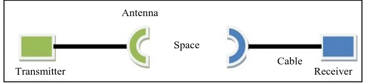
[image:17.595.132.524.194.279.2]the antenna to the receiver, it also often called radiant systems. A good antenna design is an antenna that can fulfill system requirements and improve overall system performance [2]. The original information is changed, for example through some kind of modulation and treatment, and still conveyed or guided by a cable to the antenna.
Figure 1.1: A simplified representation of a system for transmission and reception
In the future communication system, there will be a lot of demand to improve antenna performance due to increasing users, demand for higher speed in information transfer and the improvement in communication system technology. High bandwidth is one of the performance parameter because much wider bandwidth antenna will be needed when the frequency ranges is increasing than the originally required.
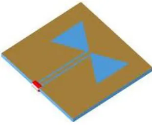
This project is focusing on designing a bow-tie patch antenna with complementary split ring resonator to increase gain and reduce the size of the antenna compare to the existing patch antenna without complementary split ring resonator structure [3]. A bow-tie antenna is based on a bi-triangular sheet of metal with the feed at its vertex as shows in Figure 1.2. This type of antenna is utilized extensively in many applications such as ground penetrating radar and mobile station. Bow-tie antennas have many advantages such as low profile, high radiation efficiency, ease of manufacturing and low fabrication cost [4]. Comparison between the bow-tie and fractal antenna shows that the bow-tie antenna has a wider bandwidth, higher gain, lower front-to-back ratio, lower cross-polarization level and smaller in size [5].
Antenna
Space
Cable
3
Figure 1.2: Bow-tie antenna
Split ring resonators (SRRs) structure is used to produce the negative permittivity or/and negative permeability as shows in Figure 1.3. This structure can be applied in many applications such as antenna, filter and microwave absorber. In 1999 by Pendry is the first man to develop a split ring resonator-base artificial negative magnetic permeability medium [1]. In the year of 2000, there was the first left hand medium (LHM) was developed with both negative permittivity and permeability by combining this structure with the array of strip wires (SW) [6].
Figure 1.3: Split ring resonator structure of the antenna design
1.2 Objectives
[image:18.595.191.446.410.512.2]4
1.3 Problems Statement
This project is undertaken as a solution for how to increase gain and miniaturize the size of the bow-tie patch antenna design. In applications where size, weight, cost, performance, ease of installation, and aerodynamic profile are constrained, low profile antennas like a bow-tie patch antenna with split ring resonator are required. Bow-tie patch antenna inherently has narrow bandwidth (BW) and in general is half-wavelength structures.
Meanwhile, bow-tie patch antenna with split ring resonator have several advantages over microstrip patch antenna such as exhibit wider bandwidth, lower dispersion and radiation loss, higher gain, lower front-to-back ratio, lower cross-polarization level and smaller in size.
1.4 Project Scope
The scope of this project involves the design, implementation and testing of bowtie patch antenna with split ring resonator. It can be divided into 5 main phases, which are designed the bowtie patch antenna with a new structure of complementary split ring resonator at 2.4 GHz for wireless LAN application. The bow-tie patch actually is the combination of imaginary image of two triangular patches which are fabricated on a single substrate. The design of bow-tie microstrip antenna is based on the design of triangular microstrip antenna with complementary split ring resonator. Since the dimension of bow-tie microstrip antenna, calculation and formula will be applied to measure the right dimension of the tie patch antenna design. A bow-tie patch antenna design with complementary split ring resonator will be designed, simulated, optimization in the CST Microwave Studio software.
5
1.5 Methodology
The first process in this project is the literature review. The review is to gather the information regarding bow-tie antenna via an IEEE journal, books, internet, journals, published work, reference books, magazine and study of the software implementation CST Microwave Studio.
The second process is a design of bowtie patch antenna with a new structure of complementary split ring resonator at 2.4 GHz for wireless LAN application. The designing and calculation processes are referring to the literature reviews that have been done in previous process. Then, the design was simulated with CST Microwave Studio to get the return loss, bandwidth, radiation pattern and the gain of the patch antenna. The normal bow-tie antenna is designed first then followed by a bow-tie patch antenna with complementary split ring resonator.
After that, the layout of the antennas is prepared before being fabricated. The simulated antenna was fabricated on FR4 board with dielectric constant, εr=4.3, tangential loss, tan δ=0.019 and thickness, h=1.6mm. The fabrication process consists of three steps which is UV exposure, developing, and etching. After fabrication, the SMA port will be connected and soldered to the antenna for measurement purpose.
6
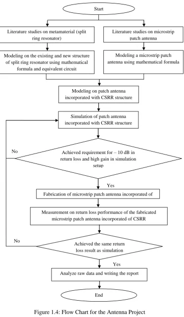
Figure 1.4:Flow Chart for the Antenna Project Measurement on return loss performance of the fabricated
microstrip patch antenna incorporated of CSRR
Achieved the same return loss result assimulation
Analyze raw data and writing the report
End
Yes Literature studies on metamaterial (split
ring resonator)
Modeling on the existing and new structure of split ring resonator using mathematical
formula and equivalent circuit
Literature studies on microstrip patch antenna
Modeling a microstrip patch antenna using mathematical formula
Modeling on patch antenna incorporated with CSRR structure
Simulation of patch antenna incorporated with CSRR structure
Achieved requirement for – 10 dB in return loss and high gain in simulation
setup
Fabrication of microstrip patch antenna incorporated of SRR
Yes No
No
7
CHAPTER II
LITERATURE REVIEW
This chapter will discuss about the fact and information about bow-tie antenna and development of the complementary split ring resonator.
2.1 Overview of Antenna
Around the 1830s, the early examination that encompassed the coupling of electricity and magnetism and displayed a definitive connection was that completed by Faraday. He skidded a magnetic concerning the coils of a wire attached to a galvanometer. In advancing the magnet, he was in result crafting a time-varying magnetic earth, that as a consequence (from Maxwell's Equations), have to have had a time-varying mechanical field. The coil replaced as a loop antenna and consented the electromagnetic radiation that was consented by the galvanometer - the work of an antenna. Interestingly, the believed of electromagnetic waves had not even been believed up at this point.
8
might be categorized as an antenna; though as it can't send waves, it is truly a sensor [7].
In the 1860s, when James Clerk Maxwell, fused electricity and magnetism into electromagnetism, he delineated light as and proved it to be an electromagnetic phenomenon. He forecasted the attendance of electromagnetic waves at wireless frequencies that is at far lower frequency than light. In 1886, Maxwell was proven right by Heinrich Rudolf Hertz who lacking comprehending it himself crafted the early ever wireless arrangement, encompassing of a transmitter and a receiver [8].
An antenna is the interface amid transmitter line and space. The frank believed to comprehend considering antennas is that they are passive devices. It’s because, to work, they need no supply voltage. As well that, they do neither change nor procedure RF gesture exceptionally to amplify the power of RF signals. In the supplementary word, an antenna merely converts an electromagnetic gesture to an mechanical gesture at a receiver or mechanical gesture to an electromagnetic gesture at a transmitter [9].
If they are 100 % effectual, they exude no extra manipulation than is held to their input terminal. This is because all the power of the gesture is definitely absorbing. An antenna can be described as a conductor utilized for exuding electromagnetic power into space or for accumulating electromagnetic power from space. In broadband wireless, there are countless kinds of antennas obtainable to suit the necessities of the application. The main aspect of antenna selection is normally gain, but equally vital criteria contain such things as beamwidth, side and rear lobe rejection, cross-polarity isolation, and VSWR (voltage erect wave ratio).
2.2 Bow-tie Antenna
9
of bi- triangular dipole antenna. These antennas have many advantages such as low fabrication cost, high radiation efficiency, ease of manufacturing & low profile [12].
Bow-tie microstrip antennas have come to be appealing candidates in the present day communication scenario due to their compact nature compared to rectangular patches. The ever rising demand for compact wireless communication equipment explicitly necessitates research on compact antenna options and which sparked interest of many researchers worldwide in the field of bow-tie patch antennas. Though in the literature, only very few attempts have been made towards the analysis of this kind antenna. The bow-tie patch antenna as a compact one and counselled an empirical formula for the resonant frequency of this new geodesy. This kind of antenna is utilized extensively in many applications such as ground penetrating radar, wireless communications and mobile station.
The bow-tie antenna has a narrow bandwidth because it is an example of a travelling wave structure; the analysis of a theoretical infinite antenna resembles that of a transmission line. For an infinite antenna, the characteristic impedance at the point of connection is a purpose of the cone angle only and is autonomous of the frequency. Useful antennas have finite length and a definite resonant frequency. Bow-tie antennas are often frequently utilized in electromagnetic interference (EMI) assessing whichever for immunity assessing or emissions testing [13]. The main advantages of bow-tie antennas are easy design and broadband impedance. Bow-tie antenna has been extensively learned in wireless system due to its advantages, such as broad impedance bandwidth, easy construction, light weight, easy to build and low cost. Moreover, effortlessly flexible to hybrid and monolithic microwave consolidated route fabrication method at RF and microwave frequencies. Meanwhile, alongside the quick progress of mobile communications, the enhance of second-generation mobile communications to third-second-generation mobile communications is becoming inevitable [14].