© 2016, IRJET | Impact Factor value: 4.45 | ISO 9001:2008 Certified Journal | Page 2696
Efficiency and Bandwidth Improvement Using Metamaterial of
Microstrip Patch Antenna
Aakash Mithari
1, Uday Patil
21Student
Department of Electronics Technology Engg., Shivaji University, Kolhapur, Maharashtra, India
2Assistant Professor
Department of Electronics Technology Engg., Shivaji University, Kolhapur, Maharashtra, India
---***---Abstract -
This paper discusses efficiency and bandwidthimprovement of microstrip patch antenna using metamaterial. A patch antenna is designed and simulated for 2.4GHz. Substrate is used for this purpose is FR4 glass epoxy with dielectric constant of 4.4, thickness of 1.6mm. The shape used for conventional patch antenna is rectangular with insert feed. For metamaterial antenna Circular Split Ring Resonators (CSRR) are used. Metamaterial CSRR is designed and simulated for 2.4GHz. After comparing both antennas bandwidth and efficiency improvement of metamaterial antenna is reported. High Frequency Structured Simulator (HFSS) EM simulator is used for this purpose.
Key Words: Microstrip Rectangular Patch antenna
(MRPA), Metamaterial, Circular Split Ring Resonators (CSRR)
1.INTRODUCTION
The microstrip patch antennas are commonly used in the wireless devices. Therefore, the miniaturization of the patch antenna becomes an important issue in reducing the volume of entire communication system. The common method for reducing the microstrip patch antenna size is to utilize a high permittivity dielectric substrate [1-2]. But, these antennas are -more expensive, have less radiation efficiency and narrow bandwidth. To overcome the above drawbacks, many design techniques for the patch antenna have already been proposed. These techniques are inserted slot, the meandering slots, the corrugation structure, iris structure and the shorting pin. However, all of these design strategies have limitations, such as complex structure and low performance. The design methods of the miniaturized patch antenna with metamaterial
technology have been reported by some authors. Victor Georgievich Veselagowas the first who theoretically presented that refractive index may also be negative. Up to this point, refractive index was traditionally regarded as having only positive values. Negative refraction can occur if both the (electric) permittivity and the magnetic permeability of a material are negative. This prediction was confirmed 33 years later when David Smith created a composite material with negative refractive index [3]. The material with negative permittivity and permeability is also known by several names such as left-handed material (LHM) and backward wave material (BWM). Although metamaterial is not present in nature, interesting properties were theoretically predicted for these substances, such as the reversal of the Snell’s Law, Doppler Effects and Cherenkov radiation and built perfect lenses [4].
By introducing the circular split ring (CSRR) structure microstrip gaps in the end behavior which is equivalent to combination of series capacitors and shunt inductors. Microstrip gap leads to negative permeability. Metamaterial antenna using six periodic CSRR gives the overall efficiency of 95.73% and return loss is -15.17 at 2.4GHz frequency [5]. In this paper, the miniaturized microstrip patch antenna with CSRRs is presented.
2. ANTENNA GEOMETRY
© 2016, IRJET | Impact Factor value: 4.45 | ISO 9001:2008 Certified Journal | Page 2697 dielectric material with relative permittivity (εr) of 4.4
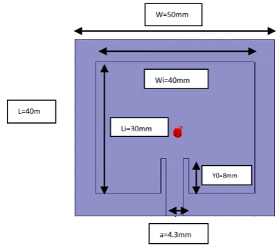
with thickness (h) of 1.6mm is chosen. The conventional MSA is designed for 2.4GHz with dimensions ‘Li’ and ‘Wi’ radiating patch, which is excited by simple 50 Ω microstrip feed having dimensions length ‘lp’ and width ‘a’ for their impedance matching
[image:2.595.42.244.198.376.2]
Fig -1: Conventional Patch antenna
The width of the patch antenna is calculated by formula (1)
Where
C – Velocity of light in air = 3 m/s. F – Frequency of antenna = 1.4 Hz.
- Dielectric constant of substrate = 4.4
W= 39.03 mm.
Effective dielectric constant as given by Hammersted and Jensen [6],
= (2)
If the height of the substrate = 1.6 mm, then from equation (2)
= 4.2.
Due to effect of fringing fields the length (L)
increases by from physical length, which is given by length extension ( )
(3)
As patch width is 39.03mm and = 4.2 then from eq. (3)
= 0.0024
Effective length of the patch
= (4)
= 30.49 mm.
Actual length of the patch:
(5)
L = 30 mm.
Ground plane calculations:
6h+W = 49.83 = 50mm (6) 6h+L = 39.04 = 40mm (7) The dimensions of conventional patch antenna obtained using the above equations are listed in Table 1.
Table -1: Parameters of Conventional Patch Antenna
Input parameters Values
Width of patch 40 mm
Effective dielectric constant 4.2
Length of patch 30 mm
Conductance of the patch (G1)
Insert feed point distance (y0) 13mm
Width of the strip line ( Wo) 4.3 mm
Substrate length and width (WxL) 50mmx40mm
L=40m m
Wi=40mm
Li=30mm
Y0=8mm
© 2016, IRJET | Impact Factor value: 4.45 | ISO 9001:2008 Certified Journal | Page 2698
3. METAMATERIAL GEOMETRY
[image:3.595.330.542.100.378.2]
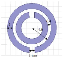
After obtaining the results for conventional patch, a metamaterial structure is incorporated into the antenna design on another layer of FR4 substrate of thickness 1.6mm. A small circular split ring resonator (SRR) loaded microstrip patch antenna with a CPW fed is designed. The circular split ring resonator is designed and tested in a waveguide.
Fig -2: Proposed CSRR Structure
Figure 3 shows the configuration of the proposed antenna.
For the observation of the proposed metamaterial structure of figure 2, Dominant mode waveguide having lowest cut-off frequency in TE10 mode have been designed. The cutoff frequency is the frequency below which the waveguide will not operate. Cut-off frequency for waveguide 1.8 GHz which calculated from the following formula. Proposed waveguide structure shown in figure 3(b).
The cutoff frequency is given by,
(8)
(a)
(b)
Fig -3: (a) Geometry for rectangular waveguide, (b) waveguide structure for cut-off Frequency of 1.8GHz
[image:3.595.97.223.272.389.2]As per calculations we got cut-off frequency for waveguide to 1.8276 GHz which shown in figure 4. In order to know for which frequency the metamaterial structure resonates. The proposed metamaterial structure is placed between two waveguide ports as shown in figure 5. Left and Right hand side of the y- axis and z-axis are defined as Perfect Electric (PEC). Two x-planes given as source port.
[image:3.595.318.550.545.695.2]© 2016, IRJET | Impact Factor value: 4.45 | ISO 9001:2008 Certified Journal | Page 2699 Fig -5: Proposed CSRR structure is placed between two
waveguide ports.
The S-parameters for the proposed metamaterial structures are observed. S-11 is -26 dB at 2.4GHz is reported as in figure 6. The designed metamaterial loaded patch antenna with its E- Field is reported in figure 7.
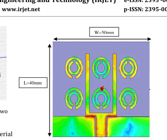
Fig -6: characteristics of metamaterial structure Proposed patch antenna has been designed by loading with metamaterial on U-shape. For providing metamaterial property (interdigital capacitance and inductance) in the proposed antenna CSRR’s are introduced to both arms of U-shape patch antenna. Split ring resonators don’t have any physical connection. So CSRR’s are excited by Electromagnetic coupling between ring and source patch. Figure 7 shows the current distribution on the patch near the resonance at 2.4 GHz. At the upper edges of U-shape maximum E-Field is observed. The charges at upper edges will jump to CSRR and these rings will get excited. The current is distributed mainly along edges and the feed point.
Fig -7: Metamaterial Loaded Patch Antenna and its E-Field
4. Results and Analysis
1. -characteristics:
1.00 1.50 2.00 2.50 3.00 3.50 4.00
Freq [GHz] -20.00
-17.50 -15.00 -12.50 -10.00 -7.50 -5.00 -2.50 0.00
d
B(S
(1
,
1
))
fr4
XY Plot 1 ANSOFT
m3 m1 m2
Curve Info
dB(S(1,1)) Setup1 : Sw eep Name X Y
m1 2.3398 -10.0036
m2 2.4583 -9.9926
m3 2.4000 -19.6092
(a)
1.00 1.50 2.00 2.50 3.00 3.50 4.00
Freq [GHz] -25.00
-22.50 -20.00 -17.50 -15.00 -12.50 -10.00 -7.50 -5.00 -2.50
d
B(S
(1
,1
))
patch antenna CSRR3
XY Plot 1 ANSOFT
m1
m3
m4
Curve Info dB(S(1,1)) Setup1 : Sw eep Name X Y
m1 1.6154 -10.1662 m3 2.1538 -15.1743 m4 2.7576 -9.9553
(b)
Fig -8: (a) Simulation of Return Loss - of conventional patch antenna. (b) S11 Simulation of Return Loss - of metamaterial loaded patch antenna.
L=40mm
[image:4.595.53.268.353.479.2]© 2016, IRJET | Impact Factor value: 4.45 | ISO 9001:2008 Certified Journal | Page 2700 In conventional patch RL = -19 dB at resonating
frequency of 2.4 GHz is reported as in figure 8(a) and the bandwidth achieved is only 16 MHz. In metamaterial loaded patch antenna RL = -15.17 dB at resonating frequency of 2.4 GHz is reported. The return loss of -10 dB is observed over the range of 1.6 GHz-2.7 GHz i.e. in the proposed metamaterial structure achieved bandwidth is up to 1GHz seen from figure 8(b).
2. Radiation Pattern:
Figure 9, is the simulated radiation pattern at frequency for 2.4 GHz. From figure 9(b), it is clear that the radiation pattern displays a directional behavior, with its main lobe direction at 0˚ and 180˚.
(a)
(b)
Fig -9: (a) Radiation Pattern Conventional Patch Antenna. (b) Radiation pattern of metamaterial loaded antenna
Figure 9(b), this indicates that the concentration of the field focuses on the sides of the patch. Meanwhile,
the lobes are suppressed at 90˚ and 270˚, which originate from the front part and back part of the patch antenna.
Radiation efficiency is also measured, for conventional patch we got efficiency of 56% only. While for metamaterial loaded patch efficiency is approximately 96%, around 40% efficiency increment is achieved.
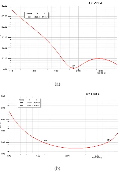
3. VSWR Characteristics:
(a)
(b)
Fig -10: (a) VSWR characteristic for conventional patch, (b) VSWR characteristic for metamaterial loaded patch.
[image:5.595.320.558.234.573.2] [image:5.595.66.277.323.701.2] [image:5.595.307.556.612.740.2]
© 2016, IRJET | Impact Factor value: 4.45 | ISO 9001:2008 Certified Journal | Page 2701
Table -2: Comparison Table between Conventional Patch antenna and Metamaterial Loaded Patch antenna
Parameter Simple Patch Metamaterial patch
Size (in mm) 50x40x1.6 50x40x1.6
Frequency 2.4 GHz 2.4GHz
Frequency range 2.32 GHz – 2.45 GHz
1.62 GHz - 2.7 GHz
Bandwidth achieved 11 MHz 1 GHz
Return Loss -19 dB -15.17 dB
Radiation Pattern One-directional Bi-directional
Efficiency 56.96 95.73
5. CONCLUSION
The effect of periodic structure of SRRs on a microstrip patch has been studied. The bandwidth and efficiency of the antenna showed an increase as compared to normal patch. Bandwidth achievement is 1GHz as compared to 16MHz for the conventional patch antenna. The efficiency of metamaterial CSRR is 95.73% as compared to 56.96 % of conventional patch. This is due to introduction of interdigital capacitance and inductance
REFERENCES
[1] Constantine A. Balanis, “Antenna theory, Analysis and Design”, Third edition, Wiley India, 2011. ISBN: 978-81-265-2422-8.
[2] Rodney B. Waterhouse, “Microstrip Patch Antennas: A Designers Guide”, Kluwer Academic Publishers, 2003. ISBN: 1-4020-7373-9.
[3] V.G. Vesalgo, “Electrodynamics of Substances with Simultaneously Negative Values of ε and μ", Soviet PHYSICS upekshi, volume. No-4, January-February 1968. [4] Huda A. Majid, Mohamad Kamal A. Rahim, and Thelaha Masri, “Left Handed Metamaterial Design For Microstrip Antenna Application”, IEEE International RF And
Microwave Conference Proceedings, December 2-4, 2008.
[5] Sunil Kumar Thakur, “Design and analysis of microstrip patch antenna metamaterial”, International Society of Thesis Publication, 2012
[6] Hammerstad, E., & Jensen, Ø. (1980). Accurate models for microstrip computer-aided design. In Symposium on
Microwave Theory and Techniques, pp. 407–409, June
1980.
[7] Jyotisankar Kalia, thesis “DESIGN OF METAMATERIAL BASED ANTENNA USING UNIT CELLS”, National Institute of Technology, Rourkela.
[8] H.Nornikman, B. H. Ahamad,“Effect of Single Complementary Resonating Structure on Microstrip Patch
Antenna Design”, IEEE symposium on Wireless Technology and Application, 2012.
[9] Monish Gupta, Jyoti Saxena “Micro-strip Filter Designing by SRR Material”, Wireless Peres Commun (2013). [10] Ricardo Marques, “Comparative analysis of Edge and
Broad Coupled Split Ring Resonators for meta-material Design”, IEEE Transactions on Antennas and Propagation, Vol. 51, No 10, October 2003.
BIOGRAPHIES
Mr. Aakash Mithari
M.Tech – Embedded Systems Department of Technology, Shivaji University, Kolhapur. Email: [email protected]
Mr. Uday A. Patil
Assistant Professor