Reconfigurable high Gain split Ring
Resonator Microstrip Patch Antenna
Japit S. Sonagara1, Karan H. Shah1, Jaydeep D. Suvariya1, Shobhit K. Patel2
PG Research Scholar, Dept. of E & C, Marwadi Education Foundation’s Group of Institutions, Rajkot, India1
Associate Professor, Dept. of E & C, Marwadi Education Foundation’s Group of Institutions, Rajkot, India2
ABSTRACT: In this paper, reconfigurable high gain split ring resonator microstrip patch antenna is designed and analysed. The aim to design such type antenna is to achieve multiband application which is the demand of current technology in frequency reconfiguration within single antenna. Here microstrip patch antenna with rectangle shape of patch with patch dimension 11.6×11.6 mm2 is analysed. The proposed design is tuned with two bands in the frequency range of 5-9 GHz depending on the geometric specification of antenna and the location of feed which can be used for multiband applications. Design results of VSWR, return loss (S11), bandwidth and gain are shown in this paper which is
obtained by high frequency structure simulator (HFSS) which is used for simulating microwave passive components.
KEYWORDS: Reconfigurable, Switching, Microstrip patch antenna, dual band, Split Ring Resonator, High gain.
I.INTRODUCTION
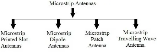
With rapid increasing technology in the field of recent wireless communication system, the designing of antenna with multiple frequencies and decreasing size is required [1]. It is necessary to design multiple frequencies antenna to complete the need of different application in current scenario [2]. This is done by microstrip patch antenna; it is attractive due to many advantages like small size, less weight, low cost, low profile, easy production and easy addition of feed network. Microstrip antennas provide more numbers of physical parameters as compared to conventional microwave antennas. Microstrip antenna also satisfies the need of WLAN. Microstrip patch antenna is sub divided into four basic categories as shown in figure1.
Fig. 1. Types of Microstrip Antenna
ISSN (Print) : 2320 – 3765 ISSN (Online): 2278 – 8875
I
nternational
J
ournal of
A
dvanced
R
esearch in
E
lectrical,
E
lectronics and
I
nstrumentation
E
ngineering
(A High Impact Factor & UGC Approved Journal)
Website: www.ijareeie.com Vol. 6, Issue 9, September 2017
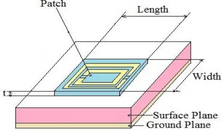
introducing slots in microstrip patch antenna it provides following advantage like, bandwidth of microstrip patch antenna is increased, efficiency is increased, improved VSWR, reduced size and increased gain [12-13]. It also gives output at multiple beam so it is helpful for multiple frequency application e.g. reconfigurable antenna. There are various types of slots available like C slot patch, H slot patch, S slot patch, L slot patch, U slot patch, V slot patch E slot patch etc. [14]. In our case we used C slot patch with complementary split ring resonator microstrip patch antenna. Design of complementary split ring resonator microstrip patch antenna is shown in a figure2.
Fig. 2. Structure of Microstrip Patch Antenna.
II. DESIGN AND MODELLING
This section gives the introduction of our antenna design. Here the first step is to design the length and width of patch.
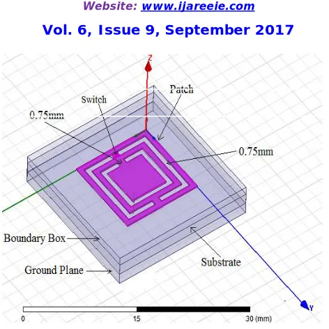
In our design split ring resonator is taken on the patch. Top view and side view of proposed split ring resonator is shown in a fig. 3 and fig. 4 respectively. The width of the patch is designed using below equation. Here fr is the center
frequency, r is the relative permittivity and c is speed of light. Using below equations the length of patch can be calculated. Here h is the height of substrate.
Following equations are used to design the length and width of the patch
(1)
(2)
(3)
Fig. 3. Top view of proposed Antenna.
Fig.4 Side view of proposed Antenna.
Thus a convenient patch is designed using above mentioned equations. In this paper we have taken square patch i.e. the length and width will be same and is taken as 11.60mm. Thus a square patch is of dimension 11.60×11.60mm2 which is shown in the above figure 3: . Here a Split Ring Resonator (SSR) is taken in the patch to increase the gain. The taken out SSR along with its dimension is shown in the figure 3. . Respectively the top view and side view of the design is also shown in the above figures. Table 1 describes the material of the patch which is copper with permittivity ɛr = 1 and
that of the substrate is of FR4 epoxy with permittivity ɛr = 4.4.
III. SIMULATION RESULTS AND DISCUSSION
ISSN (Print) : 2320 – 3765 ISSN (Online): 2278 – 8875
I
nternational
J
ournal of
A
dvanced
R
esearch in
E
lectrical,
E
lectronics and
I
nstrumentation
E
ngineering
(A High Impact Factor & UGC Approved Journal)
Website: www.ijareeie.com Vol. 6, Issue 9, September 2017
Table-1 value of Patch and Substrate for Proposed Antenna.
Material
Patch Copper with ɛr = 1
Substrate FR4 epoxy with ɛr = 4.4
Table-2 Design Parameters of Proposed Antenna design.
Parameter Values (mm)
Width of patch (w) 11.60
Length of patch (L) 11.60
Height of patch (t) 0.2
Width of substrate (ws) 20.6 Length of substrate (Ls) 20.6 Height of substrate (Hs) 1.55 Dielectric constant (ɛr) 4.4 Effective dielectric constant (ɛrff) 3.75
Height of ground (Hg) 0.5
Height of patch (hp) 0.2
Extended patch length (ΔL) 0.692
Inner radius of co-axial feed 0.12 Outer radius of co-axial feed 0.42
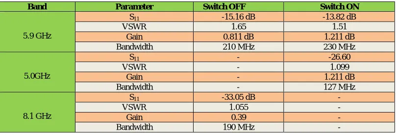
In table-2 show the precise dimension of various parameter of proposed design of antenna. Table 3 gives the complete description of the various parameters of the proposed antenna design such as S11, VSWR, gain and bandwidth for
different obtained bands.
Table-3 Simulation Results of Proposed Antenna design.
Band Parameter Switch OFF Switch ON
5.9 GHz
S11 -15.16 dB -13.82 dB
VSWR 1.65 1.51
Gain 0.811 dB 1.211 dB
Bandwidth 210 MHz 230 MHz
5.0GHz
S11 - -26.60
VSWR - 1.099
Gain - 1.211 dB
Bandwidth - 127 MHz
8.1 GHz
S11 -33.05 dB -
VSWR 1.055 -
Gain 0.39 -
Bandwidth 190 MHz -
Fig.5 Total Gain when switch is ON.
Fig.6 Total Gain when switch is OFF.
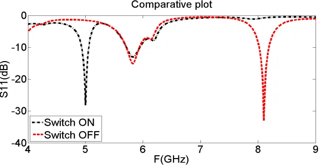
Figure 7 & 8 is the comparison plot of S11 parameter and VSWR respectively for switch OFF and switch ON and the
ISSN (Print) : 2320 – 3765 ISSN (Online): 2278 – 8875
I
nternational
J
ournal of
A
dvanced
R
esearch in
E
lectrical,
E
lectronics and
I
nstrumentation
E
ngineering
(A High Impact Factor & UGC Approved Journal)
Website: www.ijareeie.com Vol. 6, Issue 9, September 2017
Fig.8 Comparison of VSWR when switch is OFF and switch is ON.
Table-4 Resultant output for two different bands when switch is OFF.
Resultant Output when switch is OFF
Parameter 1st 2nd
Frequency in GHz 8.1 5.9
Minimum return loss (S11) in dB -33.05 -15.60
VSWR 1.055 1.65
Table-5 Resultant output for two different bands when switch is ON.
IV. CONCLUSION
Antennas have become a rapidly growing area of research in the recent wireless communication system .The reason behind is that the compact size, less weight, low cost, low profile, easy production and easy addition of feed Network. Here Split ring resonator type microstrip patch is designed for multiband applications. Here the simulation is carried out at centre frequency 6GHz.Output result contains two bands out of which one band is at 5.9GHz and other one is at 8.1MHz so the antenna can used for C Band and X Band Applications. Further design can be modified to have a multiband for other applications in Ku Band, K Band, Ka Band. The results obtained for reconfigurable microstrip patch antenna are more efficient as compared to other antennas so far designed for similar applications. In above design we have used FR4 as a substrate. Instead of FR4 as substrate, the artificial material, meta material along with multilayer substrate (super substrate) can be used further to improve results.
Resultant Output when switch is ON
Parameter 1st 2nd
Frequency in GHz 5.0 5.9
Minimum return loss (S11) in dB -26.60 -13.82
REFERENCES
[1] Patel, J. M., Patel, S. K., Thakkar, F. N. (2013). Defected ground structure multiband microstrip patch antenna Using complementary split ring resonator. International Journal of Emerging Trends in Electrical and Electronics, 3(2), 14-19.
[2] Sharma, K., Singh, S., Pani, S., Kumar, D., Tripathy, M. R. (2016,May). Multi-band antenna with enhanced gain for wireless applications. In Recent Trends in Electronics, Information Communication Technology (RTEICT), IEEE International Conference on (pp. 1671-1675). IEEE. [3] Singh, I., Tripathi, V. S. (2011). Micro strip patch antenna and its applications: a survey. Int. J. Comp. Tech. Appl, 2(5), 1595- 1599.
[4] Sung, Y. J., Jang, T. U., & Kim, Y. S. (2004). A reconfigurable microstrip antenna for switchable polarization. IEEE Microwave and Wireless Components Letters, 14(11), 534-536.
[5] Patel, S. K., & Kosta, Y. (2013). Triband Microstrip–Based Radiating Structure Design using Split Ring Resonator and Complementary Split Ring Resonator. Microwave and Optical Technology Letters, 55(9), 2219-2222.
[6] Jegan, G. (2010, November). Multi band microstrip patch antenna for satellite communication. In Recent Advances in Space Technology Services and Climate Change (RSTSCC), 2010 (pp.153-156). IEEE.
[7] Yadav, R., Yadav, S. K., Sharma, I. B. (2015, October). Reconfigurable single and dual band microstrip patch antenna for satellite communications. In Green Computing and Internet of Things (ICGCIoT), 2015 International Conference on (pp. 1565-1570). IEEE.
[8] Outerelo, D. A.,Alejos, A. V.,Sanchez, M. G.,Isasa, M. V.(2015,July). Microstrip antenna for 5G broadband communications: Overview of design issues. In Antennas and Propagation USNC/URSI National Radio Science Meeting, 2015 IEEE International Symposium on (pp. 2443-2444). IEEE.
[9] Majid, H. A.,Abd Rahim, M. K.,Hamid, M. R.,Ismail, M. F. (2014). Frequency reconfigurable microstrip patch-slot antenna with directional radiation pattern. Progress In Electromagnetics Research, 144, 319-328.
[10] Patel, S. K., & Kosta, Y. P. (2013). Design of truncated microstrip based radiating structure loaded by split ring resonator. International Journal of Applied Electromagnetics and Mechanics, 42(2), 249-258.
[11] . Patel, S. K., & Kosta, Y. P. (2012). Dualband parasitic metamaterial square microstrip patch antenna design. International Journal of Ultra Wideband Communications and Systems, 2(4), 225-232.
[12] Patel, S. K., & Argyropoulos, C. (2016). Enhanced bandwidth and gain of compact microstrip antennas loaded with multiple corrugated split ring resonators. Journal of ElEctromagnEtic WavEs and applications, 30(7), 945-961
[13] Patel, S. K., & Kosta, Y. P. (2014). Metamaterial superstrate-loaded meandered microstrip-based radiating structure for bandwidth
enhancement. Journal of Modern Optics, 61(11), 923-930.